parking TOYOTA RAV4 2006 Service Service Manual
[x] Cancel search | Manufacturer: TOYOTA, Model Year: 2006, Model line: RAV4, Model: TOYOTA RAV4 2006Pages: 2000, PDF Size: 45.84 MB
Page 1174 of 2000

AX–196U151F AUTOMATIC TRANSAXLE – AUTOMATIC TRANSAXLE UNIT
AX
24. REMOVE MANUAL VALVE LEVER SUB-ASSEMBLY
(a) Using a chisel and hammer, cut off and remove the
spacer.
(b) Using a pin punch (
35 mm) and hammer, drive out
the pin.
HINT:
Slowly drive out the pin so that it does not fall into
the transaxle case.
(c) Remove the manual valve lever shaft and manual
valve lever.
25. REMOVE PARKING LOCK ROD SUB-ASSEMBLY
(a) Remove the parking lock rod from the manual valve
lever.
26. REMOVE MANUAL VALVE LEVER SHAFT OIL SEAL
(a) Using a screwdriver, pry out the oil seal from the
transaxle case.
NOTICE:
Do not apply excessive force when removing
the oil seal.
27. FIX AUTOMATIC TRANSAXLE ASSEMBLY
(a) Fix the transaxle case in place with the oil pump
side facing up.
28. INSPECT INPUT SHAFT ENDPLAY (See page AX-213)
D003563E01
D003564E01
D003565E02
D026382E02
D003566E02
Page 1177 of 2000

U151F AUTOMATIC TRANSAXLE – AUTOMATIC TRANSAXLE UNITAX–199
AX
(b) Remove the parking lock pawl shaft.
(c) Push the parking lock pawl.
HINT:
Failure to do so will cause interference when the
underdrive planetary gear is removed.
(d) Remove the underdrive planetary gear from the
transaxle case.
NOTICE:
Make sure that the underdrive planetary gear
does not fall out.
39. REMOVE PARKING LOCK PAWL
(a) Remove the spring, pawl pin and parking lock pawl.
40. REMOVE UNDERDRIVE CLUTCH ASSEMBLY
(a) Remove the underdrive clutch, thrust bearing and
bearing race from the transaxle case.
D009652E01
D009689E01
D003579E04
D026386E01
D003580E02
Page 1208 of 2000
AX–230U151F AUTOMATIC TRANSAXLE – AUTOMATIC TRANSAXLE UNIT
AX
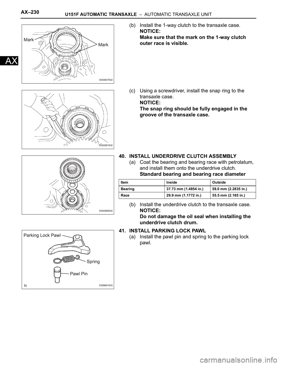
(b) Install the 1-way clutch to the transaxle case.
NOTICE:
Make sure that the mark on the 1-way clutch
outer race is visible.
(c) Using a screwdriver, install the snap ring to the
transaxle case.
NOTICE:
The snap ring should be fully engaged in the
groove of the transaxle case.
40. INSTALL UNDERDRIVE CLUTCH ASSEMBLY
(a) Coat the bearing and bearing race with petrolatum,
and install them onto the underdrive clutch.
Standard bearing and bearing race diameter
(b) Install the underdrive clutch to the transaxle case.
NOTICE:
Do not damage the oil seal when installing the
underdrive clutch drum.
41. INSTALL PARKING LOCK PAWL
(a) Install the pawl pin and spring to the parking lock
pawl.
D003627E02
D003581E02
D003580E02
Item Inside Outside
Bearing 37.73 mm (1.4854 in.) 58.0 mm (2.2835 in.)
Race 29.9 mm (1.1772 in.) 55.5 mm (2.185 in.)
D009691E03
Page 1209 of 2000
U151F AUTOMATIC TRANSAXLE – AUTOMATIC TRANSAXLE UNITAX–231
AX
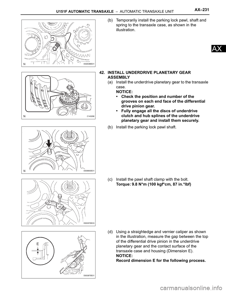
(b) Temporarily install the parking lock pawl, shaft and
spring to the transaxle case, as shown in the
illustration.
42. INSTALL UNDERDRIVE PLANETARY GEAR
ASSEMBLY
(a) Install the underdrive planetary gear to the transaxle
case.
NOTICE:
• Check the position and number of the
grooves on each end face of the differential
drive pinion gear.
• Fully engage all the discs of underdrive
clutch and hub splines of the underdrive
planetary gear and install them securely.
(b) Install the parking lock pawl shaft.
(c) Install the pawl shaft clamp with the bolt.
Torque: 9.8 N*m (100 kgf*cm, 87 in.*lbf)
(d) Using a straightedge and vernier caliper as shown
in the illustration, measure the gap between the top
of the differential drive pinion in the underdrive
planetary gear and the contact surface of the
transaxle case and housing (Dimension E).
NOTICE:
Record dimension E for the following process.
D026386E01
C140286
D009693E01
D003576E03
D003875E01
Page 1214 of 2000

AX–236U151F AUTOMATIC TRANSAXLE – AUTOMATIC TRANSAXLE UNIT
AX
53. INSTALL MANUAL VALVE LEVER SHAFT OIL SEAL
(a) Coat a new oil seal with MP grease.
(b) Install the oil seal to the transaxle case.
SST 09950-60010 (09951-00230), 09950-70010
(09951-07100)
Standard depth:
0 +- 0.5 mm (0 +- 0.197 in. )
54. INSTALL PARKING LOCK ROD SUB-ASSEMBLY
(a) Install the parking lock rod to the manual valve lever.
55. INSTALL MANUAL VALVE LEVER SUB-ASSEMBLY
(a) Install a new spacer and manual valve lever shaft to
the transaxle case.
NOTICE:
Do not damage the oil seal when installing the
shaft to the transaxle case.
(b) Using a pin punch and hammer, drive in a new pin.
(c) Turn the spacer and the lever shaft to align the small
hole (for locating the staking position in the spacer)
with the staking position mark on the lever shaft.
(d) Using a pin punch, stake the spacer through the
small hole.
(e) Check that the spacer does not turn.
D026468E01
D026382E02
D003565E01
D003564E01
D026765E03
Page 1215 of 2000

U151F AUTOMATIC TRANSAXLE – AUTOMATIC TRANSAXLE UNITAX–237
AX
56. INSTALL MANUAL VALVE LEVER SHAFT RETAINER
SPRING
(a) Using needle-nose pliers, install the retainer spring.
NOTICE:
Hang the spring on the shaft firmly.
57. INSTALL PARKING LOCK PAWL BRACKET
(a) Install the parking lock pawl bracket with the 2 bolts.
Torque: 20 N*m (205 kgf*cm, 15 ft.*lbf)
HINT:
The bolt length is indicated below.
Bolt length:
25 mm (0.984 in.)
NOTICE:
Make sure that the parking rod is placed
between the parking pawl and the guide of the
parking bracket when the parking bracket is
installed.
58. INSTALL MANUAL DETENT SPRING SUB-
ASSEMBLY
(a) Install the manual detent spring and cover with the 2
bolts.
NOTICE:
Make sure to install the manual detent spring
and cover in this order.
HINT:
Tighten bolt A first, and then bolt B.
Torque: 20 N*m (204 kgf*cm, 15 ft.*lbf) for bolt A
12 N*m (122 kgf*cm, 9 ft.*lbf) for bolt B
HINT:
Each bolt length is indicated below.
Bolt length:
27 mm (1.06 in.) for bolt A
16 mm (0.63 in.) for bolt B
59. INSTALL B-3 ACCUMULATOR PISTON
(a) Coat a new O-ring with ATF, and install it to the B-3
accumulator piston.
NOTICE:
Make sure that the O-ring is not twisted and that
it does not protrude abnormally from the
accumulator piston. Apply sufficient ATF before
installing the O-ring. The O-ring must be
installed in the correct position.
D003559E01
D003561E01
D003560E01
D003904E05
Page 1241 of 2000
U241E AUTOMATIC TRANSAXLE – AUTOMATIC TRANSAXLE SYSTEMAX–17
AX
(2) Check engine braking.
While driving the vehicle with the shift lever on L,
release the accelerator pedal and check the
engine braking effect.
(3) Check for abnormal noises during acceleration
and deceleration.
(e) R position test
Move the shift lever to R and lightly depress the
accelerator pedal. Check that the vehicle moves
backward without any abnormal noise or vibration.
CAUTION:
Before conducting this test, ensure that no
people or obstacles are in the test area.
(f) P position test
Stop the vehicle on an incline (more than 5
). Then
move the shift lever to P and release the parking
brake. Check that the parking lock pawl holds the
vehicle in place.
Page 1242 of 2000
AX–18U241E AUTOMATIC TRANSAXLE – AUTOMATIC TRANSAXLE SYSTEM
AX
MECHANICAL SYSTEM TESTS
1. STALL SPEED TEST
HINT:
This test is to check the overall performance of the
engine and transaxle.
NOTICE:
• Do not perform the stall speed test longer than 5
seconds.
• To ensure safety, perform this test in an open and
level area that provides good traction.
• The stall speed test should always be performed
with at least 2 people. One person should observe
the condition of the wheels and wheel chocks
while the other is performing the test.
(a) Connect the intelligent tester to the CAN VIM. Then
connect the CAN VIM to the DLC3.
(b) Run the vehicle until the transmission fluid
temperature has reached 50 to 80
C (122 to 176F).
(c) Allow the engine to idle with the air conditioning
OFF.
(d) Chock all 4 wheels.
(e) Set the parking brake and keep the brake pedal
depressed firmly with your left foot.
(f) Move the shift lever to the D position.
(g) Depress the accelerator pedal as much as possible
with your right foot.
(h) Read the engine rpm (stall speed) and release the
accelerator pedal immediately.
Standard value:
2,150 to 2,450 rpm
Evaluation:
NOTICE:
Perform the test at the normal operating ATF
temperature of 50 to 80
C (122 to 176F).
2. SHIFT TIME LAG TEST
HINT:
This test is to check the condition of the direct clutch,
forward clutch, 1st brake and reverse brake.
(a) Connect the intelligent tester to the CAN VIM. Then
connect the CAN VIM to the DLC3.
(b) Run the vehicle until the transmission fluid
temperature has reached 50 to 80
C (122 to 176F).
(c) Allow the engine to idle with the air conditioning
OFF.
Test Result Possible Cause
Stall speed is lower than standard value • Stator one-way clutch is not operating properly
• Torque converter is faulty (stall speed is less than standard value
by 600 rpm or more)
• Engine power may be insufficient
Stall speed is higher than standard value • Line pressure is low
• C1 clutch slipping
• F3 one-way clutch is not operating properly
• F4 one-way clutch is not operating properly
Page 1243 of 2000
U241E AUTOMATIC TRANSAXLE – AUTOMATIC TRANSAXLE SYSTEMAX–19
AX
(d) Set the parking brake and keep the brake pedal
depressed firmly.
(e) Check the D range time lag.
(1) Move the shift lever to N and wait for 1 minute.
(2) Move the shift lever to D and measure the time
until the shock is felt.
(3) Repeat the 2 procedures above 3 times, and
calculate the average time of the 3 tests.
(f) Check the R range time lag.
(1) Move the shift lever to N and wait for 1 minute.
(2) Move the shift lever to R and measure the time
until the shock is felt.
(3) Repeat the 2 procedures above 3 times, and
calculate the average time of the 3 tests.
Standard value:
D range time lag is less than 1.2 seconds
R range time lag is less than 1.5 seconds
Evaluation:
HYDRAULIC TEST
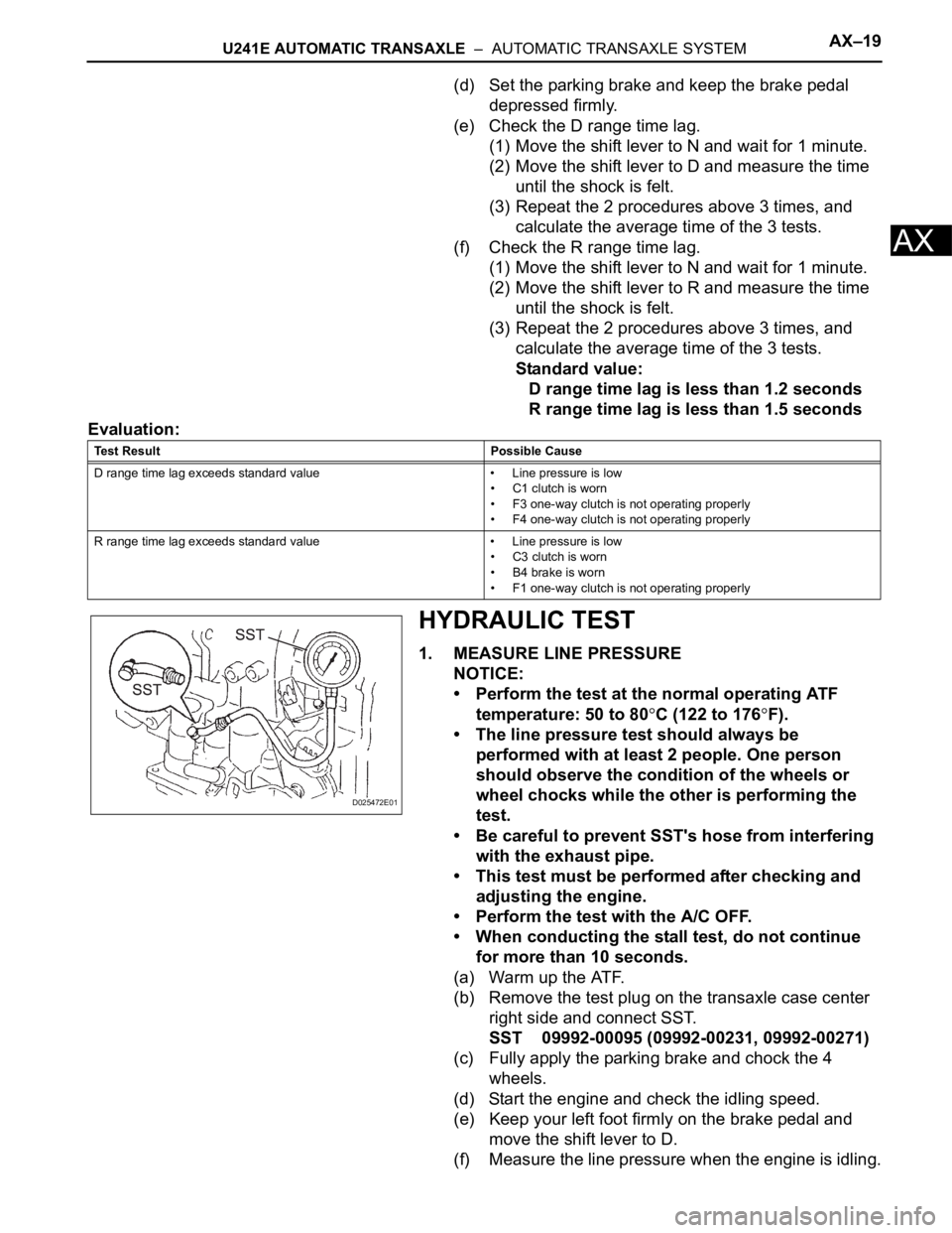
1. MEASURE LINE PRESSURE
NOTICE:
• Perform the test at the normal operating ATF
temperature: 50 to 80
C (122 to 176F).
• The line pressure test should always be
performed with at least 2 people. One person
should observe the condition of the wheels or
wheel chocks while the other is performing the
test.
• Be careful to prevent SST's hose from interfering
with the exhaust pipe.
• This test must be performed after checking and
adjusting the engine.
• Perform the test with the A/C OFF.
• When conducting the stall test, do not continue
for more than 10 seconds.
(a) Warm up the ATF.
(b) Remove the test plug on the transaxle case center
right side and connect SST.
SST 09992-00095 (09992-00231, 09992-00271)
(c) Fully apply the parking brake and chock the 4
wheels.
(d) Start the engine and check the idling speed.
(e) Keep your left foot firmly on the brake pedal and
move the shift lever to D.
(f) Measure the line pressure when the engine is idling.
Test Result Possible Cause
D range time lag exceeds standard value • Line pressure is low
• C1 clutch is worn
• F3 one-way clutch is not operating properly
• F4 one-way clutch is not operating properly
R range time lag exceeds standard value • Line pressure is low
• C3 clutch is worn
• B4 brake is worn
• F1 one-way clutch is not operating properly
D025472E01
Page 1274 of 2000

AX–170U241E AUTOMATIC TRANSAXLE – AUTOMATIC TRANSAXLE UNIT
AX
20. REMOVE B-3 ACCUMULATOR PISTON
(a) Apply compressed air (392 kPa, 4.0 kgf/cm
2, 57 psi)
to the oil hole and remove the B-3 accumulator
piston and 2 compression springs.
NOTICE:
• Applying compressed air may cause the
piston to jump out. When removing the
piston, hold it with your hand using a waste
cloth.
• Make sure not to spatter ATF when applying
compressed air.
(b) Remove the O-ring from the B-3 accumulator
piston.
21. REMOVE MANUAL DETENT SPRING SUB-
ASSEMBLY
(a) Remove the 2 bolts, manual detent spring and
cover.
22. REMOVE PARKING LOCK PAWL BRACKET
(a) Remove the 2 bolts and parking lock pawl bracket.
23. REMOVE MANUAL VALVE LEVER SHAFT RETAINER
SPRING
(a) Using needle-nose pliers, remove the retainer
spring.
D003558E02
D003904E05
D003560E03
C056727E01
D003559E01