Washer TOYOTA RAV4 2006 Service Manual Online
[x] Cancel search | Manufacturer: TOYOTA, Model Year: 2006, Model line: RAV4, Model: TOYOTA RAV4 2006Pages: 2000, PDF Size: 45.84 MB
Page 1896 of 2000
WIPER AND WASHER – WIPER SWITCHWW–27
WW
REMOVAL
1. DISCONNECT CABLE FROM NEGATIVE BATTERY
TERMINAL
CAUTION:
Wait at least 90 seconds after disconnecting the
cable from the negative (-) battery terminal to
prevent airbag and seat belt pretensioner activation.
2. PLACE FRONT WHEELS FACING STRAIGHT AHEAD
3. REMOVE STEERING PAD ASSEMBLY (See page RS-
336)
4. REMOVE STEERING WHEEL ASSEMBLY (See page
SR-12)
5. REMOVE STEERING COLUMN COVER UPPER (See
page SR-12)
6. REMOVE STEERING COLUMN COVER LOWER (See
page SR-12)
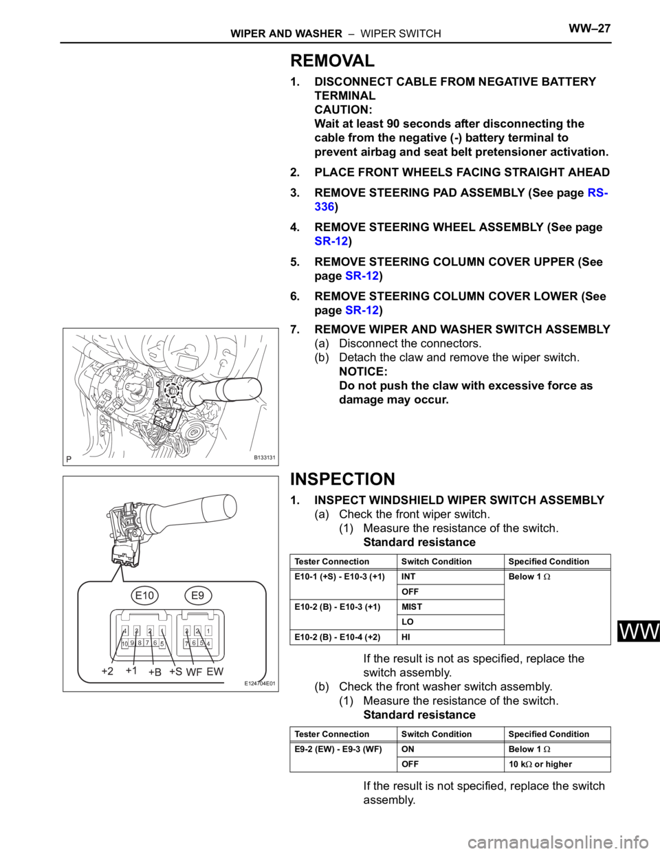
7. REMOVE WIPER AND WASHER SWITCH ASSEMBLY
(a) Disconnect the connectors.
(b) Detach the claw and remove the wiper switch.
NOTICE:
Do not push the claw with excessive force as
damage may occur.
INSPECTION
1. INSPECT WINDSHIELD WIPER SWITCH ASSEMBLY
(a) Check the front wiper switch.
(1) Measure the resistance of the switch.
Standard resistance
If the result is not as specified, replace the
switch assembly.
(b) Check the front washer switch assembly.
(1) Measure the resistance of the switch.
Standard resistance
If the result is not specified, replace the switch
assembly.
B133131
E124704E01
Tester Connection Switch Condition Specified Condition
E10-1 (+S) - E10-3 (+1) INT Below 1
OFF
E10-2 (B) - E10-3 (+1) MIST
LO
E10-2 (B) - E10-4 (+2) HI
Tester Connection Switch Condition Specified Condition
E9-2 (EW) - E9-3 (WF) ON Below 1
OFF 10 k or higher
Page 1897 of 2000
WW–28WIPER AND WASHER – WIPER SWITCH
WW
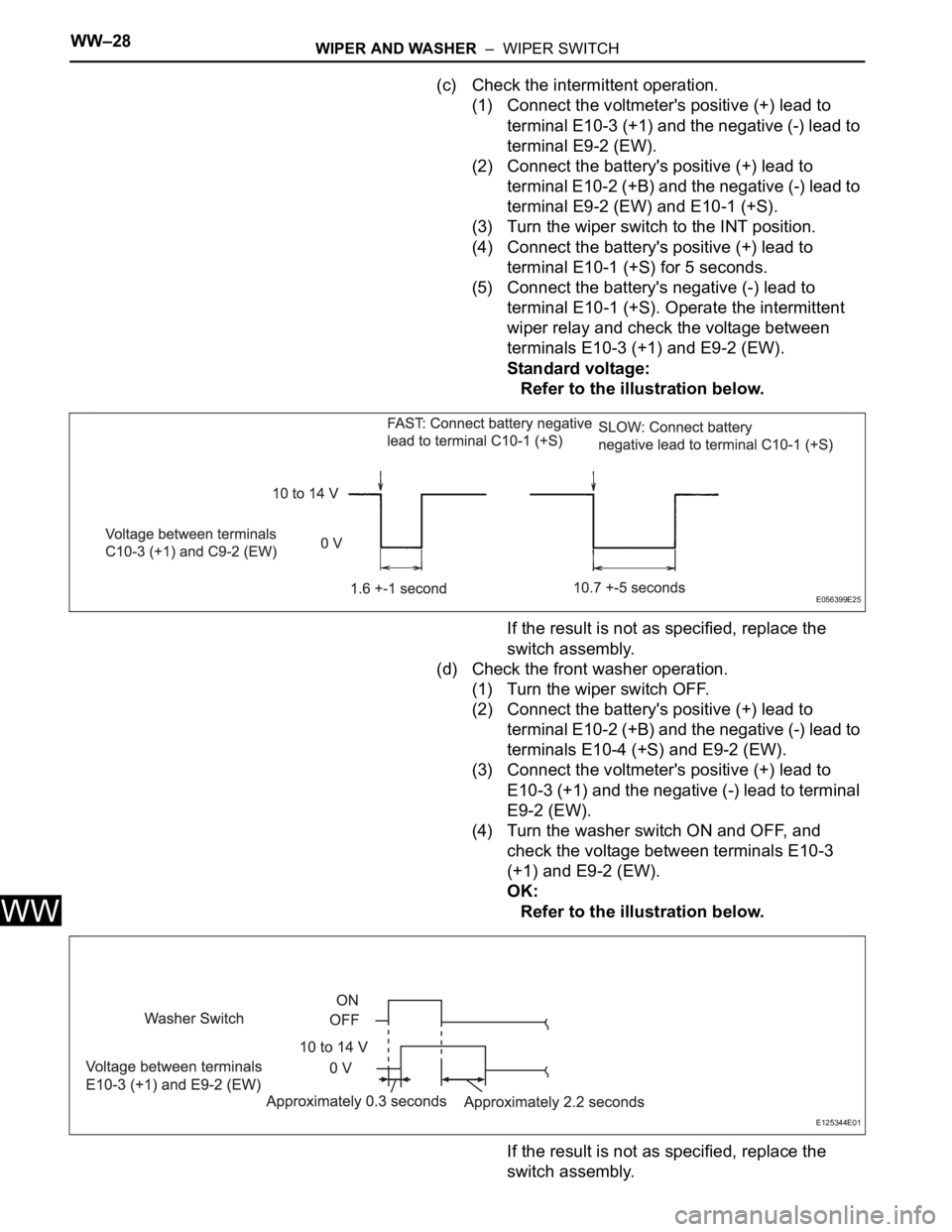
(c) Check the intermittent operation.
(1) Connect the voltmeter's positive (+) lead to
terminal E10-3 (+1) and the negative (-) lead to
terminal E9-2 (EW).
(2) Connect the battery's positive (+) lead to
terminal E10-2 (+B) and the negative (-) lead to
terminal E9-2 (EW) and E10-1 (+S).
(3) Turn the wiper switch to the INT position.
(4) Connect the battery's positive (+) lead to
terminal E10-1 (+S) for 5 seconds.
(5) Connect the battery's negative (-) lead to
terminal E10-1 (+S). Operate the intermittent
wiper relay and check the voltage between
terminals E10-3 (+1) and E9-2 (EW).
Standard voltage:
Refer to the illustration below.
If the result is not as specified, replace the
switch assembly.
(d) Check the front washer operation.
(1) Turn the wiper switch OFF.
(2) Connect the battery's positive (+) lead to
terminal E10-2 (+B) and the negative (-) lead to
terminals E10-4 (+S) and E9-2 (EW).
(3) Connect the voltmeter's positive (+) lead to
E10-3 (+1) and the negative (-) lead to terminal
E9-2 (EW).
(4) Turn the washer switch ON and OFF, and
check the voltage between terminals E10-3
(+1) and E9-2 (EW).
OK:
Refer to the illustration below.
If the result is not as specified, replace the
switch assembly.
E056399E25
E125344E01
Page 1898 of 2000
WIPER AND WASHER – WIPER SWITCHWW–29
WW
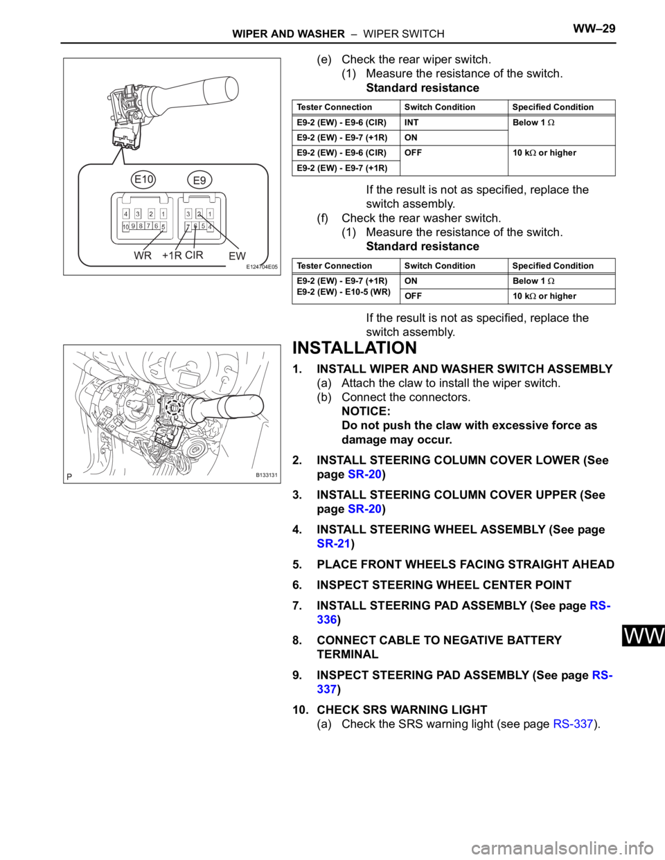
(e) Check the rear wiper switch.
(1) Measure the resistance of the switch.
Standard resistance
If the result is not as specified, replace the
switch assembly.
(f) Check the rear washer switch.
(1) Measure the resistance of the switch.
Standard resistance
If the result is not as specified, replace the
switch assembly.
INSTALLATION
1. INSTALL WIPER AND WASHER SWITCH ASSEMBLY
(a) Attach the claw to install the wiper switch.
(b) Connect the connectors.
NOTICE:
Do not push the claw with excessive force as
damage may occur.
2. INSTALL STEERING COLUMN COVER LOWER (See
page SR-20)
3. INSTALL STEERING COLUMN COVER UPPER (See
page SR-20)
4. INSTALL STEERING WHEEL ASSEMBLY (See page
SR-21)
5. PLACE FRONT WHEELS FACING STRAIGHT AHEAD
6. INSPECT STEERING WHEEL CENTER POINT
7. INSTALL STEERING PAD ASSEMBLY (See page RS-
336)
8. CONNECT CABLE TO NEGATIVE BATTERY
TERMINAL
9. INSPECT STEERING PAD ASSEMBLY (See page RS-
337)
10. CHECK SRS WARNING LIGHT
(a) Check the SRS warning light (see page RS-337).
E124704E05
Tester Connection Switch Condition Specified Condition
E9-2 (EW) - E9-6 (CIR) INT Below 1
E9-2 (EW) - E9-7 (+1R) ON
E9-2 (EW) - E9-6 (CIR) OFF 10 k
or higher
E9-2 (EW) - E9-7 (+1R)
Tester Connection Switch Condition Specified Condition
E9-2 (EW) - E9-7 (+1R)
E9-2 (EW) - E10-5 (WR)ON Below 1
OFF 10 k or higher
B133131
Page 1899 of 2000
WIPER AND WASHER – WASHER MOTORWW–33
WW
INSPECTION
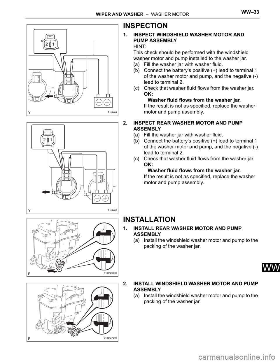
1. INSPECT WINDSHIELD WASHER MOTOR AND
PUMP ASSEMBLY
HINT:
This check should be performed with the windshield
washer motor and pump installed to the washer jar.
(a) Fill the washer jar with washer fluid.
(b) Connect the battery's positive (+) lead to terminal 1
of the washer motor and pump, and the negative (-)
lead to terminal 2.
(c) Check that washer fluid flows from the washer jar.
OK:
Washer fluid flows from the washer jar.
If the result is not as specified, replace the washer
motor and pump assembly.
2. INSPECT REAR WASHER MOTOR AND PUMP
ASSEMBLY
(a) Fill the washer jar with washer fluid.
(b) Connect the battery's positive (+) lead to terminal 1
of the washer motor and pump, and the negative (-)
lead to terminal 2.
(c) Check that washer fluid flows from the washer jar.
OK:
Washer fluid flows from the washer jar.
If the result is not as specified, replace the washer
motor and pump assembly.
INSTALLATION
1. INSTALL REAR WASHER MOTOR AND PUMP
ASSEMBLY
(a) Install the windshield washer motor and pump to the
packing of the washer jar.
2. INSTALL WINDSHIELD WASHER MOTOR AND PUMP
ASSEMBLY
(a) Install the windshield washer motor and pump to the
packing of the washer jar.
E114464
E114465
B133126E01
B133127E01
Page 1900 of 2000
WW–34WIPER AND WASHER – WASHER MOTOR
WW
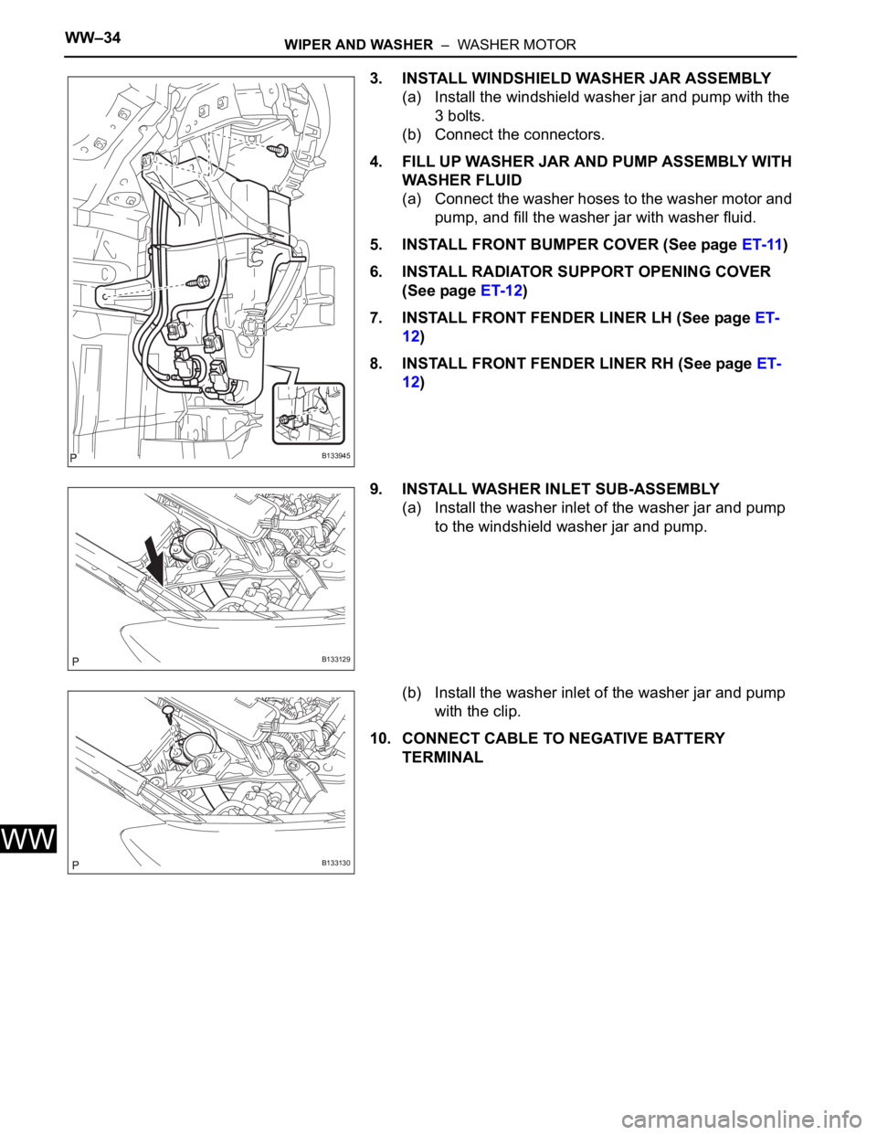
3. INSTALL WINDSHIELD WASHER JAR ASSEMBLY
(a) Install the windshield washer jar and pump with the
3 bolts.
(b) Connect the connectors.
4. FILL UP WASHER JAR AND PUMP ASSEMBLY WITH
WASHER FLUID
(a) Connect the washer hoses to the washer motor and
pump, and fill the washer jar with washer fluid.
5. INSTALL FRONT BUMPER COVER (See page ET-11)
6. INSTALL RADIATOR SUPPORT OPENING COVER
(See page ET-12)
7. INSTALL FRONT FENDER LINER LH (See page ET-
12)
8. INSTALL FRONT FENDER LINER RH (See page ET-
12)
9. INSTALL WASHER INLET SUB-ASSEMBLY
(a) Install the washer inlet of the washer jar and pump
to the windshield washer jar and pump.
(b) Install the washer inlet of the washer jar and pump
with the clip.
10. CONNECT CABLE TO NEGATIVE BATTERY
TERMINAL
B133945
B133129
B133130