Timing chain cover TOYOTA RAV4 2006 Service Repair Manual
[x] Cancel search | Manufacturer: TOYOTA, Model Year: 2006, Model line: RAV4, Model: TOYOTA RAV4 2006Pages: 2000, PDF Size: 45.84 MB
Page 1 of 2000

ENGINE - 2AZ-FE ENGINE EG-4
FEATURES OF 2AZ-FE ENGINE
The 2AZ-FE engine has achieved the following performance through the use of the items listed below.
(1) High performance and reliability
(2) Low noise and vibration
(3) Lightweight and compact design
(4) Good serviceability
(5) Clean emission and fuel economy
Section
Item(1)(2)(3)(4)(5)
Engine
A cylinder block made of aluminum alloy along with a
magnesium alloy die-cast cylinder head cover is used.
Engine
ProperA taper squish shape is used for the combustion chamber.p
A resin gear balance shaft is used.
Vl
A timing chain and chain tensioner are used.
Va l v e
MechanismThe shim-less type valve lifters are used.MechanismThe VVT-i system is used.
A chacoal filter is used in the air cleaner cap.
Intake andIntake manifold made of plastic is used.Intake and
ExhaustThe linkless-type throttle body is used.
SystemA thin-wall ceramic TWC (Three-Way Catalytic converter)
is used.
The fuel returnless system is used.
Fuel
System
Quick connectors are used to connect the fuel hose with the
fuel pipe.
System12-hole type fuel injectors with high atomizing performance
are used.
Ignition
SystemIridium-tipped spark plugs are used.
Charging
SystemThe segment conductor type generator is used.
Starting
SystemPS (Planetary reduction-Segment conductor motor) type
starter is used.
The ETCS-i is used.
Engine
Control
The DIS (Direct Ignition System) makes ignition timing
adjustment unnecessary.
Control
SystemThe non-contact type sensor is used in the throttle position
sensor.
The planar type air-fuel ratio sensor is used.
Page 10 of 2000

ENGINE - 2AZ-FE ENGINE
181EG11
VVT-i ControllerIntake CamshaftTiming Rotor
Exhaust Camshaft
Timing Sprocket
185EG25 181EG14
Cam Spring
Cam
Plunger
SpringChain
Te n s i o n e r
Chain Damper
Oil Jet
Chain TensionerChain SlipperEG-13
2. Camshaft
The intake camshaft is provided with timing rotor to trigger the camshaft position sensor.
In conjunction with the adoption of the VVT-i system, an oil passage is provided in the intake camshaft
in order to supply engine oil pressure to the VVT-i system.
A VVT-i controller has been installed on the front of the intake camshaft to vary the timing of the intake
valves.
3. Timing Chain
A roller chain with an 8 mm (0.315 in.) pitch is used to make the engine more compact.
The timing chain is lubricated by an oil jet.
The chain tensioner uses a spring and oil pressure to maintain proper chain tension at all times.
The chain tensioner suppresses noise generated by the timing chain.
A ratchet type non-return mechanism is used.
To achieve excellent serviceability, the chain tensioner is constructed so that it can be removed and
installed from the outside of the timing chain cover.
Page 79 of 2000

ENGINE - 2GR-FE ENGINE
285EG21
Timing Chain Cover
Wa t e r P u m p G a s k e t
Wa t e r P u m pWater Pump Swirl
Chamber
Oil Pump
Housing
Oil Pump RotorsTiming Chain
Cover
Oil Pump Chamber
View from Front Side View from Back Side
285EG22
Oil
Passage
Check Ball
Check Ball
Spring
Plunger SpringPlunger
Roller Rocker ArmCam
Oil
Passage
Hydraulic
Lash Adjuster
Service Tip
Valve clearance adjustment is not necessary because a hydraulic lash adjuster is used in this model.
EG-83
4. Timing Chain Cover
The timing chain cover has an integrated construction consisting of the cooling system (water pump and
water passage) and the lubrication system (oil pump and oil passage). Thus, the number of parts has been
reduced to reduce weight.
5. Hydraulic Lash Adjuster
The hydraulic lash adjuster, which is located at the fulcrum of the roller rocker arm, consists primarily of
a plunger, plunger spring, check ball, and check ball spring.
The engine oil that is supplied by the cylinder head and the built-in spring actuates the hydraulic lash
adjuster. The oil pressure and the spring force that act on the plunger push the roller rocker arm against
the cam, in order to adjust the valve clearance that is created during the opening and closing of the valve.
As a result, engine noise is reduced.
Page 82 of 2000
ENGINE - 2GR-FE ENGINE
285EG24
Timing Chain Cover
Oil Pump
Housing
Oil Pump Rotors
(Cycloid Rotor)Crankshaft
To Cylinder
Block
From Oil
Filter
To
Oil FilterFrom
Oil Strainer
Oil passage in the oil pump
285EG25
Oil Jet Cross Section
Oil JetsCheck
Va l v eEngine Oil EG-86
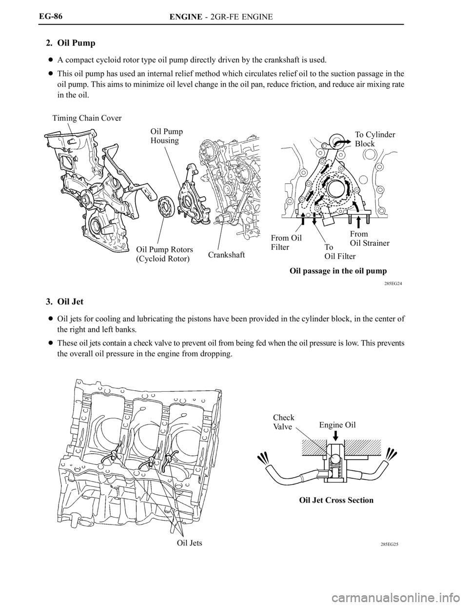
2. Oil Pump
A compact cycloid rotor type oil pump directly driven by the crankshaft is used.
This oil pump has used an internal relief method which circulates relief oil to the suction passage in the
oil pump. This aims to minimize oil level change in the oil pan, reduce friction, and reduce air mixing rate
in the oil.
3. Oil Jet
Oil jets for cooling and lubricating the pistons have been provided in the cylinder block, in the center of
the right and left banks.
These oil jets contain a check valve to prevent oil from being fed when the oil pressure is low. This prevents
the overall oil pressure in the engine from dropping.
Page 85 of 2000

ENGINE - 2GR-FE ENGINE
285EG29
Timing Chain Cover
Wa t e r P u m p G a s k e t
Wa t e r P u m pVolute ChambersFrom Water Inlet Housing
Rotor
View from Back Side
Cross SectionEG-89
Engine Coolant Specifications
Engine
Ty p e
TOYOTA genuine Super Long Life Coolant
(SLLC) or similar high quality ethylene glycol
based non-silicate, non-amine, non-nitrite and
non-borate coolant with long-life hybrid
organic acid technology (coolant with
long-life hybrid organic acid technology is a
combination of low phosphates and organic
acids.) Do not use plain water alone.
Engine
CoolantColorPink
Capacity
Except Towing
Package Models8.9 Liters (9.4 US qts, 7.8 Imp. qts)
CapacityTowing Package
Models9.2 Liters (9.7 US qts, 8.1 Imp. qts)
Maintenance IntervalsFirst Time100,000 miles (160,000 km)Maintenance IntervalsSubsequentEvery 50,000 miles (80,000 km)
SLLC is pre-mixed (the U.S.A. models: 50 % coolant and 50 % deionized water, the Canada. models: 55
% coolant and 45 % deionized water), so no dilution is needed when SLLC in the vehicle is added or
replaced.
If LLC is mixed with SLLC, the interval for LLC (every 25,000 miles (USA), 32,000 km (CANADA) or
24 months whichever comes first) should be used.
2. Water Pump
The water pump has two volute chambers, and circulates coolant uniformly to the left and right banks of the
cylinder block.
Page 249 of 2000
LU–142GR-FE LUBRICATION – OIL PUMP
LU
(c) Remove the 2 O-rings from the oil pump.
12. REMOVE WATER INLET HOUSING (See page CO-12)
13. REMOVE OIL PIPE (See page EM-52)
14. REMOVE CYLINDER HEAD COVER SUB-ASSEMBLY
(for Bank 1) (See page EM-52)
15. REMOVE NO. 1 OIL PIPE (See page EM-53)
16. REMOVE CYLINDER HEAD COVER SUB-ASSEMBLY
(for Bank 2) (See page EM-53)
17. REMOVE CRANKSHAFT PULLEY (See page EM-54)
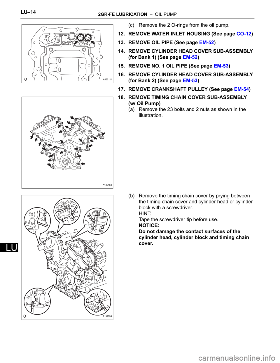
18. REMOVE TIMING CHAIN COVER SUB-ASSEMBLY
(w/ Oil Pump)
(a) Remove the 23 bolts and 2 nuts as shown in the
illustration.
(b) Remove the timing chain cover by prying between
the timing chain cover and cylinder head or cylinder
block with a screwdriver.
HINT:
Tape the screwdriver tip before use.
NOTICE:
Do not damage the contact surfaces of the
cylinder head, cylinder block and timing chain
cover.
A132111
A132150
A132099
Page 379 of 2000
SS–12SERVICE SPECIFICATIONS – 2AZ-FE ENGINE MECHANICAL
SS
TORQUE SPECIFICATIONS
DRIVE BELT
VALVE CLEARANCE
TIMING CHAIN
Part Tightened N*m kgf*cm ft.*lbf
Front suspension member
reinforcement RH x Front cross
member, Front suspension
crossmember96 979 71
Part Tightened N*m kgf*cm ft.*lbf
No. 1 camshaft bearing cap x
Cylinder head29.5 301 22
No. 2 camshaft bearing cap x
Cylinder head29.5 301 22
No. 3 camshaft bearing cap x
Cylinder head9.0 92 80 in.*lbf
No. 1 chain tensioner x Timing
chain cover9.0 92 80 in.*lbf
Part Tightened N*m kgf*cm ft.*lbf
Chain tensioner plate x Crankshaft bearing cap 12 122 9
Oil pump drive shaft sprocket x Oil pump 29.5 301 22
No. 1 chain vibration damper x Cylinder head,
Cylinder block9.0 92 80 in.*lbf
Chain tensioner slipper x Cylinder head, Cylinder
block19 194 14
Timing chain guide x Crankshaft bearing cap 9.0 92 80 in.*lbf
Timing chain cover x
Cylinder head, Cylinder
blockBolt A
(Head: 10 mm)9.0 92 80 in.*lbf
Bolt B
(Head: 12 mm)25 255 18
Bolt C
(Head: 14 mm)55 561 41
Nut 11 112 8
V-ribbed belt tensioner x Timing chain cover 59.5 607 44
Engine mounting bracket RH x Timing chain cover 55 561 41
Crankshaft pulley x Crankshaft 180 1,835 133
Oil pan x Stiffening
crankcaseBolt, Nut 9.0 92 80 in.*lbf
Cylinder head cover x
Cylinder headBolt A 11 112 8
Bolt B 14 143 10
Nut 11 112 8
Engine wire x Cylinder head cover 8.4 86 74 in.*lbf
Idler pulley bracket x Cylinder block 60 612 44
Engine mounting insulator FR x Front cross
member95 969 70
Engine mounting
insulator FRThrough bolt x Nut 145 1,479 107
Engine mounting insulator RH x Body 95 969 70
Engine mounting
insulator RH x Engine
mounting bracketNut A 95 969 70
Nut B 52 530 38
Radiator reservoir x Radiator support RH, Engine
mounting insulator RH5.0 51 44 in.*lbf
No. 1 engine cover x Cylinder head 7.0 71 62 in.*lbf
Page 383 of 2000

SERVICE SPECIFICATIONS – 2GR-FE ENGINE MECHANICALSS–21
SS
TORQUE SPECIFICATIONS
Part Tightened N*m kgf*cm ft.*lbf
Front suspension member reinforcement RH x Front
crossmember95 969 70
Front suspension member reinforcement RH x Front
suspension crossmember95 969 70
Radiator reservoir tank x Bract 5.0 51 44 in.*lbf
Engine coolant temperature sensor x Water outlet 20 204 14
Engine oil pressure sensor x Oil pan 21 214 15
No. 1 front engine mounting bracket LH x Timing chain
cover54 551 40
No. 2 idler pulley x Timing chain cover 43 438 32
No. 2 timing gear cover x Timing chain cover 6.0 61 53 in.*lbf
V-ribbed belt tensioner x Timing chain cover 43 438 32
V-ribbed belt tensioner x Cylinder block 43 438 32
Drive shaft bearing bracket x Cylinder block 64 653 47
Exhaust manifold LH x Cylinder head 21 214 15
No. 2 exhaust heat insulator x Exhaust manifold 8.5 87 75 in.*lbf
No. 2 manifold stay x Exhaust manifold 34 347 25
No. 2 manifold stay x Cylinder block 34 347 25
No. 1 oil dipstick guide x Cylinder block 21 214 15
No. 2 oil dipstick guide x Cylinder head 21 214 15
Exhaust manifold RH x Cylinder head 21 214 15
Intake manifold x Cylinder head 21 214 15
No. 2 engine mounting stay RH x Intake manifold 21 214 15
No. 2 engine mounting stay RH x Timing chain cover 21 214 15
Ignition coil x Cylinder head cover 10 102 7
Intake air surge tank x
Intake manifold5 mm hexagon wrench 18 184 13
for Bolt 21 214 15
for Nut 16 163 12
Vacuum hose clamp x Intake air surge tank 5.4 55 48 in.*lbf
Drive plate and ring gear x Crankshaft 178 1,815 132
Engine mounting bracket RR x Engine mounting
insulator RR95 969 70
Engine mounting bracket FR x Engine mounting
insulator FR145 1,479 107
Engine mounting bracket LH x Engine mounting
insulator LH56 571 41
Engine mounting insulator
RH x Front No. 1 engine
mounting bracketfor Bolt and nut A 95 969 70
for Nut B 52 530 38
Front crossmember x
Bodyfor Bolt A 96 979 71
Front suspension member
x Bodyfor Bolt B 145 1,478 107
Front suspension member
brace rear x Bodyfor Bolt C 145 1,478 107
for Bolt D 93 948 69
Air cleaner case x Engine mounting insulator LH 5.0 51 44 in.*lbf
Battery bracket reinforcement x Body 19 194 14
Front battery bracket x Body 19 194 14
Front battery bracket x Battery bracket reinforcement 19 194 14
Battery clamp x Body 5.0 51 44 in.*lbf
Page 384 of 2000
SS–22SERVICE SPECIFICATIONS – 2GR-FE ENGINE MECHANICAL
SS
Connecting rod x
Connecting cap1st 25 255 18
2nd Turn 90
Turn 90Turn 90
Cylinder block x
Crankshaft bearing cap1st 61 622 45
2nd Turn 90
Turn 90Turn 90
Main bearing cap bolt 52 530 38
Camshaft timing gear x Intake camshaft 100 1,020 74
Camshaft timing exhaust gear x Exhaust camshaft 100 1,020 74
Stud bolt x Cylinder block 10 102 7
Stud bolt x Cylinder head for Stud bolt A and B 10 102 7
for Stud bolt C 4.0 41 35 in.*lbf
No. 1 oil nozzle x Cylinder block 9.0 92 80
Cylinder block water drain
cock x Cylinder block1st 25 255 18
Adjusting position 45 or less 459 or less 33 or less
Water drain cock plug x Water drain cock 13 130 9
Crankshaft position sensor x Cylinder block 10 102 7
No. 2 straight screw plug x Cylinder head 80 816 59
No. 1 straight screw plug x Cylinder head 44 449 32
Water inlet pipe x Cylinder block 10 102 7
Cylinder head (for Bank 1)
x Cylinder block1st 36 367 27
2nd Turn 90
Turn 90Turn 90
3rd Turn 90Turn 90Turn 90
Cylinder head (for Bank2)
x Cylinder block1st 36 367 27
2nd Turn 90
Turn 90Turn 90
3rd Turn 90Turn 90Turn 90
Except bolt 30 306 22
Camshaft bearing cap x
Camshaft housing
(for Bank 1)1st 10 102 7
Camshaft housing x Cylinder head
(for Bank 1)28 286 21
Camshaft bearing cap x
Camshaft housing
(for Bank 1)2nd 16 163 12
Camshaft bearing cap x
Camshaft housing
(for Bank 2)1st 10 102 7
Camshaft housing x Cylinder head
(for Bank 2)28 286 21
Camshaft bearing cap x
Camshaft housing
(for Bank 2)2nd 16 163 12
No. 2 chain tensioner x Camshaft housing (for Bank 1) 21 214 15
No. 3 chain tensioner x Camshaft housing (for Bank 2) 21 214 15
No. 1 chain vibration damper x Cylinder block 23 235 17
Idle sprocket x Cylinder block 60 612 44
No. 1 chain tensioner x Cylinder block 10 102 7
Engine rear oil seal retainer x Cylinder block 10 102 7
Crankshaft pulley x Crankshaft 250 2,549 184
Oil pan baffle plate x Cylinder block 10 102 7
Front No. 1 engine mounting bracket x Timing chain
cover54 551 40 Part Tightened N*m kgf*cm ft.*lbf
Page 579 of 2000
EM–222AZ-FE ENGINE MECHANICAL – TIMING CHAIN
EM
REMOVAL
1. DISCONNECT CABLE FROM NEGATIVE BATTERY
TERMINAL
CAUTION:
Wait at least 90 seconds after disconnecting the
cable from the negative (-) battery terminal to
prevent airbag and seat belt pretensioner activation.
2. REMOVE RADIATOR SUPPORT OPENING COVER
3. REMOVE FRONT WHEEL RH
4. REMOVE NO. 1 ENGINE UNDER COVER
5. REMOVE FRONT FENDER APRON RH
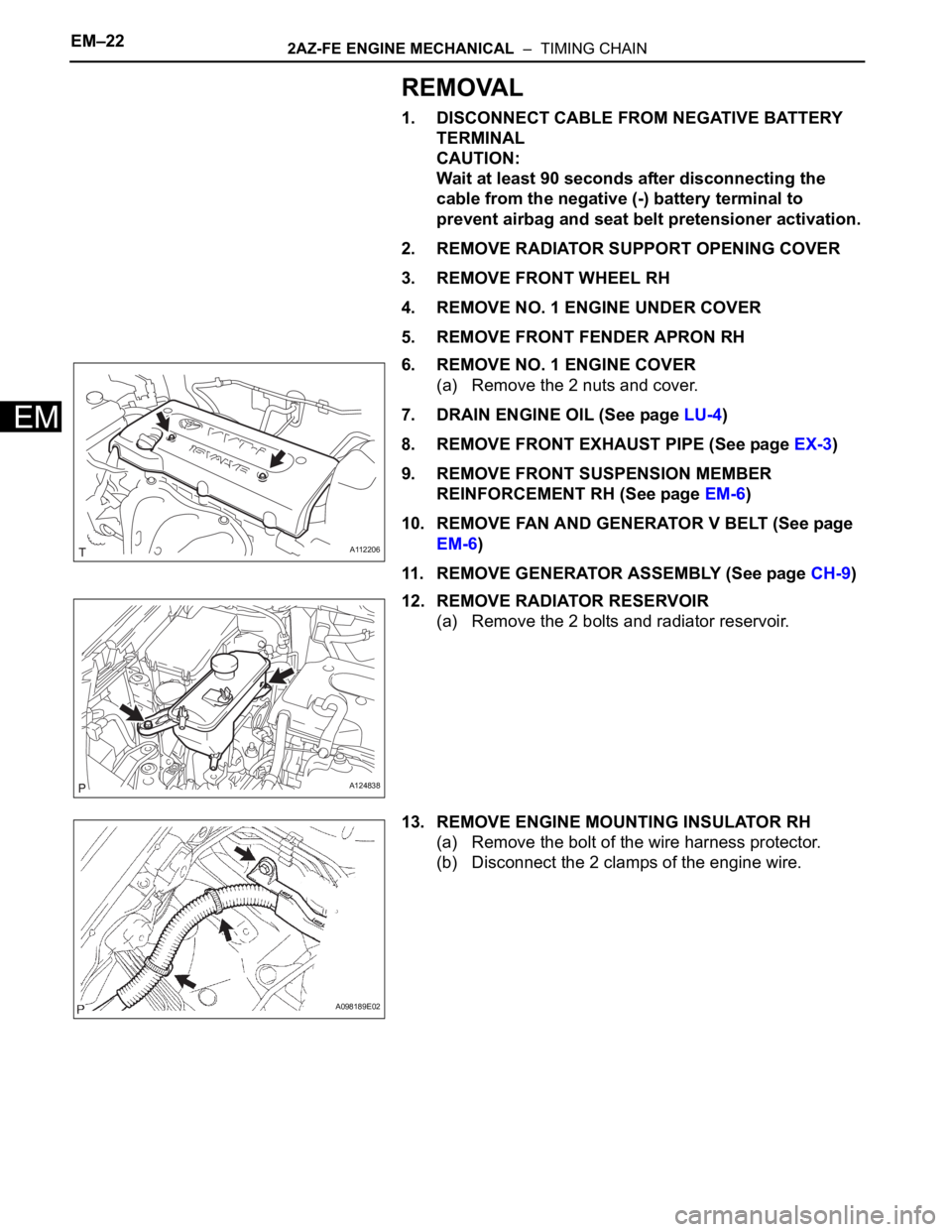
6. REMOVE NO. 1 ENGINE COVER
(a) Remove the 2 nuts and cover.
7. DRAIN ENGINE OIL (See page LU-4)
8. REMOVE FRONT EXHAUST PIPE (See page EX-3)
9. REMOVE FRONT SUSPENSION MEMBER
REINFORCEMENT RH (See page EM-6)
10. REMOVE FAN AND GENERATOR V BELT (See page
EM-6)
11. REMOVE GENERATOR ASSEMBLY (See page CH-9)
12. REMOVE RADIATOR RESERVOIR
(a) Remove the 2 bolts and radiator reservoir.
13. REMOVE ENGINE MOUNTING INSULATOR RH
(a) Remove the bolt of the wire harness protector.
(b) Disconnect the 2 clamps of the engine wire.
A112206
A124838
A098189E02