traction control TOYOTA RAV4 2006 Service Repair Manual
[x] Cancel search | Manufacturer: TOYOTA, Model Year: 2006, Model line: RAV4, Model: TOYOTA RAV4 2006Pages: 2000, PDF Size: 45.84 MB
Page 40 of 2000

ENGINE - 2AZ-FE ENGINE
00REG17Y
Accelerator Pedal
Position SensorThrottle Valve
Throttle Position SensorThrottle
Control
Motor
Mass Air
Flow MeterECMSkid
Control
ECU
Ignition
CoilFuel
Injector
: CANEG-43
6. ETCS-i (Electronic Throttle Control System-intelligent)
General
The ETCS-i is used, providing excellent throttle control in all the operating ranges. In the 2AZ-FE
engine, the accelerator cable has been discontinued, and an accelerator pedal position sensor has been
provided on the accelerator pedal.
In the conventional throttle body, the throttle valve opening is determined by the amount of the
accelerator pedal effort. In contrast, the ETCS-i uses the ECM to calculate the optimal throttle valve
opening that is appropriate for the respective driving condition and uses a throttle control motor to control
the opening.
The ETCS-i controls the IAC (Idle Air Control) system, the TRAC (Traction Control), VSC (Vehicle
Stability Control) system and curise control system.
In case of an abnormal condition, this system switches to the limp mode.
System Diagram
Page 114 of 2000

ENGINE - 2GR-FE ENGINE
01MEG18Y
Accelerator Pedal
Position SensorThrottle ValveThrottle Position Sensor
Throttle Control
Motor
Mass Air
Flow Meter
Cruise Control
Switch
Skid Control
ECUECMIgnition Coil
Fuel Injection EG-118
8. ETCS-i (Electronic Throttle Control System-intelligent)
General
In the conventional throttle body, the throttle valve angle is determined invariably by the amount of the
accelerator pedal effort. In contrast, ETCS-i uses the ECM to calculate the optimal throttle valve angle that
is appropriate for the respective driving condition and uses a throttle control motor to control the angle.
System Diagram
Control
1) General
The ETCS-i consists of the following five functions:
Normal Throttle Control (Non-linear Control)
IAC (Idle Air Control)
TRAC (Traction Control)
VSC (Vehicle Stability Control)
Cruise Control
Page 133 of 2000

CHASSIS - 4WD SYSTEM CH-66
4WD SYSTEM
DESCRIPTION
The 4WD system of the ’06 RAV4 uses an active torque control 4WD system.
It is a compact, lightweight, and high performance 4WD system that optimally controls the torque
distribution to the front and rear wheels through the electric control coupling in the rear differential.
ACTIVE TORQUE CONTROL 4WD SYSTEM
1. General
Based on information provided by various sensors, the 4WD ECU controls the amperage that is applied
to the electric control coupling, in order to transmit drive torque to the rear wheels when needed, and in
the amount needed. The following describes the features of the active torque control 4WD system.
Traction performance
Realizes stable start-off and acceleration performance
Driving stability performanceRealizes stable cornering performance
Fuel economyRealizes better fuel economy by transmitting drive torque to the rear
wheels when needed, in the amount needed.
A four-wheel drive lock switch has been provided. This enables the driver to select between the AUTO
and LOCK modes by operating the switch. The system optimally controls the torque distribution to the
front and rear wheels in the respective modes.
Mode
Four-wheel Drive
Lock Switch and
Indicator Light
Outline
AUTOOFF
Optimally distributes drive torque to the front and rear wheels.
Ensures optimal start-off performance during a start-off, based on
information provided by various sensors.
Suppresses the tight corner braking phenomenon* during low-speed
cornering.
Reduces the amount of torque distribution to the rear wheels and
improves fuel economy when the system judges that the vehicle is
traveling steadily.
Disengages the 4WD during braking deceleration.
LOCKON
Distributes the maximum torque limit to the rear wheels.
Distributes the maximum torque limit to the rear wheels during
start-off.
Distributes optimal torque during low-speed cornering.
Disengages the 4WD during braking deceleration.
Disengages the LOCK mode and transfers to the AUTO mode when
the vehicle speed exceeds 40 km / h (25 mph).
*: Tight corner braking phenomenon: a condition in which the brakes are applied due to a rotational difference
between the front and rear wheels, such as during low-speed cornering in the 4WD mode.
The 4WD ECU effects cooperative control with the skid control ECU, in order to control the drive torque
distribution to the front and rear wheels in accordance with information received from the skid control
ECU. These controls ensure a smooth acceleration and driving stability.
Page 1509 of 2000

BC–6BRAKE CONTROL – VEHICLE STABILITY CONTROL SYSTEM
BC
SYSTEM DESCRIPTION
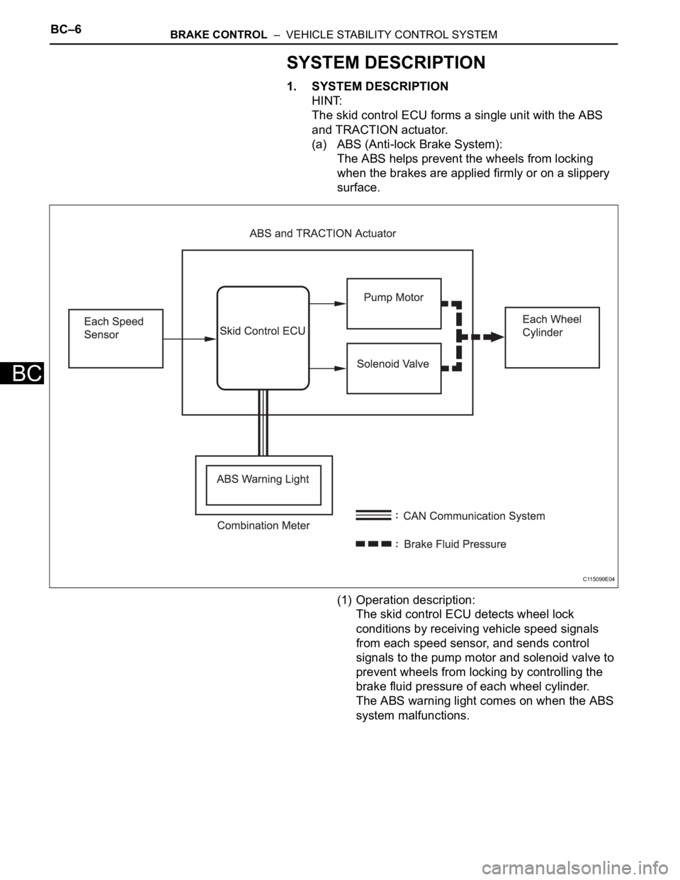
1. SYSTEM DESCRIPTION
HINT:
The skid control ECU forms a single unit with the ABS
and TRACTION actuator.
(a) ABS (Anti-lock Brake System):
The ABS helps prevent the wheels from locking
when the brakes are applied firmly or on a slippery
surface.
(1) Operation description:
The skid control ECU detects wheel lock
conditions by receiving vehicle speed signals
from each speed sensor, and sends control
signals to the pump motor and solenoid valve to
prevent wheels from locking by controlling the
brake fluid pressure of each wheel cylinder.
The ABS warning light comes on when the ABS
system malfunctions.
C115099E04
Page 1512 of 2000

BRAKE CONTROL – VEHICLE STABILITY CONTROL SYSTEMBC–9
BC
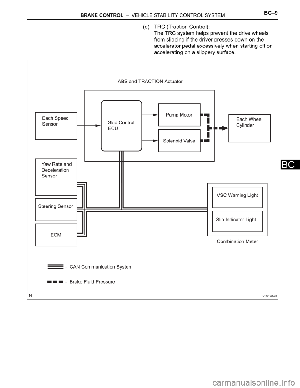
(d) TRC (Traction Control):
The TRC system helps prevent the drive wheels
from slipping if the driver presses down on the
accelerator pedal excessively when starting off or
accelerating on a slippery surface.
C115102E02
Page 1518 of 2000

BRAKE CONTROL – VEHICLE STABILITY CONTROL SYSTEMBC–15
BC
(1) Operation description:
When the system is in operation, the following
occurs: 1) the slip indicator light blinks; 2) the
VSC light comes on; and 3) when hill-start assist
control operation starts, the skid control buzzer
sounds once; when hill-start assist control
operation ends, the skid control buzzer sounds
twice.
The VSC warning light comes on when the hill-
start assist control is malfunctioning.
(h) AUTO LSD (Auto Limited Slip Differential) for 2WD:
The AUTO LSD achieves the equivalent functions of
an LSD (Limited Slip Differential) through the use of
a traction control system. When the driver presses
the AUTO LSD switch, this system achieves the
LSD effect by regulating the hydraulic pressure that
acts on the drive wheels and controlling the engine
output in accordance with the amount of pedal effort
applied on the accelerator. The AUTO LSD
operates with the AUTO LSD switch on and the
accelerator pedal depressed.
Auto LSD restrains brake pressure and reduces
differential movement, thus transmitting the drive
torque to the other drive wheel to ensure stability
under the following conditions:
• Wheels run off the road.
• Drive wheels spin in place when starting on a
slope with one wheel on snow/ice.
HINT:
Releasing the accelerator pedal cancels control of
the AUTO LSD system.
Page 1521 of 2000

BC–18BRAKE CONTROL – VEHICLE STABILITY CONTROL SYSTEM
BC
(3) Front Wheel Skid Tendency
When the skid control ECU determines that
there is a front wheel skid tendency, it controls
the VSC to dampen the front wheel skid. At the
same time, it effects cooperative control with the
EPS to provide steering torque assist, which
facilitates the driver's steering maneuvers to
stabilize the vehicle posture. To prevent
excessive steering maneuvers, it provides a
steering torque assist. This assist increases the
resistance to counter the driver's steering effort,
if the driver turns the steering wheel excessively.
(4) Rear Wheel Skid Tendency
When the skid control ECU determines that
there is a rear wheel skid tendency, it controls
the VSC to dampen the rear wheel skid. At the
same time, it effects cooperative control with the
EPS to provide steering torque assist, which
facilitates the driver's steering maneuvers in the
direction to correct the rear wheel skid.
(5) Acceleration During Cornering
A sudden acceleration of the vehicle during
cornering may cause a drive wheel to freewheel,
which could cause the front wheels or rear
wheels to skid. If the skid control ECU
determines that there is freewheeling of a drive
wheel, a front wheel skid tendency, or a rear
wheel skid tendency, it effects cooperative
control with the 4WD system to optimally control
the drive torque distribution to the front and rear
wheels. Furthermore, it controls the TRC and
the VSC as needed to ensure driving stability
and acceleration performance.
(b) Operation
The operation of the solenoid valves under the
cooperative control is the same as the TRC or VSC
operation.
3. ABS WITH EBD, BA, TRC AND VSC OPERATION
(a) The skid control ECU calculates vehicle stability
tendency based on the signals from the 4 wheel
speed sensors, the yaw rate and deceleration
sensor and the steering sensor. In addition, it
evaluates the results of the calculations to
determine whether any control actions (control of
the engine output torque by electronic throttle
control and of the brake fluid pressure by the ABS
and TRACTION actuator) should be implemented.
(b) The slip indicator blinks and the skid control buzzer
sounds to inform the driver that the VSC system is
operating. The slip indicator also blinks when
traction control is operating, and the operation being
performed is displayed.
Page 1522 of 2000

BRAKE CONTROL – VEHICLE STABILITY CONTROL SYSTEMBC–19
BC
4. FAIL SAFE FUNCTION
(a) When a failure occurs in the ABS with BA, TRC and
VSC systems, the ABS and VSC warning lights
illuminate, the slip indicator light comes on*1 or
remains off*2, and the operations of those systems
are prohibited. In addition to this, when a failure
which disables the EBD operation occurs, the brake
warning light comes on and its operation is
prohibited.
HINT:
*1: for 2WD
*2: for 4WD
(b) If control is prohibited due to a malfunction during
operation, control is disabled gradually to avoid
sudden vehicle instability.
5. INITIAL CHECK
(a) When the vehicle speed first reaches approximately
6 km/h (4 mph) or more after the ignition switch is
turned ON, each solenoid valve and the motor of the
ABS and TRACTION actuator are sequentially
activated to perform electrical checks. During the
initial check, the operating sound of the solenoid
valve and motor can be heard from the engine
compartment, but this does not indicate a
malfunction.
6. SERVICE MODE
(a) VSC operation can be disabled by operating the
intelligent tester.
HINT:
Refer to the intelligent tester operator's manual for
further details.
7. FUNCTION OF COMPONENTS
Components Functions
Speed Sensor
(Semiconductor Type)Detects the wheel speed and sends the signal to skid
control ECU
Skid Control ECU
(Housed in ABS and TRACTION Actuator)• Processes the signals from each sensor to control the
ABS, BA, TRC, and VSC
• Sends and receives control signals to and from the
ECM, yaw rate and deceleration sensor, steering
sensor, etc. via CAN communication.
ABS and TRACTION Actuator • Consists of the master cylinder cut solenoid valve,
holding solenoid valve, pressure reduction solenoid
valve, pump motor, and reservoir, and adjusts the brake
fluid pressure applied to each wheel cylinder
• Houses the skid control ECU
Solenoid Relay • Supplies power to each solenoid
• Housed in the skid control ECU
Motor Relay (VSC MTR Relay) • Supplies power to the pump motor
• Installed in engine room No. 1 relay block
Fail-safe Relay (VSC FAIL Relay) • Cuts off power to the motor when the pump motor circuit
malfunctions
• Installed in engine room No. 1 relay block
Page 1523 of 2000

BC–20BRAKE CONTROL – VEHICLE STABILITY CONTROL SYSTEM
BC
HINT:
*1: w/ Downhill assist control
*2: for 2WD w/ AUTO LSD
Steering Sensor • Detects the steering extent and direction and sends
signals to the skid control ECU via CAN communication
• Has a magnetic resistance element which detects the
rotation of the magnet housed in the detection gear in
order to detect the changes in magnetic resistance and
the steering amount and direction
Yaw Rate and Deceleration Sensor • Yaw rate sensor detects the vehicle's angular velocity
(yaw rate) in the vertical direction based on the extent
and direction of the deflection of the piezoelectric
ceramics
• Deceleration sensor measures the capacity of the
condenser that changes the distance between the
electrodes depending on G force, which occurs when
the vehicle is accelerated, and converts the measured
value into electrical signals
• Sends signals to the skid control ECU via CAN
communication
Master Cylinder Pressure Sensor • Detects the brake fluid pressure in the master cylinder
• Housed in the ABS and TRACTION actuator
ECM• Controls the engine output when TRC and VSC are
operating with the skid control ECU via CAN
communication
Downhill Assist Control switch*1 Allows the driver to turn downhill assist control ON and OFF
AUTO LSD switch*2 Allows the driver to turn AUTO LSD ON and OFF
Combination Meter ABS Warning Light • Illuminates to inform the driver that a malfunction in the
ABS has occurred
• Blinks to indicate DTCs that relate to the ABS
VSC Warning Light • Illuminates to inform the driver that a malfunction in the
VSC system has occurred
• Blinks to indicate DTCs that relate to the VSC
Brake Warning light • Illuminates to inform the driver that the parking brake is
ON when the system is normal, and when the brake
fluid has decreased
• Illuminates to inform the driver that a malfunction in the
EBD has occurred
Slip Indicator Light • Blinks to inform the driver that TRC, VSC, downhill
assist control and hill-start assist control are operating
• Illuminates to inform the driver that a malfunction has
occurred in the TRC or VSC system
AUTO LSD Indicator Light*2 Lights up to inform the driver when AUTO LSD operation is
possible
Downhill Assist Control Indicator
Light*1Lights up to inform the driver when downhill assist control
operation is possible
Skid Control Buzzer • Intermittently sounds to inform the driver that the VSC is
operating
• Housed in the combination meter Components Functions
Page 1545 of 2000

BC–42BRAKE CONTROL – VEHICLE STABILITY CONTROL SYSTEM
BC
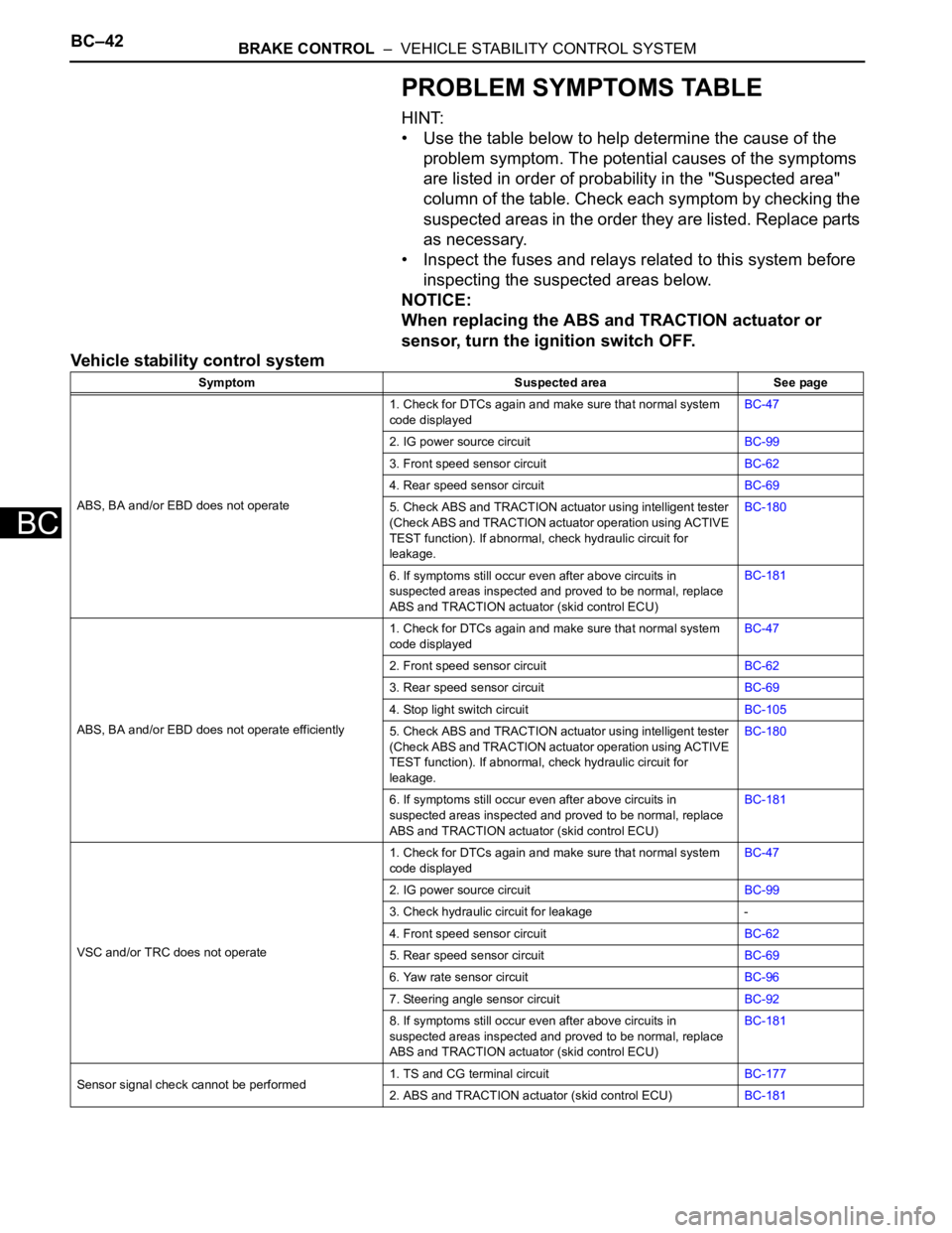
PROBLEM SYMPTOMS TABLE
HINT:
• Use the table below to help determine the cause of the
problem symptom. The potential causes of the symptoms
are listed in order of probability in the "Suspected area"
column of the table. Check each symptom by checking the
suspected areas in the order they are listed. Replace parts
as necessary.
• Inspect the fuses and relays related to this system before
inspecting the suspected areas below.
NOTICE:
When replacing the ABS and TRACTION actuator or
sensor, turn the ignition switch OFF.
Vehicle stability control system
Symptom Suspected area See page
ABS, BA and/or EBD does not operate1. Check for DTCs again and make sure that normal system
code displayedBC-47
2. IG power source circuitBC-99
3. Front speed sensor circuitBC-62
4. Rear speed sensor circuitBC-69
5. Check ABS and TRACTION actuator using intelligent tester
(Check ABS and TRACTION actuator operation using ACTIVE
TEST function). If abnormal, check hydraulic circuit for
leakage.BC-180
6. If symptoms still occur even after above circuits in
suspected areas inspected and proved to be normal, replace
ABS and TRACTION actuator (skid control ECU)BC-181
ABS, BA and/or EBD does not operate efficiently1. Check for DTCs again and make sure that normal system
code displayedBC-47
2. Front speed sensor circuitBC-62
3. Rear speed sensor circuitBC-69
4. Stop light switch circuitBC-105
5. Check ABS and TRACTION actuator using intelligent tester
(Check ABS and TRACTION actuator operation using ACTIVE
TEST function). If abnormal, check hydraulic circuit for
leakage.BC-180
6. If symptoms still occur even after above circuits in
suspected areas inspected and proved to be normal, replace
ABS and TRACTION actuator (skid control ECU)BC-181
VSC and/or TRC does not operate1. Check for DTCs again and make sure that normal system
code displayedBC-47
2. IG power source circuitBC-99
3. Check hydraulic circuit for leakage -
4. Front speed sensor circuitBC-62
5. Rear speed sensor circuitBC-69
6. Yaw rate sensor circuitBC-96
7. Steering angle sensor circuitBC-92
8. If symptoms still occur even after above circuits in
suspected areas inspected and proved to be normal, replace
ABS and TRACTION actuator (skid control ECU)BC-181
Sensor signal check cannot be performed1. TS and CG terminal circuitBC-177
2. ABS and TRACTION actuator (skid control ECU)BC-181