Wheel bearing TOYOTA RAV4 2006 Service Repair Manual
[x] Cancel search | Manufacturer: TOYOTA, Model Year: 2006, Model line: RAV4, Model: TOYOTA RAV4 2006Pages: 2000, PDF Size: 45.84 MB
Page 199 of 2000

EM–242GR-FE ENGINE MECHANICAL – ENGINE ASSEMBLY
EM
(b) 4WD:
Disconnect the control cable (see page AX-154).
31. REMOVE FRONT EXHAUST PIPE ASSEMBLY (See
page EX-3)
32. REMOVE CENTER EXHAUST PIPE ASSEMBLY (See
page EX-2)
33. REMOVE PROPELLER WITH CENTER BEARING
SHAFT ASSEMBLY (See page PR-3)
34. REMOVE FRONT WHEELS
35. REMOVE FRONT AXLE HUB NUT LH
(a) Remove the hub nut (see page AH-8).
36. REMOVE FRONT AXLE HUB NUT RH
(a) Remove the hub nut (see page AH-8).
37. DISCONNECT FRONT STABILIZER LINK ASSEMBLY
LH (See page SP-30)
38. DISCONNECT FRONT STABILIZER LINK ASSEMBLY
RH (See page SP-30)
39. DISCONNECT STEERING INTERMEDIATE SHAFT
(See page PS-44)
40. DISCONNECT TIE ROD END SUB-ASSEMBLY RH
(See page PS-42)
41. DISCONNECT TIE ROD END SUB-ASSEMBLY LH
(See page PS-42)
42. REMOVE FRONT DRIVE SHAFT LH
(a) 2WD:
Remove the drive shaft (see page DS-10).
(b) 4WD:
Remove the drive shaft (see page DS-43).
43. REMOVE FRONT DRIVE SHAFT RH
(a) 2WD:
Remove the drive shaft (see page DS-10).
(b) 4WD:
Remove the drive shaft (see page DS-43).
44. REMOVE ENGINE WITH TRANSAXLE
(a) Install the No. 1 and No. 2 engine hangers with the
4 bolts as shown in the illustration.
Torque: 33 N*m (337 kgf*cm, 24 ft.*lbf)
HINT:
• Insert the claw of the hanger into hole of the
cylinder head.
• Fit the fork part of the hanger onto the rib of the
cylinder head.
A129635E02
Part Name Part No.
No. 1 engine hanger 12281-31120
No. 2 engine hanger 12282-31100
Bolt 91671-10825
Page 393 of 2000
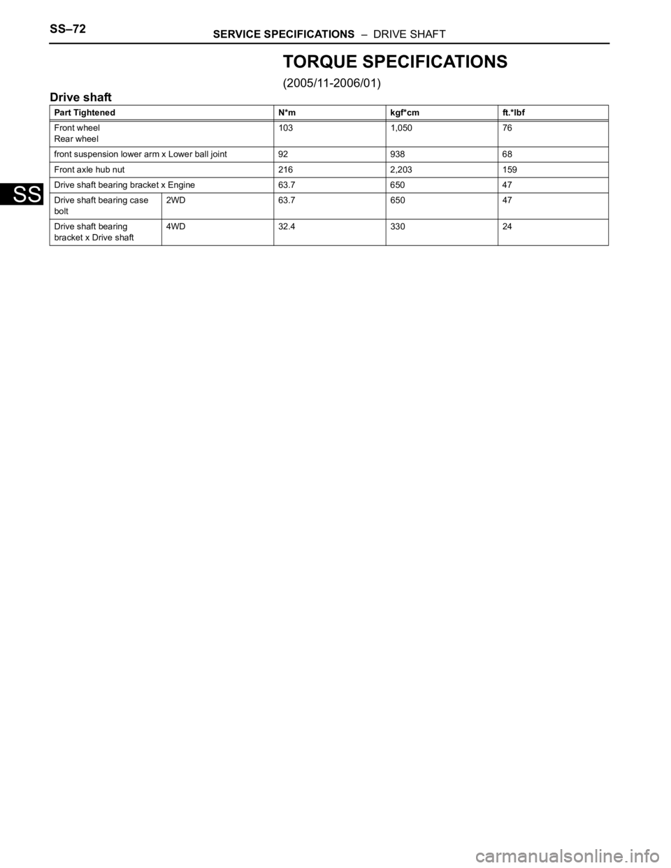
SS–72SERVICE SPECIFICATIONS – DRIVE SHAFT
SS
TORQUE SPECIFICATIONS
(2005/11-2006/01)
Drive shaft
Part Tightened N*m kgf*cm ft.*lbf
Front wheel
Rear wheel103 1,050 76
front suspension lower arm x Lower ball joint 92 938 68
Front axle hub nut 216 2,203 159
Drive shaft bearing bracket x Engine 63.7 650 47
Drive shaft bearing case
bolt2WD 63.7 650 47
Drive shaft bearing
bracket x Drive shaft4WD 32.4 330 24
Page 394 of 2000
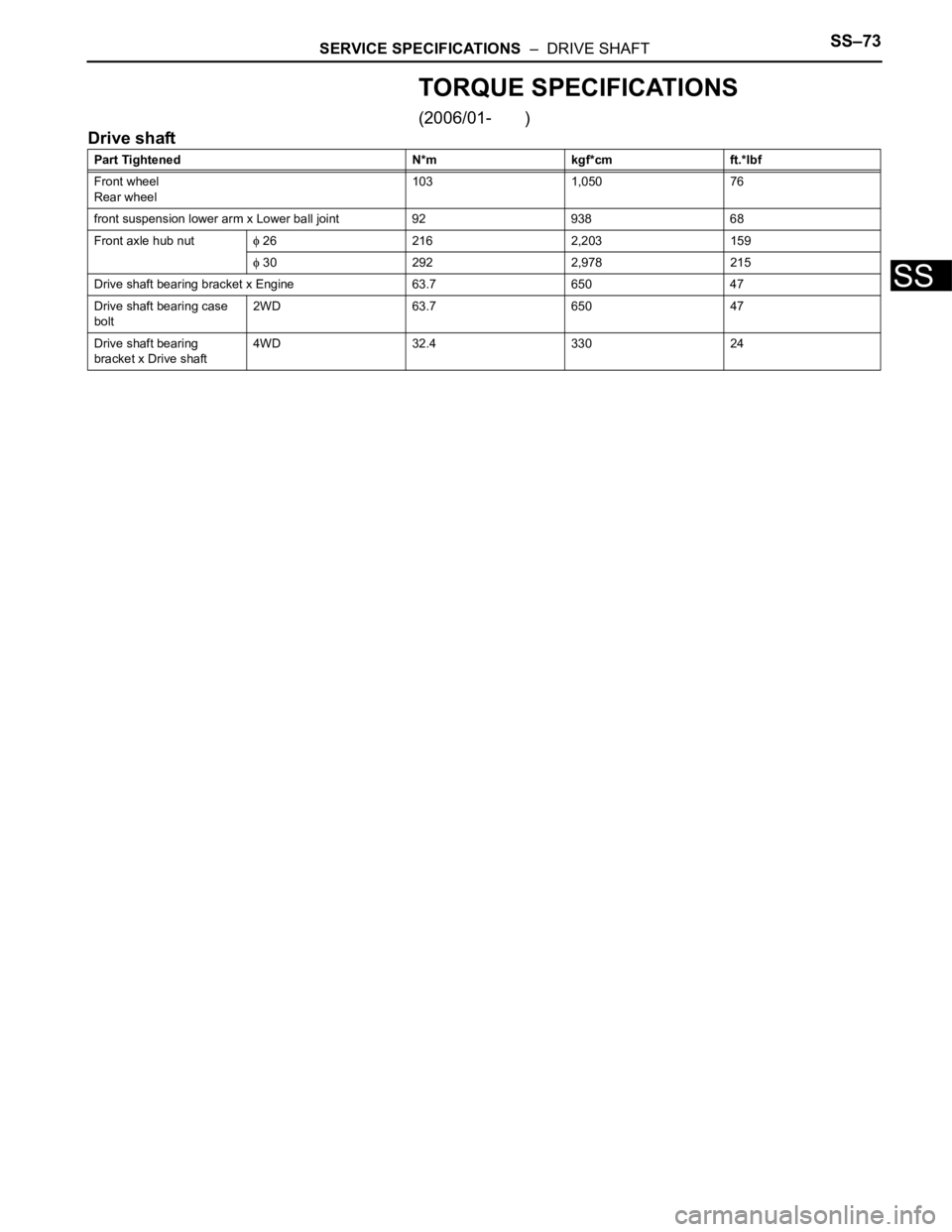
SERVICE SPECIFICATIONS – DRIVE SHAFTSS–73
SS
TORQUE SPECIFICATIONS
(2006/01- )
Drive shaft
Part Tightened N*m kgf*cm ft.*lbf
Front wheel
Rear wheel103 1,050 76
front suspension lower arm x Lower ball joint 92 938 68
Front axle hub nut
26 216 2,203 159
30 292 2,978 215
Drive shaft bearing bracket x Engine 63.7 650 47
Drive shaft bearing case
bolt2WD 63.7 650 47
Drive shaft bearing
bracket x Drive shaft4WD 32.4 330 24
Page 403 of 2000
AH–6AXLE – FRONT AXLE HUB
AH
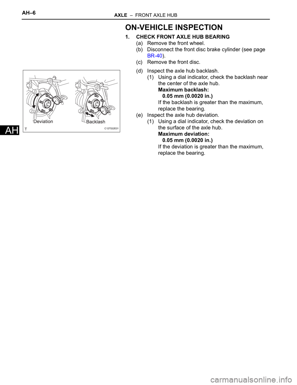
ON-VEHICLE INSPECTION
1. CHECK FRONT AXLE HUB BEARING
(a) Remove the front wheel.
(b) Disconnect the front disc brake cylinder (see page
BR-40).
(c) Remove the front disc.
(d) Inspect the axle hub backlash.
(1) Using a dial indicator, check the backlash near
the center of the axle hub.
Maximum backlash:
0.05 mm (0.0020 in.)
If the backlash is greater than the maximum,
replace the bearing.
(e) Inspect the axle hub deviation.
(1) Using a dial indicator, check the deviation on
the surface of the axle hub.
Maximum deviation:
0.05 mm (0.0020 in.)
If the deviation is greater than the maximum,
replace the bearing.
C127532E01
Page 421 of 2000
STEERING COLUMN – STEERING SYSTEMSR–3
SR
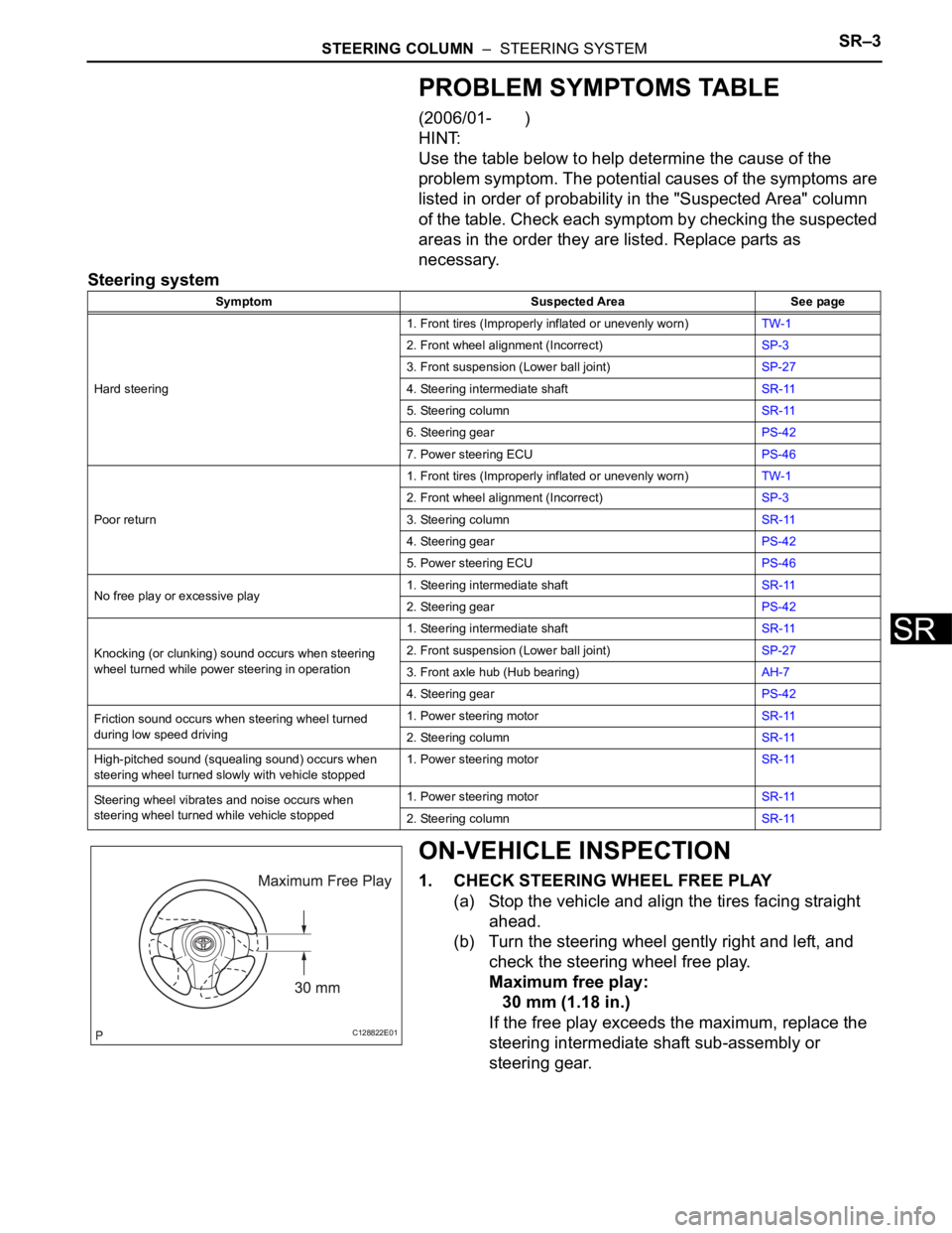
PROBLEM SYMPTOMS TABLE
(2006/01- )
HINT:
Use the table below to help determine the cause of the
problem symptom. The potential causes of the symptoms are
listed in order of probability in the "Suspected Area" column
of the table. Check each symptom by checking the suspected
areas in the order they are listed. Replace parts as
necessary.
Steering system
ON-VEHICLE INSPECTION
1. CHECK STEERING WHEEL FREE PLAY
(a) Stop the vehicle and align the tires facing straight
ahead.
(b) Turn the steering wheel gently right and left, and
check the steering wheel free play.
Maximum free play:
30 mm (1.18 in.)
If the free play exceeds the maximum, replace the
steering intermediate shaft sub-assembly or
steering gear.
Symptom Suspected Area See page
Hard steering1. Front tires (Improperly inflated or unevenly worn)TW-1
2. Front wheel alignment (Incorrect)SP-3
3. Front suspension (Lower ball joint)SP-27
4. Steering intermediate shaftSR-11
5. Steering columnSR-11
6. Steering gearPS-42
7. Power steering ECUPS-46
Poor return1. Front tires (Improperly inflated or unevenly worn)TW-1
2. Front wheel alignment (Incorrect)SP-3
3. Steering columnSR-11
4. Steering gearPS-42
5. Power steering ECUPS-46
No free play or excessive play1. Steering intermediate shaftSR-11
2. Steering gearPS-42
Knocking (or clunking) sound occurs when steering
wheel turned while power steering in operation1. Steering intermediate shaftSR-11
2. Front suspension (Lower ball joint)SP-27
3. Front axle hub (Hub bearing)AH-7
4. Steering gearPS-42
Friction sound occurs when steering wheel turned
during low speed driving1. Power steering motorSR-11
2. Steering columnSR-11
High-pitched sound (squealing sound) occurs when
steering wheel turned slowly with vehicle stopped1. Power steering motorSR-11
Steering wheel vibrates and noise occurs when
steering wheel turned while vehicle stopped1. Power steering motorSR-11
2. Steering columnSR-11
C128822E01
Page 684 of 2000
EM–382GR-FE ENGINE MECHANICAL – ENGINE ASSEMBLY
EM
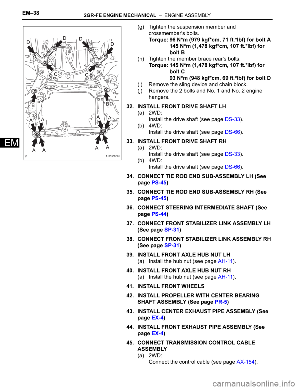
(g) Tighten the suspension member and
crossmember's bolts.
Torque: 96 N*m (979 kgf*cm, 71 ft.*lbf) for bolt A
145 N*m (1,478 kgf*cm, 107 ft.*lbf) for
bolt B
(h) Tighten the member brace rear's bolts.
Torque: 145 N*m (1,478 kgf*cm, 107 ft.*lbf) for
bolt C
93 N*m (948 kgf*cm, 69 ft.*lbf) for bolt D
(i) Remove the sling device and chain block.
(j) Remove the 2 bolts and No. 1 and No. 2 engine
hangers.
32. INSTALL FRONT DRIVE SHAFT LH
(a) 2WD:
Install the drive shaft (see page DS-33).
(b) 4WD:
Install the drive shaft (see page DS-66).
33. INSTALL FRONT DRIVE SHAFT RH
(a) 2WD:
Install the drive shaft (see page DS-33).
(b) 4WD:
Install the drive shaft (see page DS-66).
34. CONNECT TIE ROD END SUB-ASSEMBLY LH (See
page PS-45)
35. CONNECT TIE ROD END SUB-ASSEMBLY RH (See
page PS-45)
36. CONNECT STEERING INTERMEDIATE SHAFT (See
page PS-44)
37. CONNECT FRONT STABILIZER LINK ASSEMBLY LH
(See page SP-31)
38. CONNECT FRONT STABILIZER LINK ASSEMBLY RH
(See page SP-31)
39. INSTALL FRONT AXLE HUB NUT LH
(a) Install the hub nut (see page AH-11).
40. INSTALL FRONT AXLE HUB NUT RH
(a) Install the hub nut (see page AH-11).
41. INSTALL FRONT WHEELS
42. INSTALL PROPELLER WITH CENTER BEARING
SHAFT ASSEMBLY (See page PR-5)
43. INSTALL CENTER EXHAUST PIPE ASSEMBLY (See
page EX-4)
44. INSTALL FRONT EXHAUST PIPE ASSEMBLY (See
page EX-4)
45. CONNECT TRANSMISSION CONTROL CABLE
ASSEMBLY
(a) 2WD:
Connect the control cable (see page AX-154).
A123580E01
Page 1389 of 2000
DRIVE SHAFT – FRONT DRIVE SHAFT ASSEMBLY (for 2WD)DS–33
DS
12. CONNECT FRONT SPEED SENSOR RH
HINT:
Use the same procedures described for the LH side.
13. INSTALL FRONT AXLE HUB NUT (See page AH-10)
14. INSTALL FRONT WHEEL
Torque: 103 N*m (1,050 kgf*cm, 76 ft.*lbf)
15. ADD AUTOMATIC TRANSAXLE FLUID
(a) Add automatic transaxle fluid for U140F (see page
AX-152).
(b) Add automatic transaxle fluid for U241E (see page
AX-151).
16. CHECK FOR AUTOMATIC TRANSAXLE OIL
LEAKAGE
17. INSPECT AND ADJUST FRONT WHEEL ALIGNMENT
(a) Inspect and adjust the front wheel alignment (see
page SP-3).
INSTALLATION
(2006/01- )
1. INSTALL FRONT DRIVE SHAFT ASSEMBLY LH
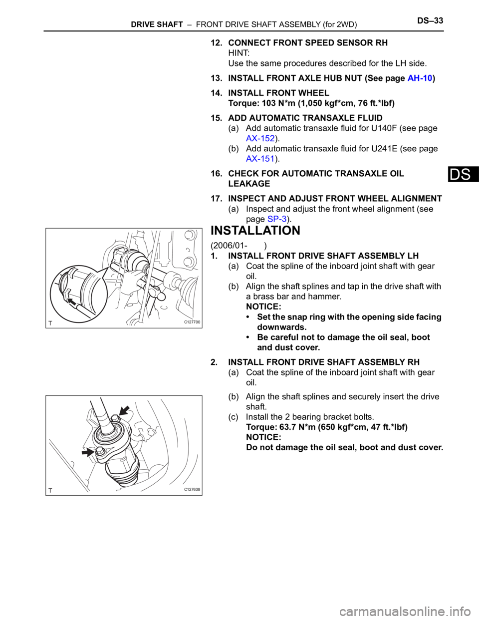
(a) Coat the spline of the inboard joint shaft with gear
oil.
(b) Align the shaft splines and tap in the drive shaft with
a brass bar and hammer.
NOTICE:
• Set the snap ring with the opening side facing
downwards.
• Be careful not to damage the oil seal, boot
and dust cover.
2. INSTALL FRONT DRIVE SHAFT ASSEMBLY RH
(a) Coat the spline of the inboard joint shaft with gear
oil.
(b) Align the shaft splines and securely insert the drive
shaft.
(c) Install the 2 bearing bracket bolts.
Torque: 63.7 N*m (650 kgf*cm, 47 ft.*lbf)
NOTICE:
Do not damage the oil seal, boot and dust cover.
C127700
C127638
Page 1420 of 2000
DS–66DRIVE SHAFT – FRONT DRIVE SHAFT ASSEMBLY (for 4WD)
DS
12. CONNECT FRONT SPEED SENSOR RH
HINT:
Use the same procedures described for the LH side.
13. INSTALL FRONT AXLE HUB NUT (See page AH-10)
14. INSTALL FRONT WHEEL
Torque: 103 N*m (1,050 kgf*cm, 76 ft.*lbf)
15. ADD AUTOMATIC TRANSAXLE FLUID
(a) Add automatic transaxle fluid for U140F (see page
AX-152).
(b) Add automatic transaxle fluid for U241E (see page
AX-151).
16. CHECK FOR AUTOMATIC TRANSAXLE FLUID
LEAKAGE
17. INSPECT AND ADJUST FRONT WHEEL ALIGNMENT
(a) Inspect and adjust front wheel alignment (see page
SP-3).
INSTALLATION
(2006/01- )
1. INSTALL FRONT DRIVE SHAFT ASSEMBLY LH
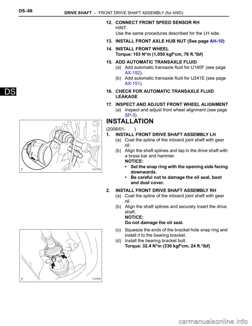
(a) Coat the spline of the inboard joint shaft with gear
oil.
(b) Align the shaft splines and tap in the drive shaft with
a brass bar and hammer.
NOTICE:
• Set the snap ring with the opening side facing
downwards.
• Be careful not to damage the oil seal, boot
and dust cover.
2. INSTALL FRONT DRIVE SHAFT ASSEMBLY RH
(a) Coat the spline of the inboard joint shaft with gear
oil.
(b) Align the shaft splines and securely insert the drive
shaft.
NOTICE:
Do not damage the oil seal.
(c) Squeeze the ends of the bracket hole snap ring and
install it to the bearing bracket.
(d) Install the bearing bracket bolt.
Torque: 32.4 N*m (330 kgf*cm, 24 ft.*lbf)
C127700
C127640
Page 1422 of 2000
DF–18DIFFERENTIAL – REAR DIFFERENTIAL CARRIER ASSEMBLY
DF
REMOVAL
1. DRAIN DIFFERENTIAL OIL
2. REMOVE REAR WHEEL
3. REMOVE TAILPIPE ASSEMBLY
(a) Remove the tailpipe (see page EX-2).
4. REMOVE CENTER EXHAUST PIPE ASSEMBLY
(a) Remove the center pipe (see page EX-2).
5. REMOVE PROPELLER WITH CENTER BEARING
SHAFT ASSEMBLY (See page PR-3)
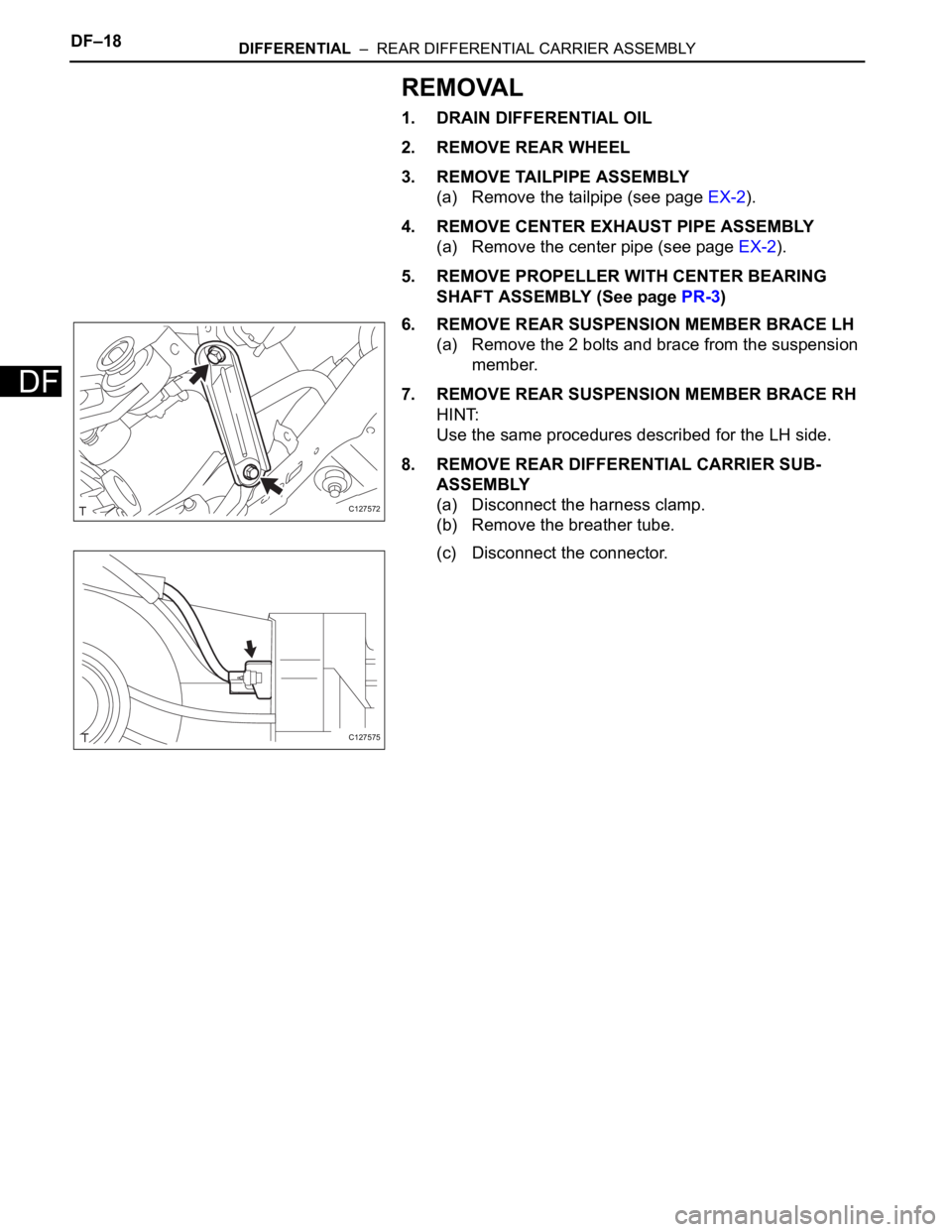
6. REMOVE REAR SUSPENSION MEMBER BRACE LH
(a) Remove the 2 bolts and brace from the suspension
member.
7. REMOVE REAR SUSPENSION MEMBER BRACE RH
HINT:
Use the same procedures described for the LH side.
8. REMOVE REAR DIFFERENTIAL CARRIER SUB-
ASSEMBLY
(a) Disconnect the harness clamp.
(b) Remove the breather tube.
(c) Disconnect the connector.
C127572
C127575
Page 1456 of 2000
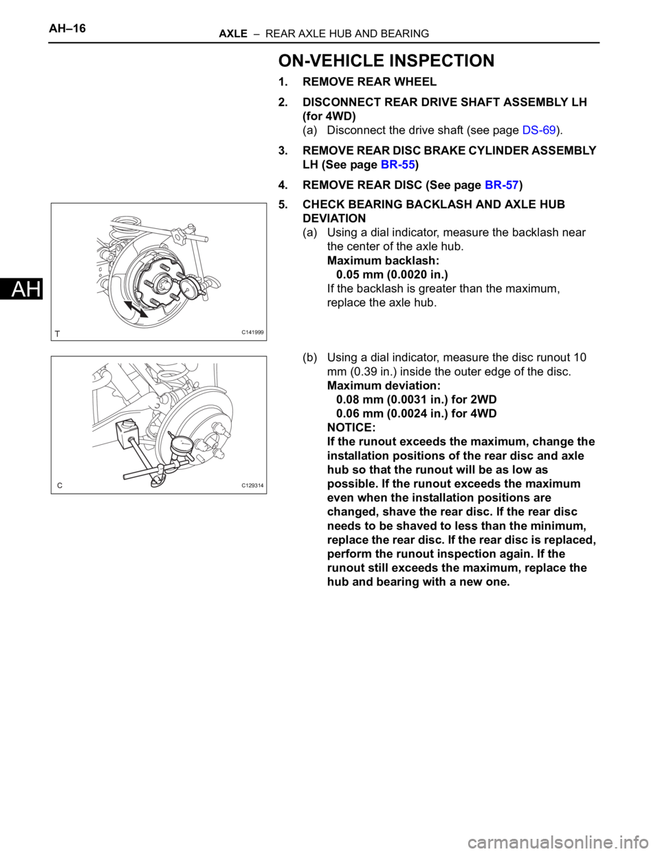
AH–16AXLE – REAR AXLE HUB AND BEARING
AH
ON-VEHICLE INSPECTION
1. REMOVE REAR WHEEL
2. DISCONNECT REAR DRIVE SHAFT ASSEMBLY LH
(for 4WD)
(a) Disconnect the drive shaft (see page DS-69).
3. REMOVE REAR DISC BRAKE CYLINDER ASSEMBLY
LH (See page BR-55)
4. REMOVE REAR DISC (See page BR-57)
5. CHECK BEARING BACKLASH AND AXLE HUB
DEVIATION
(a) Using a dial indicator, measure the backlash near
the center of the axle hub.
Maximum backlash:
0.05 mm (0.0020 in.)
If the backlash is greater than the maximum,
replace the axle hub.
(b) Using a dial indicator, measure the disc runout 10
mm (0.39 in.) inside the outer edge of the disc.
Maximum deviation:
0.08 mm (0.0031 in.) for 2WD
0.06 mm (0.0024 in.) for 4WD
NOTICE:
If the runout exceeds the maximum, change the
installation positions of the rear disc and axle
hub so that the runout will be as low as
possible. If the runout exceeds the maximum
even when the installation positions are
changed, shave the rear disc. If the rear disc
needs to be shaved to less than the minimum,
replace the rear disc. If the rear disc is replaced,
perform the runout inspection again. If the
runout still exceeds the maximum, replace the
hub and bearing with a new one.
C141999
C129314