4WD TOYOTA RAV4 2006 Service Repair Manual
[x] Cancel search | Manufacturer: TOYOTA, Model Year: 2006, Model line: RAV4, Model: TOYOTA RAV4 2006Pages: 2000, PDF Size: 45.84 MB
Page 133 of 2000

CHASSIS - 4WD SYSTEM CH-66
4WD SYSTEM
DESCRIPTION
The 4WD system of the ’06 RAV4 uses an active torque control 4WD system.
It is a compact, lightweight, and high performance 4WD system that optimally controls the torque
distribution to the front and rear wheels through the electric control coupling in the rear differential.
ACTIVE TORQUE CONTROL 4WD SYSTEM
1. General
Based on information provided by various sensors, the 4WD ECU controls the amperage that is applied
to the electric control coupling, in order to transmit drive torque to the rear wheels when needed, and in
the amount needed. The following describes the features of the active torque control 4WD system.
Traction performance
Realizes stable start-off and acceleration performance
Driving stability performanceRealizes stable cornering performance
Fuel economyRealizes better fuel economy by transmitting drive torque to the rear
wheels when needed, in the amount needed.
A four-wheel drive lock switch has been provided. This enables the driver to select between the AUTO
and LOCK modes by operating the switch. The system optimally controls the torque distribution to the
front and rear wheels in the respective modes.
Mode
Four-wheel Drive
Lock Switch and
Indicator Light
Outline
AUTOOFF
Optimally distributes drive torque to the front and rear wheels.
Ensures optimal start-off performance during a start-off, based on
information provided by various sensors.
Suppresses the tight corner braking phenomenon* during low-speed
cornering.
Reduces the amount of torque distribution to the rear wheels and
improves fuel economy when the system judges that the vehicle is
traveling steadily.
Disengages the 4WD during braking deceleration.
LOCKON
Distributes the maximum torque limit to the rear wheels.
Distributes the maximum torque limit to the rear wheels during
start-off.
Distributes optimal torque during low-speed cornering.
Disengages the 4WD during braking deceleration.
Disengages the LOCK mode and transfers to the AUTO mode when
the vehicle speed exceeds 40 km / h (25 mph).
*: Tight corner braking phenomenon: a condition in which the brakes are applied due to a rotational difference
between the front and rear wheels, such as during low-speed cornering in the 4WD mode.
The 4WD ECU effects cooperative control with the skid control ECU, in order to control the drive torque
distribution to the front and rear wheels in accordance with information received from the skid control
ECU. These controls ensure a smooth acceleration and driving stability.
Page 134 of 2000

CHASSIS - 4WD SYSTEM
01MCH09Y
Electric Control Coupling
4WD ECU
Four-wheel Drive
Lock Switch
4WD LOCK
Indicator Light
4WD Warning
LightECM
Skid Control ECU
Main Body ECU
Ya w R a t e &
Deceleration Sensor
Steering Angle
SensorThrottle Position Sensor
Crankshaft Position Sensor
Park / Neutral Position
Switch
Speed Sensors
Stop Light Switch
Ambient Temperature
Sensor
Parking Brake Switch
CANH,
CANLCH-67
2. System Diagram
Page 135 of 2000

CHASSIS - 4WD SYSTEM
01NCH36Y
Skid Control ECU
Electric Control Coupling
ECM Ambient Temperature
Sensor
Main Body ECUSteering Angle
Sensor
Four-wheel Drive
Lock Switch
4WD ECU
Parking Brake
Switch Stop Light Switch
Yaw Rate & Deceleration
Sensor DLC3 CH-68
3. Layout of Main Components
Page 136 of 2000

CHASSIS - 4WD SYSTEMCH-69
4. Function of Main Components
ComponentFunction
Combination
4WD LOCK
Indicator LightIlluminates to inform the driver of the 4WD LOCK mode control.Combination
Meter4WD
Warning LightIlluminates to warn the driver of a malfunction in the 4WD system.
Speed Sensor (4)Detects the wheel speed of each 4 wheel.
Steering Angle SensorDetects the direction and angle of the steering wheel.
Yaw Rate & Deceleration SensorDetects the vehicle’s longitudinal and lateral acceleration.
Crankshaft Position SensorDetects the engine speed and outputs it to the ECM.
Accelerator Pedal Position SensorDetects the accelerator pedal position and outputs it to the ECM.
Throttle Position SensorDetects the throttle valve position and outputs it to the ECM.
Park / Neutral Position SwitchDetects the neutral position of the transaxle and outputs it to the
ECM.
Stop Light SwitchDetects the brake pedal depressing signal.
Parking Brake SwitchDetects when the parking brake lever is pulled up.
Four-wheel Drive Lock SwitchSwitches between the AUTO and LOCK modes.
4WD ECU
Controls the amperage that is applied to the electromagnetic
solenoid of the electric control coupling based on the signals
provided by the sensors in order to optimally distribute drive torque
in accordance with driving conditions.
ECMOutputs signals such as the shift position signal, throttle position
signal, and crankshaft position signal to the 4WD ECU.
Skid Control ECUOutputs signals such as the vehicle speed signal and deceleration
signal to the 4WD ECU.
Electric Control CouplingDistributes drive torque in accordance with the amperage applied
by the 4WD ECU.
Page 137 of 2000

CHASSIS - 4WD SYSTEM
01NCH38Y
Torque Distribution
to Rear WheelsTorque Distribution
to Rear Wheels
Straightline Driving Low-Speed Cornering
01NCH39Y
Torque Distribution
to Rear WheelsTorque Distribution
to Rear Wheels
Steady Driving Straightline Acceleration
NOTICE
In the LOCK mode after the four-wheel drive lock switch is pressed, the system starts control upon
judging that the vehicle is operating in a stable manner. During this judgment, the 4WD LOCK
indicator light blinks.
CH-70
5. System Operation
Auto Mode
1) Starting Off
The system ensures start-off performance by optimally distributing the entire drive torque, which is
transmitted by the engine, to the front and rear wheels.
To prevent the tight corner braking phenomenon from occurring during low-speed cornering, the
system reduces the amount of torque distribution to the rear wheels.
2) Normal Driving
During normal driving, when the system judges that the vehicle is traveling steadily, it reduces the
amount of torque distribution to the rear wheels. This allows the vehicle to operate in conditions
similar to front-wheel-drive, which improves fuel economy.
To ensure excellent acceleration performance during straightline acceleration and excellent driving
stability during cornering, the system controls the amount of torque distribution to the rear wheels.
Lock Mode
When the vehicle is in a situation that poses difficulty for it to pull itself out, such as sand, the driver can
switch to LOCK mode by operating the four-wheel drive lock switch. Thus, this mode effects optimal
control in accordance with the driving conditions and transmits as much drive torque as possible to the rear
wheels, in a mode that is similar to the locked 4WD mode.
Page 138 of 2000

CHASSIS - 4WD SYSTEM
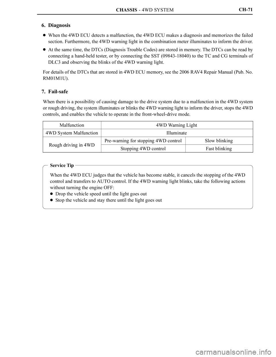
Service Tip
When the 4WD ECU judges that the vehicle has become stable, it cancels the stopping of the 4WD
control and transfers to AUTO control. If the 4WD warning light blinks, take the following actions
without turning the engine OFF:
Drop the vehicle speed until the light goes out
Stop the vehicle and stay there until the light goes out
CH-71
6. Diagnosis
When the 4WD ECU detects a malfunction, the 4WD ECU makes a diagnosis and memorizes the failed
section. Furthermore, the 4WD warning light in the combination meter illuminates to inform the driver.
At the same time, the DTCs (Diagnosis Trouble Codes) are stored in memory. The DTCs can be read by
connecting a hand-held tester, or by connecting the SST (09843-18040) to the TC and CG terminals of
DLC3 and observing the blinks of the 4WD warning light.
For details of the DTCs that are stored in 4WD ECU memory, see the 2006 RAV4 Repair Manual (Pub. No.
RM01M1U).
7. Fail-safe
When there is a possibility of causing damage to the drive system due to a malfunction in the 4WD system
or rough driving, the system illuminates or blinks the 4WD warning light to inform the driver, stops the 4WD
controls, and enables the vehicle to operate in the front-wheel-drive mode.
Malfunction
4WD Warning Light
4WD System MalfunctionIlluminate
Rough driving in 4WDPre-warning for stopping 4WD controlSlow blinkingRough driving in 4WDStopping 4WD controlFast blinking
Page 194 of 2000

2GR-FE ENGINE CONTROL SYSTEM – ECMES–471
ES
INSTALLATION
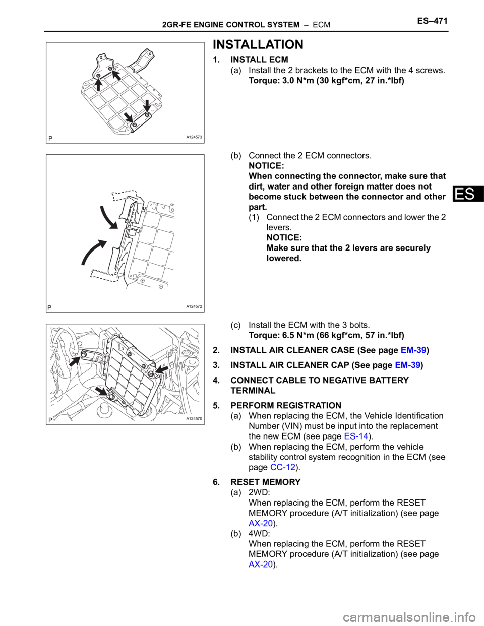
1. INSTALL ECM
(a) Install the 2 brackets to the ECM with the 4 screws.
Torque: 3.0 N*m (30 kgf*cm, 27 in.*lbf)
(b) Connect the 2 ECM connectors.
NOTICE:
When connecting the connector, make sure that
dirt, water and other foreign matter does not
become stuck between the connector and other
part.
(1) Connect the 2 ECM connectors and lower the 2
levers.
NOTICE:
Make sure that the 2 levers are securely
lowered.
(c) Install the ECM with the 3 bolts.
Torque: 6.5 N*m (66 kgf*cm, 57 in.*lbf)
2. INSTALL AIR CLEANER CASE (See page EM-39)
3. INSTALL AIR CLEANER CAP (See page EM-39)
4. CONNECT CABLE TO NEGATIVE BATTERY
TERMINAL
5. PERFORM REGISTRATION
(a) When replacing the ECM, the Vehicle Identification
Number (VIN) must be input into the replacement
the new ECM (see page ES-14).
(b) When replacing the ECM, perform the vehicle
stability control system recognition in the ECM (see
page CC-12).
6. RESET MEMORY
(a) 2WD:
When replacing the ECM, perform the RESET
MEMORY procedure (A/T initialization) (see page
AX-20).
(b) 4WD:
When replacing the ECM, perform the RESET
MEMORY procedure (A/T initialization) (see page
AX-20).
A124573
A124572
A124570
Page 196 of 2000

2GR-FE ENGINE MECHANICAL – ENGINE ASSEMBLYEM–21
EM
REMOVAL
1. DISCHARGE REFRIGERANT FROM
REFRIGERATION SYSTEM (See page AC-172)
2. DISCHARGE FUEL SYSTEM PRESSURE (See page
FU-13)
3. DISCONNECT CABLE FROM NEGATIVE BATTERY
TERMINAL
CAUTION:
Wait at least 90 seconds after disconnecting the
cable from the negative (-) battery terminal to
prevent airbag and seat belt pretensioner activation.
4. REMOVE NO. 1 ENGINE UNDER COVER
(a) Remove the 4 bolts, 12 clips and under cover.
5. REMOVE REAR ENGINE UNDER COVER RH
(a) Remove the 2 clips and under cover.
6. REMOVE REAR ENGINE UNDER COVER LH
(a) Remove the 2 clips and under cover.
7. REMOVE NO. 2 ENGINE UNDER COVER
(a) Remove the 2 clips and under cover.
8. REMOVE FRONT FLOOR COVER (See page FU-34)
9. DRAIN ENGINE COOLANT (See page CO-8)
10. DRAIN ENGINE OIL (See page LU-4)
11. DRAIN AUTOMATIC TRANSAXLE FLUID
(a) 2WD:
Drain automatic transaxle fluid (see page AX-172).
(b) 4WD:
Drain automatic transaxle fluid (see page AX-173)
12. DRAIN TRANSFER OIL (for 4WD)
13. REMOVE HOOD SUB-ASSEMBLY (See page ED-4)
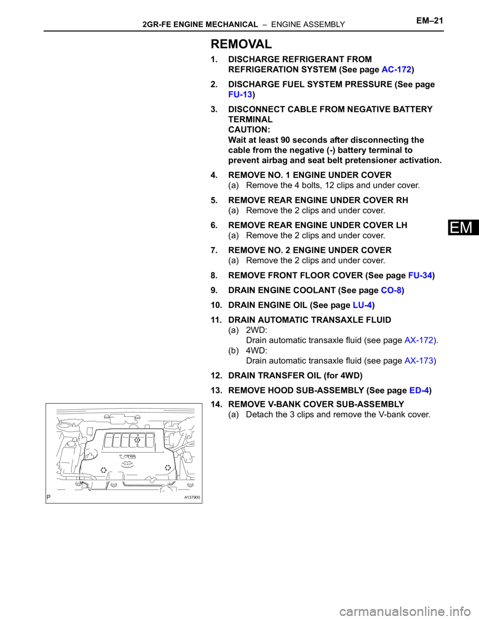
14. REMOVE V-BANK COVER SUB-ASSEMBLY
(a) Detach the 3 clips and remove the V-bank cover.
A137900
Page 199 of 2000

EM–242GR-FE ENGINE MECHANICAL – ENGINE ASSEMBLY
EM
(b) 4WD:
Disconnect the control cable (see page AX-154).
31. REMOVE FRONT EXHAUST PIPE ASSEMBLY (See
page EX-3)
32. REMOVE CENTER EXHAUST PIPE ASSEMBLY (See
page EX-2)
33. REMOVE PROPELLER WITH CENTER BEARING
SHAFT ASSEMBLY (See page PR-3)
34. REMOVE FRONT WHEELS
35. REMOVE FRONT AXLE HUB NUT LH
(a) Remove the hub nut (see page AH-8).
36. REMOVE FRONT AXLE HUB NUT RH
(a) Remove the hub nut (see page AH-8).
37. DISCONNECT FRONT STABILIZER LINK ASSEMBLY
LH (See page SP-30)
38. DISCONNECT FRONT STABILIZER LINK ASSEMBLY
RH (See page SP-30)
39. DISCONNECT STEERING INTERMEDIATE SHAFT
(See page PS-44)
40. DISCONNECT TIE ROD END SUB-ASSEMBLY RH
(See page PS-42)
41. DISCONNECT TIE ROD END SUB-ASSEMBLY LH
(See page PS-42)
42. REMOVE FRONT DRIVE SHAFT LH
(a) 2WD:
Remove the drive shaft (see page DS-10).
(b) 4WD:
Remove the drive shaft (see page DS-43).
43. REMOVE FRONT DRIVE SHAFT RH
(a) 2WD:
Remove the drive shaft (see page DS-10).
(b) 4WD:
Remove the drive shaft (see page DS-43).
44. REMOVE ENGINE WITH TRANSAXLE
(a) Install the No. 1 and No. 2 engine hangers with the
4 bolts as shown in the illustration.
Torque: 33 N*m (337 kgf*cm, 24 ft.*lbf)
HINT:
• Insert the claw of the hanger into hole of the
cylinder head.
• Fit the fork part of the hanger onto the rib of the
cylinder head.
A129635E02
Part Name Part No.
No. 1 engine hanger 12281-31120
No. 2 engine hanger 12282-31100
Bolt 91671-10825
Page 201 of 2000

EM–262GR-FE ENGINE MECHANICAL – ENGINE ASSEMBLY
EM
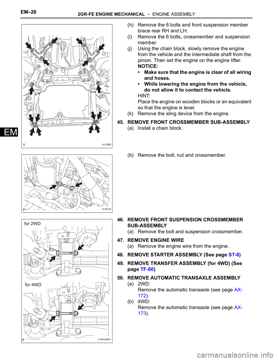
(h) Remove the 6 bolts and front suspension member
brace rear RH and LH.
(i) Remove the 6 bolts, crossmember and suspension
member.
(j) Using the chain block, slowly remove the engine
from the vehicle and the intermediate shaft from the
pinion. Then set the engine on the engine lifter.
NOTICE:
• Make sure that the engine is clear of all wiring
and hoses.
• While lowering the engine from the vehicle,
do not allow it to contact the vehicle.
HINT:
Place the engine on wooden blocks or an equivalent
so that the engine is level.
(k) Remove the sling device from the engine.
45. REMOVE FRONT CROSSMEMBER SUB-ASSEMBLY
(a) Install a chain block.
(b) Remove the bolt, nut and crossmember.
46. REMOVE FRONT SUSPENSION CROSSMEMBER
SUB-ASSEMBLY
(a) Remove the bolt and suspension crossmember.
47. REMOVE ENGINE WIRE
(a) Remove the engine wire from the engine.
48. REMOVE STARTER ASSEMBLY (See page ST-6)
49. REMOVE TRANSFER ASSEMBLY (for 4WD) (See
page TF-60)
50. REMOVE AUTOMATIC TRANSAXLE ASSEMBLY
(a) 2WD:
Remove the automatic transaxle (see page AX-
172).
(b) 4WD:
Remove the automatic transaxle (see page AX-
173).
A123580
A139135
A139136E01