ad blue TOYOTA RAV4 2006 Service Repair Manual
[x] Cancel search | Manufacturer: TOYOTA, Model Year: 2006, Model line: RAV4, Model: TOYOTA RAV4 2006Pages: 2000, PDF Size: 45.84 MB
Page 610 of 2000
EM–662AZ-FE ENGINE MECHANICAL – CYLINDER HEAD
EM
INSPECTION
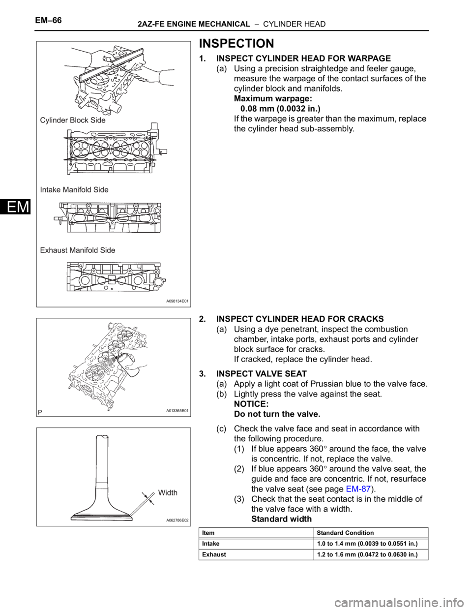
1. INSPECT CYLINDER HEAD FOR WARPAGE
(a) Using a precision straightedge and feeler gauge,
measure the warpage of the contact surfaces of the
cylinder block and manifolds.
Maximum warpage:
0.08 mm (0.0032 in.)
If the warpage is greater than the maximum, replace
the cylinder head sub-assembly.
2. INSPECT CYLINDER HEAD FOR CRACKS
(a) Using a dye penetrant, inspect the combustion
chamber, intake ports, exhaust ports and cylinder
block surface for cracks.
If cracked, replace the cylinder head.
3. INSPECT VALVE SEAT
(a) Apply a light coat of Prussian blue to the valve face.
(b) Lightly press the valve against the seat.
NOTICE:
Do not turn the valve.
(c) Check the valve face and seat in accordance with
the following procedure.
(1) If blue appears 360
around the face, the valve
is concentric. If not, replace the valve.
(2) If blue appears 360
around the valve seat, the
guide and face are concentric. If not, resurface
the valve seat (see page EM-87).
(3) Check that the seat contact is in the middle of
the valve face with a width.
Standard width
A098134E01
A013365E01
A062786E02
Item Standard Condition
Intake 1.0 to 1.4 mm (0.0039 to 0.0551 in.)
Exhaust 1.2 to 1.6 mm (0.0472 to 0.0630 in.)
Page 724 of 2000

2GR-FE ENGINE MECHANICAL – ENGINE UNITEM–87
EM
20. INSPECT INTAKE VALVE SEAT
(a) Apply a light coat of Prussian blue to the valve face.
(b) Lightly press the valve face against the valve seat.
(c) Check the valve face and valve seat by using the
following procedure.
(1) If Prussian blue appears around the entire
valve face, the valve face is concentric. If not,
replace the valve.
(2) If Prussian blue appears around the entire
valve seat, the guide and valve face are
concentric. If not, resurface the valve seat.
(3) Check that the valve seat contacts in the
middle of the valve face with the width between
1.1 and 1.5 mm (0.043 and 0.059 in.).
21. INSPECT EXHAUST VALVE SEAT
(a) Apply a light coat of Prussian blue to the valve face.
(b) Lightly press the valve face against the valve seat.
(c) Check the valve face and valve seat by using the
following procedure.
(1) If Prussian blue appears around the entire
valve face, the valve face is concentric. If not,
replace the valve.
(2) If Prussian blue appears around the entire
valve seat, the guide and valve face are
concentric. If not, resurface the valve seat.
(3) Check that the valve seat contacts in the
middle of the valve face with the width between
1.2 and 1.6 mm (0.047 and 0.063 in.).
22. INSPECT INNER COMPRESSION SPRING
(a) Using a vernier caliper, measure the free length of
the inner compression spring.
Standard free length:
45.46 mm (1.7898 in.)
If the free length is not as specified, replace the
spring.
(b) Using a steel square, measure the deviation of the
inner compression spring.
Maximum deviation:
1.0 mm (0.039 in.)
Maximum angle (reference):
2
If the deviation is greater than the maximum,
replace the spring.
A132152E01
A132152E01
A101392
A101393E02
Page 1003 of 2000

U140F AUTOMATIC TRANSAXLE – AUTOMATIC TRANSAXLE UNITAX–209
AX
49. INSTALL MANUAL DETENT SPRING SUB-
ASSEMBLY
(a) Install the manual detent spring with the 2 bolts.
NOTICE:
Make sure to install the manual detent spring
and cover in this order.
Torque: 20 N*m (204 kgf*cm, 16 ft.*lbf) for bolt A
12 N*m (122 kgf*cm, 9 ft.*lbf) for bolt B
HINT:
Each bolt length is indicated below.
27 mm (1.063 in.) for bolt A
16 mm (0.630 in.) for bolt B
50. INSTALL B-3 ACCUMULATOR PISTON
(a) Coat a new O-ring with ATF, and install it to the B-3
accumulator piston.
(b) Coat the piston with ATF, install it to the transaxle.
Standard accumulator spring
51. INSTALL C-1 ACCUMULATOR PISTON
(a) Coat 2 new O-rings with ATF, and install them to the
C-1 accumulator piston.
D003560E01
D003904E05
D025512E02
Spring Free length
Outer diameterColor
B-3 Inner 60.24 mm (2.3716 in.)
15.9 (0.626 in.)Yellowish green
B-3 Outer 74.61 mm (2.9374 in.)
21.7 mm (0.854 in.)Blue
D003903E01
Page 1106 of 2000
AX–232U151E AUTOMATIC TRANSAXLE – AUTOMATIC TRANSAXLE UNIT
AX
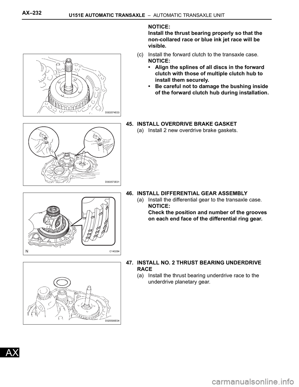
NOTICE:
Install the thrust bearing properly so that the
non-collared race or blue ink jet race will be
visible.
(c) Install the forward clutch to the transaxle case.
NOTICE:
• Align the splines of all discs in the forward
clutch with those of multiple clutch hub to
install them securely.
• Be careful not to damage the bushing inside
of the forward clutch hub during installation.
45. INSTALL OVERDRIVE BRAKE GASKET
(a) Install 2 new overdrive brake gaskets.
46. INSTALL DIFFERENTIAL GEAR ASSEMBLY
(a) Install the differential gear to the transaxle case.
NOTICE:
Check the position and number of the grooves
on each end face of the differential ring gear.
47. INSTALL NO. 2 THRUST BEARING UNDERDRIVE
RACE
(a) Install the thrust bearing underdrive race to the
underdrive planetary gear.
D003574E03
D003573E01
C140284
D025506E04
Page 1211 of 2000
U151F AUTOMATIC TRANSAXLE – AUTOMATIC TRANSAXLE UNITAX–233
AX
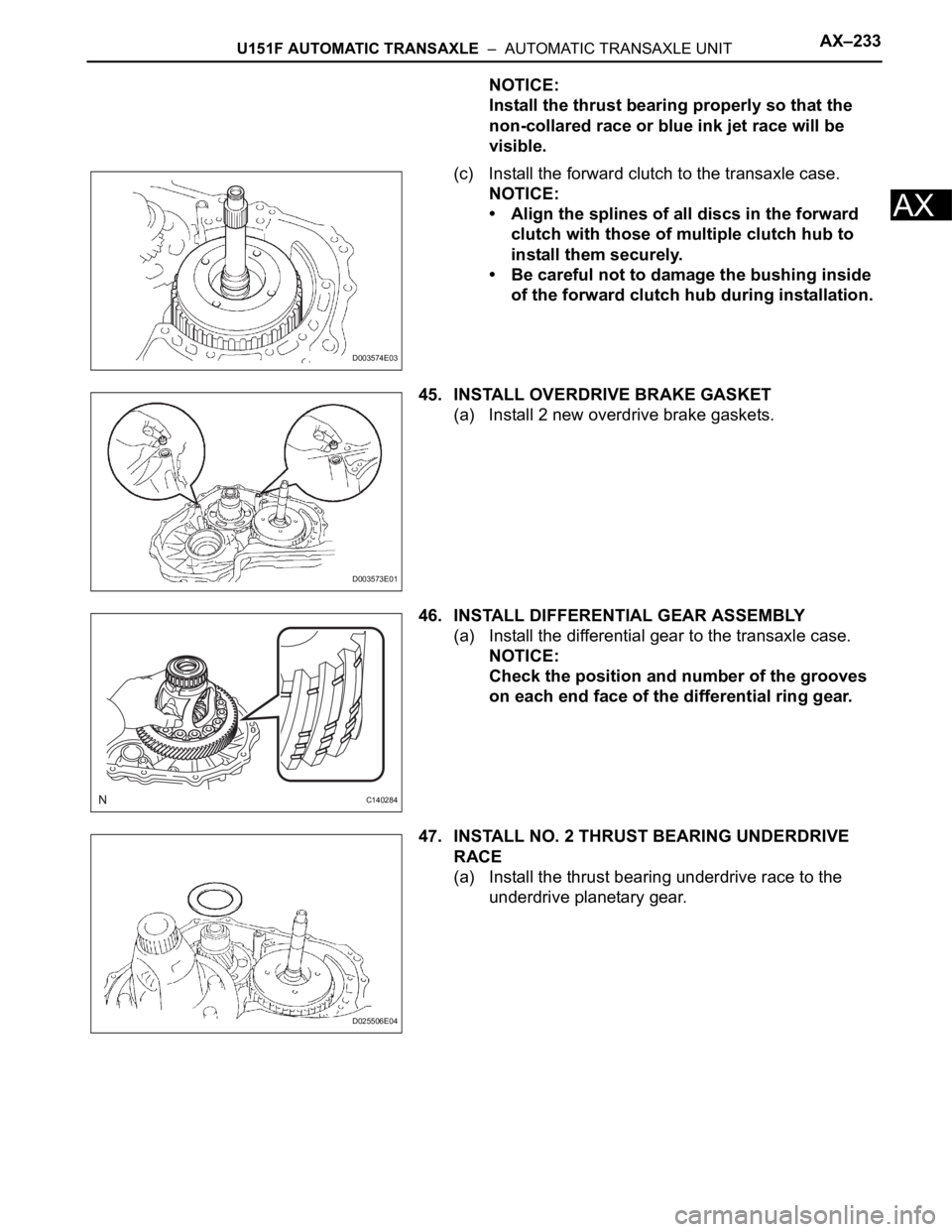
NOTICE:
Install the thrust bearing properly so that the
non-collared race or blue ink jet race will be
visible.
(c) Install the forward clutch to the transaxle case.
NOTICE:
• Align the splines of all discs in the forward
clutch with those of multiple clutch hub to
install them securely.
• Be careful not to damage the bushing inside
of the forward clutch hub during installation.
45. INSTALL OVERDRIVE BRAKE GASKET
(a) Install 2 new overdrive brake gaskets.
46. INSTALL DIFFERENTIAL GEAR ASSEMBLY
(a) Install the differential gear to the transaxle case.
NOTICE:
Check the position and number of the grooves
on each end face of the differential ring gear.
47. INSTALL NO. 2 THRUST BEARING UNDERDRIVE
RACE
(a) Install the thrust bearing underdrive race to the
underdrive planetary gear.
D003574E03
D003573E01
C140284
D025506E04
Page 1315 of 2000
U241E AUTOMATIC TRANSAXLE – AUTOMATIC TRANSAXLE UNITAX–211
AX
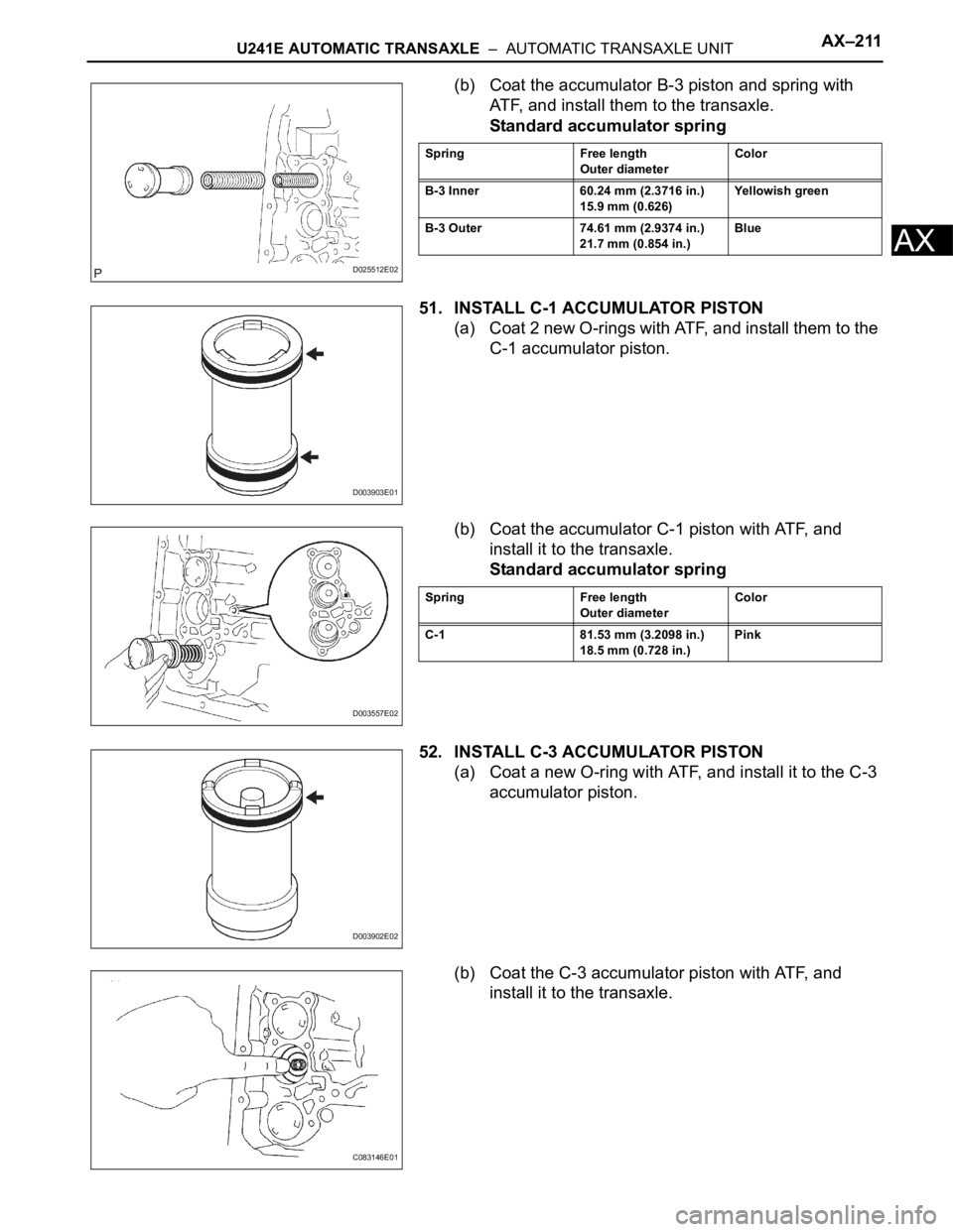
(b) Coat the accumulator B-3 piston and spring with
ATF, and install them to the transaxle.
Standard accumulator spring
51. INSTALL C-1 ACCUMULATOR PISTON
(a) Coat 2 new O-rings with ATF, and install them to the
C-1 accumulator piston.
(b) Coat the accumulator C-1 piston with ATF, and
install it to the transaxle.
Standard accumulator spring
52. INSTALL C-3 ACCUMULATOR PISTON
(a) Coat a new O-ring with ATF, and install it to the C-3
accumulator piston.
(b) Coat the C-3 accumulator piston with ATF, and
install it to the transaxle.
D025512E02
Spring Free length
Outer diameterColor
B-3 Inner 60.24 mm (2.3716 in.)
15.9 mm (0.626)Yellowish green
B-3 Outer 74.61 mm (2.9374 in.)
21.7 mm (0.854 in.)Blue
D003903E01
D003557E02
Spring Free length
Outer diameterColor
C-1 81.53 mm (3.2098 in.)
18.5 mm (0.728 in.)Pink
D003902E02
C083146E01
Page 1438 of 2000
DF–34DIFFERENTIAL – REAR DIFFERENTIAL CARRIER ASSEMBLY
DF
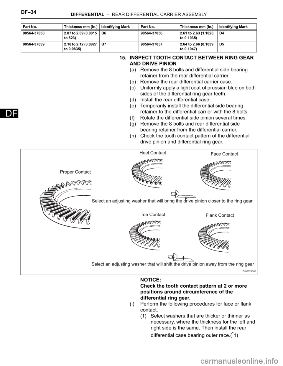
15. INSPECT TOOTH CONTACT BETWEEN RING GEAR
AND DRIVE PINION
(a) Remove the 8 bolts and differential side bearing
retainer from the rear differential carrier.
(b) Remove the rear differential carrier case.
(c) Uniformly apply a light coat of prussian blue on both
sides of the differential ring gear teeth.
(d) Install the rear differential case.
(e) Temporarily install the differential side bearing
retainer to the differential carrier with the 8 bolts.
(f) Rotate the differential side pinion several times.
(g) Remove the 8 bolts and rear differential side
bearing retainer from the differential carrier.
(h) Check the tooth contact pattern of the differential
drive pinion and differential ring gear.
NOTICE:
Check the tooth contact pattern at 2 or more
positions around circumference of the
differential ring gear.
(i) Perform the following procedures for face or flank
contact.
(1) Select washers that are thicker or thinner as
necessary, where the thickness for the left and
right side is the same. Then install the rear
differential case bearing outer race.(
*1)
90564-37038 2.07 to 2.09 (0.0815
to 823)B6 90564-37056 2.61 to 2.63 (1.1028
to 0.1035)D4
90564-37039 2.10 to 2.12 (0.0827
to 0.0835)B7 90564-37057 2.64 to 2.66 (0.1039
to 0.1047)D5 Part No. Thickness mm (in.) Identifying Mark Part No. Thickness mm (in.) Identifying Mark
ZK03673E02