compression ratio TOYOTA RAV4 2006 Service Repair Manual
[x] Cancel search | Manufacturer: TOYOTA, Model Year: 2006, Model line: RAV4, Model: TOYOTA RAV4 2006Pages: 2000, PDF Size: 45.84 MB
Page 66 of 2000

ENGINE - 2AZ-FE ENGINE
01MEG02Y
Valve Timing : Intake Valve Opening Angle
: Exhaust Valve Opening Angle
VVT-i Operation
Range
VVT-i Operation
RangeTDC
3
3
43
65
25
45
BDCEG-3
Engine Specifications
No. of Cyls. & Arrangement4-cylinder, In-line
Valve Mechanism16-valve DOHC, Chain Drive (with VVT-i)
Combustion ChamberPentroof Type
ManifoldsCross-flow
Fuel SystemSFI
Ignition SystemDIS
Displacement cm3 (cu. in.)2362 (144.1)
Bore x Stroke mm (in.)88.5 x 96.0 (3.48 x 3.78)
Compression Ratio9.8 : 1
Max. Output*1(SAE-NET)124 kW @ 6000 rpm (166 HP @ 6000 rpm)
Max. Torque*1(SAE-NET)224 N.m @ 4000 rpm (165 ft-lbf @ 4000 rpm)
IntakeOpen3 - 43 BTDC
Valve Timing
IntakeClose65 - 25 ABDCVa l v e T i m i n g
ExhaustOpen45 BBDCExhaustClose3 ATDC
Firing Order1 - 3 - 4 - 2
Research Octane Number91 or higher
Octane Rating87 or higher
Oil GradeILSAC
Tailpipe Emission RegulationULEV-II, SFTP
Evaporative Emission RegulationLEV-II, ORVR
Engine Service Mass*2 (Reference) kg (lb)138 (304.2)
*1: Maximum output and torque rating is determined by revised SAE J1349 standard.
*
2: Weight shows the figure with oil and water fully filled.
Page 131 of 2000

ENGINE - 2GR-FE ENGINEEG-69
Engine Specifications
No. of Cyls. & Arrangement6-cylinder, V Type
Valve Mechanism24-valve DOHC, Chain Drive (with Dual VVT-i)
Combustion ChamberPentroof-type
ManifoldsParallel-flow
Fuel SystemSFI
Ignition SystemDIS
Displacement cm3
(cu. in.)3456 (210.9)
Bore x Stroke mm (in.)94.0 x 83.0 (3.70 x 3.27)
Compression Ratio10.8 : 1
Max. Output (SAE-NET)*1201 kW @ 6200 rpm (269 HP @ 6200 rpm)
Max. Torque (SAE-NET)*1333 N.m @ 4700 rpm (247 ft.lbf @ 4700 rpm)
Intake ValveOpen-3 to 37 BTDC
Valve Timing
Intake ValveClose71 to 31 ABDCVa l v e T i m i n g
Exhaust ValveOpen60 to 25 BBDCExhaust ValveClose4 to 39 ATDC
Firing Order1 - 2 - 3 - 4 - 5 - 6
Octane Rating91 or higher
Engine Oil GradeILSAC multigrade engine oil
CaliforniaULEVII, SFTP
EmissionTailpipeExceptTier2 Bin5 SFTPEmission
Regulation
ppExcept
CaliforniaTier2-Bin5, SFTPg
EvaporativeLEVII, ORVR
Engine Service Mass*2 (Reference) kg (lb)163 (359)
*1: Maximum output and torque rating is determined by revised SAE J1349 standard.
*
2: Weight shows the figure with the oil and engine coolant fully filled.
Page 257 of 2000

PP–10PREPARATION – 2GR-FE ENGINE MECHANICAL
PP
EQUIPMENT
Alignment tester -
Angle gauge -
Brass bar -
Caliper gauge -
Chain block -
Compression gauge -
CO/HC meter -
Connecting rod aligner -
Cylinder gauge -
Dial indicator with magnetic base -
Engine stand -
Feeler gauge -
Gasket scraper -
Magnetic finger -
Micrometer -
Needle-nose pliers -
No. 1 engine hanger -
No. 2 engine hanger -
Pin hole grinder -
Piston ring compressor -
Piston ring expander -
Piston heater -
Plastigage -
Plastic-faced hammer -
Press -
Radiator cap tester -
Reamer (5.5 mm) -
Ridge reamer -
Rod aligner -
Sandpaper (#400) -
Slide calipers -
Straightedge -
Spring scale -
Spring tension gauge -
Steel square -
Tachometer -
Timing light -
Toe-in gauge -
To r q u e w r e n c h -
Valve seat cutter -
V-block -
Vernier calipers -
Vise -
Wooden block -
Page 484 of 2000
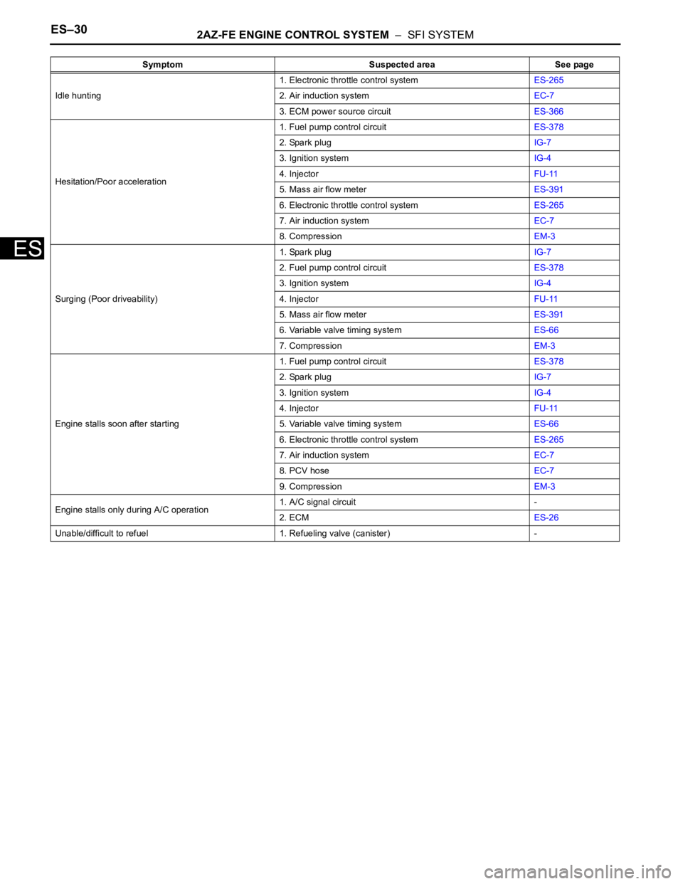
ES–302AZ-FE ENGINE CONTROL SYSTEM – SFI SYSTEM
ES
Idle hunting1. Electronic throttle control systemES-265
2. Air induction systemEC-7
3. ECM power source circuitES-366
Hesitation/Poor acceleration1. Fuel pump control circuitES-378
2. Spark plugIG-7
3. Ignition systemIG-4
4. InjectorFU-11
5. Mass air flow meterES-391
6. Electronic throttle control systemES-265
7. Air induction systemEC-7
8. CompressionEM-3
Surging (Poor driveability)1. Spark plugIG-7
2. Fuel pump control circuitES-378
3. Ignition systemIG-4
4. InjectorFU-11
5. Mass air flow meterES-391
6. Variable valve timing systemES-66
7. CompressionEM-3
Engine stalls soon after starting1. Fuel pump control circuitES-378
2. Spark plugIG-7
3. Ignition systemIG-4
4. InjectorFU-11
5. Variable valve timing systemES-66
6. Electronic throttle control systemES-265
7. Air induction systemEC-7
8. PCV hoseEC-7
9. CompressionEM-3
Engine stalls only during A/C operation1. A/C signal circuit -
2. ECMES-26
Unable/difficult to refuel 1. Refueling valve (canister) - Symptom Suspected area See page
Page 557 of 2000
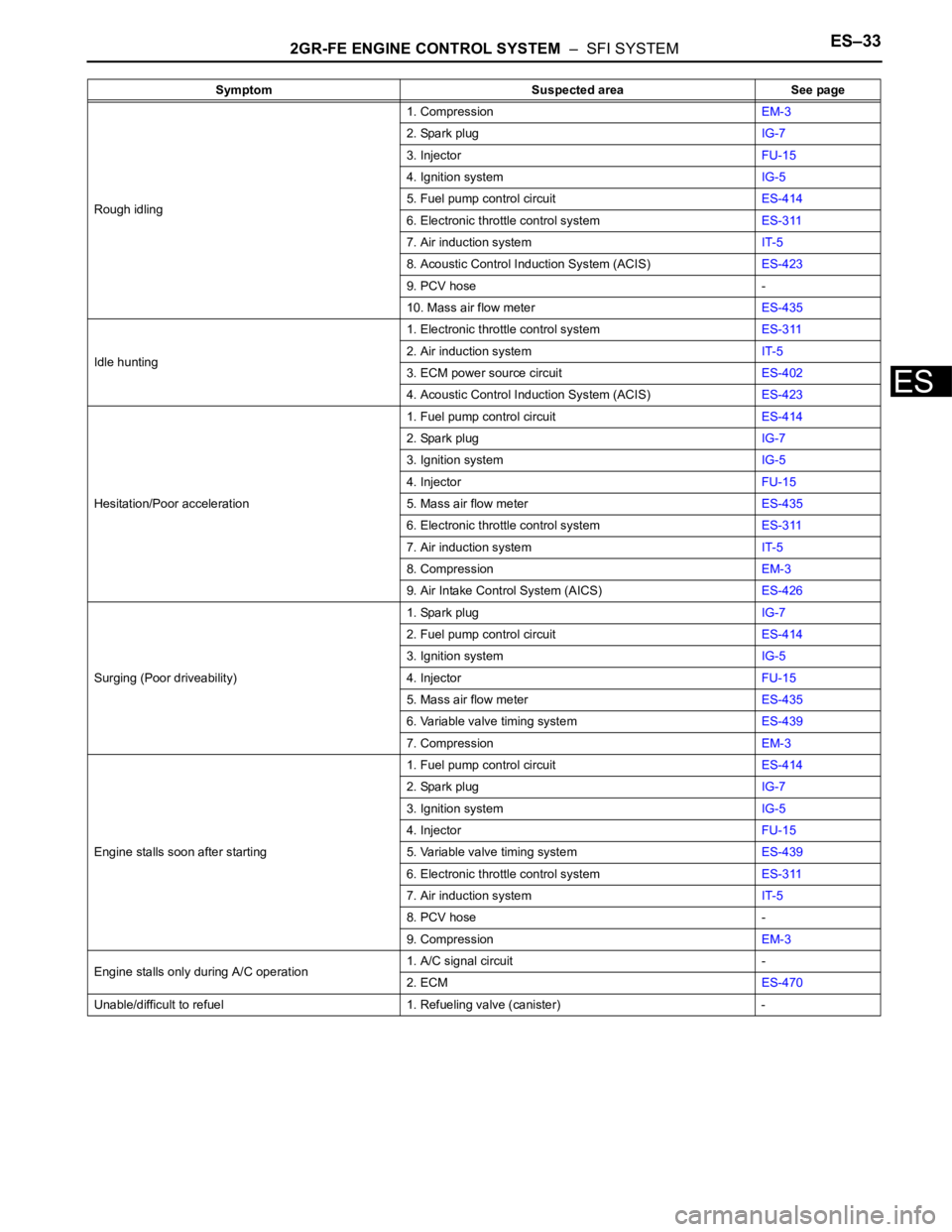
2GR-FE ENGINE CONTROL SYSTEM – SFI SYSTEMES–33
ES
Rough idling1. CompressionEM-3
2. Spark plugIG-7
3. InjectorFU-15
4. Ignition systemIG-5
5. Fuel pump control circuitES-414
6. Electronic throttle control systemES-311
7. Air induction systemIT-5
8. Acoustic Control Induction System (ACIS)ES-423
9. PCV hose -
10. Mass air flow meterES-435
Idle hunting1. Electronic throttle control systemES-311
2. Air induction systemIT-5
3. ECM power source circuitES-402
4. Acoustic Control Induction System (ACIS)ES-423
Hesitation/Poor acceleration1. Fuel pump control circuitES-414
2. Spark plugIG-7
3. Ignition systemIG-5
4. InjectorFU-15
5. Mass air flow meterES-435
6. Electronic throttle control systemES-311
7. Air induction systemIT-5
8. CompressionEM-3
9. Air Intake Control System (AICS)ES-426
Surging (Poor driveability)1. Spark plugIG-7
2. Fuel pump control circuitES-414
3. Ignition systemIG-5
4. InjectorFU-15
5. Mass air flow meterES-435
6. Variable valve timing systemES-439
7. CompressionEM-3
Engine stalls soon after starting1. Fuel pump control circuitES-414
2. Spark plugIG-7
3. Ignition systemIG-5
4. InjectorFU-15
5. Variable valve timing systemES-439
6. Electronic throttle control systemES-311
7. Air induction systemIT-5
8. PCV hose -
9. CompressionEM-3
Engine stalls only during A/C operation1. A/C signal circuit -
2. ECMES-470
Unable/difficult to refuel 1. Refueling valve (canister) -Symptom Suspected area See page
Page 582 of 2000
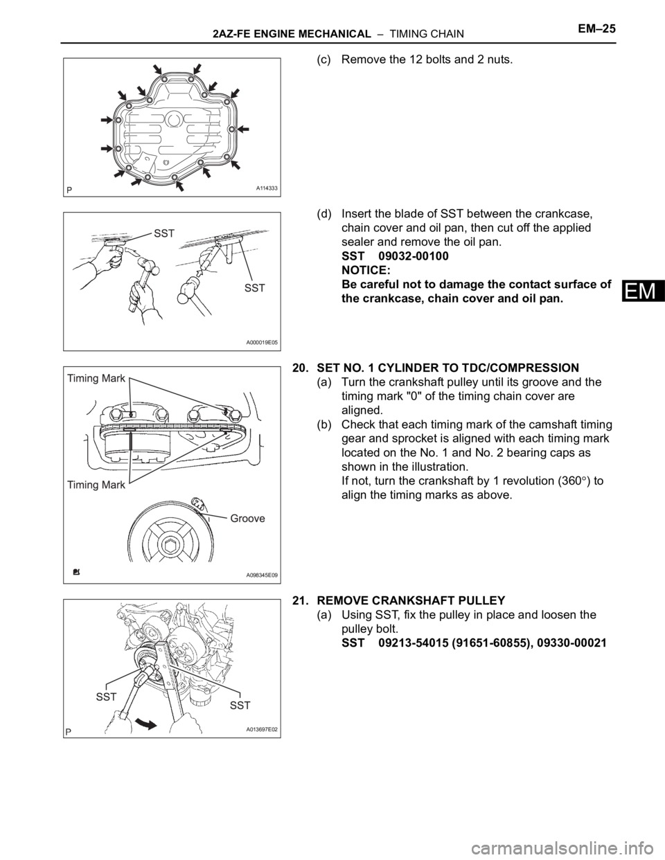
2AZ-FE ENGINE MECHANICAL – TIMING CHAINEM–25
EM
(c) Remove the 12 bolts and 2 nuts.
(d) Insert the blade of SST between the crankcase,
chain cover and oil pan, then cut off the applied
sealer and remove the oil pan.
SST 09032-00100
NOTICE:
Be careful not to damage the contact surface of
the crankcase, chain cover and oil pan.
20. SET NO. 1 CYLINDER TO TDC/COMPRESSION
(a) Turn the crankshaft pulley until its groove and the
timing mark "0" of the timing chain cover are
aligned.
(b) Check that each timing mark of the camshaft timing
gear and sprocket is aligned with each timing mark
located on the No. 1 and No. 2 bearing caps as
shown in the illustration.
If not, turn the crankshaft by 1 revolution (360
) to
align the timing marks as above.
21. REMOVE CRANKSHAFT PULLEY
(a) Using SST, fix the pulley in place and loosen the
pulley bolt.
SST 09213-54015 (91651-60855), 09330-00021
A114333
A000019E05
A098345E09
A013697E02
Page 590 of 2000
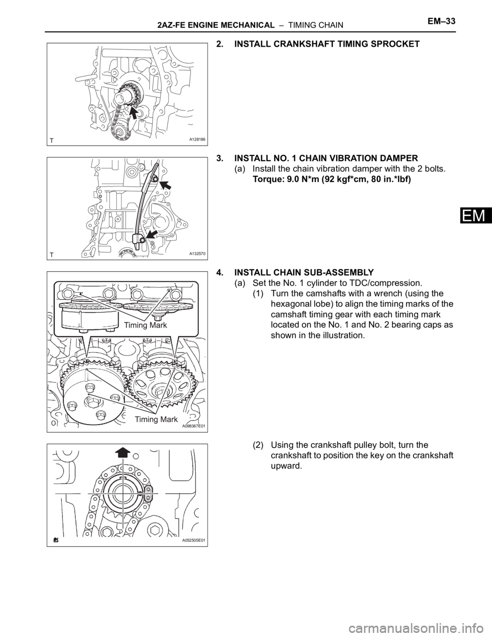
2AZ-FE ENGINE MECHANICAL – TIMING CHAINEM–33
EM
2. INSTALL CRANKSHAFT TIMING SPROCKET
3. INSTALL NO. 1 CHAIN VIBRATION DAMPER
(a) Install the chain vibration damper with the 2 bolts.
Torque: 9.0 N*m (92 kgf*cm, 80 in.*lbf)
4. INSTALL CHAIN SUB-ASSEMBLY
(a) Set the No. 1 cylinder to TDC/compression.
(1) Turn the camshafts with a wrench (using the
hexagonal lobe) to align the timing marks of the
camshaft timing gear with each timing mark
located on the No. 1 and No. 2 bearing caps as
shown in the illustration.
(2) Using the crankshaft pulley bolt, turn the
crankshaft to position the key on the crankshaft
upward.
A128186
A132570
A098367E01
A052505E01
Page 603 of 2000
2AZ-FE ENGINE MECHANICAL – CYLINDER HEADEM–59
EM
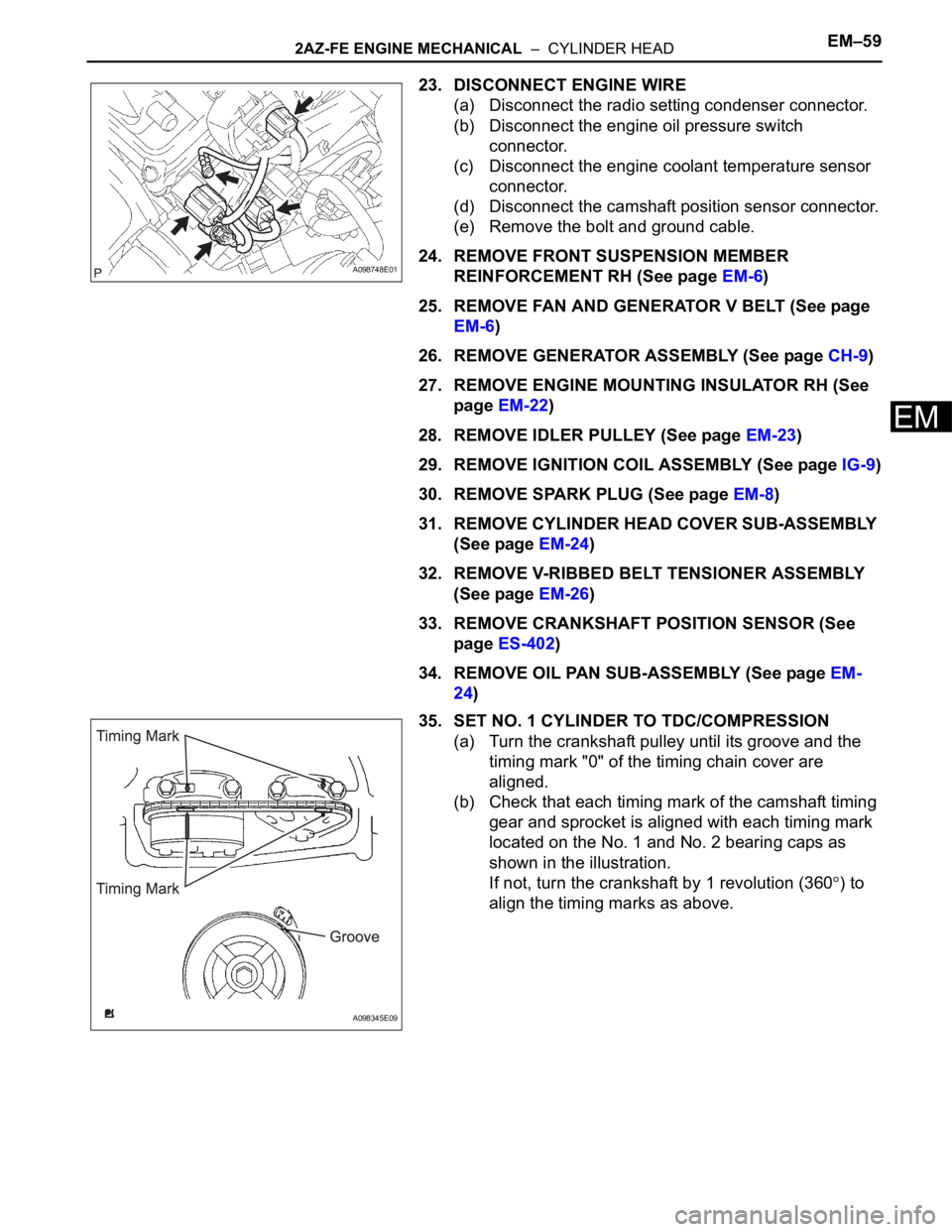
23. DISCONNECT ENGINE WIRE
(a) Disconnect the radio setting condenser connector.
(b) Disconnect the engine oil pressure switch
connector.
(c) Disconnect the engine coolant temperature sensor
connector.
(d) Disconnect the camshaft position sensor connector.
(e) Remove the bolt and ground cable.
24. REMOVE FRONT SUSPENSION MEMBER
REINFORCEMENT RH (See page EM-6)
25. REMOVE FAN AND GENERATOR V BELT (See page
EM-6)
26. REMOVE GENERATOR ASSEMBLY (See page CH-9)
27. REMOVE ENGINE MOUNTING INSULATOR RH (See
page EM-22)
28. REMOVE IDLER PULLEY (See page EM-23)
29. REMOVE IGNITION COIL ASSEMBLY (See page IG-9)
30. REMOVE SPARK PLUG (See page EM-8)
31. REMOVE CYLINDER HEAD COVER SUB-ASSEMBLY
(See page EM-24)
32. REMOVE V-RIBBED BELT TENSIONER ASSEMBLY
(See page EM-26)
33. REMOVE CRANKSHAFT POSITION SENSOR (See
page ES-402)
34. REMOVE OIL PAN SUB-ASSEMBLY (See page EM-
24)
35. SET NO. 1 CYLINDER TO TDC/COMPRESSION
(a) Turn the crankshaft pulley until its groove and the
timing mark "0" of the timing chain cover are
aligned.
(b) Check that each timing mark of the camshaft timing
gear and sprocket is aligned with each timing mark
located on the No. 1 and No. 2 bearing caps as
shown in the illustration.
If not, turn the crankshaft by 1 revolution (360
) to
align the timing marks as above.
A098748E01
A098345E09
Page 692 of 2000
2GR-FE ENGINE MECHANICAL – ENGINE UNITEM–55
EM
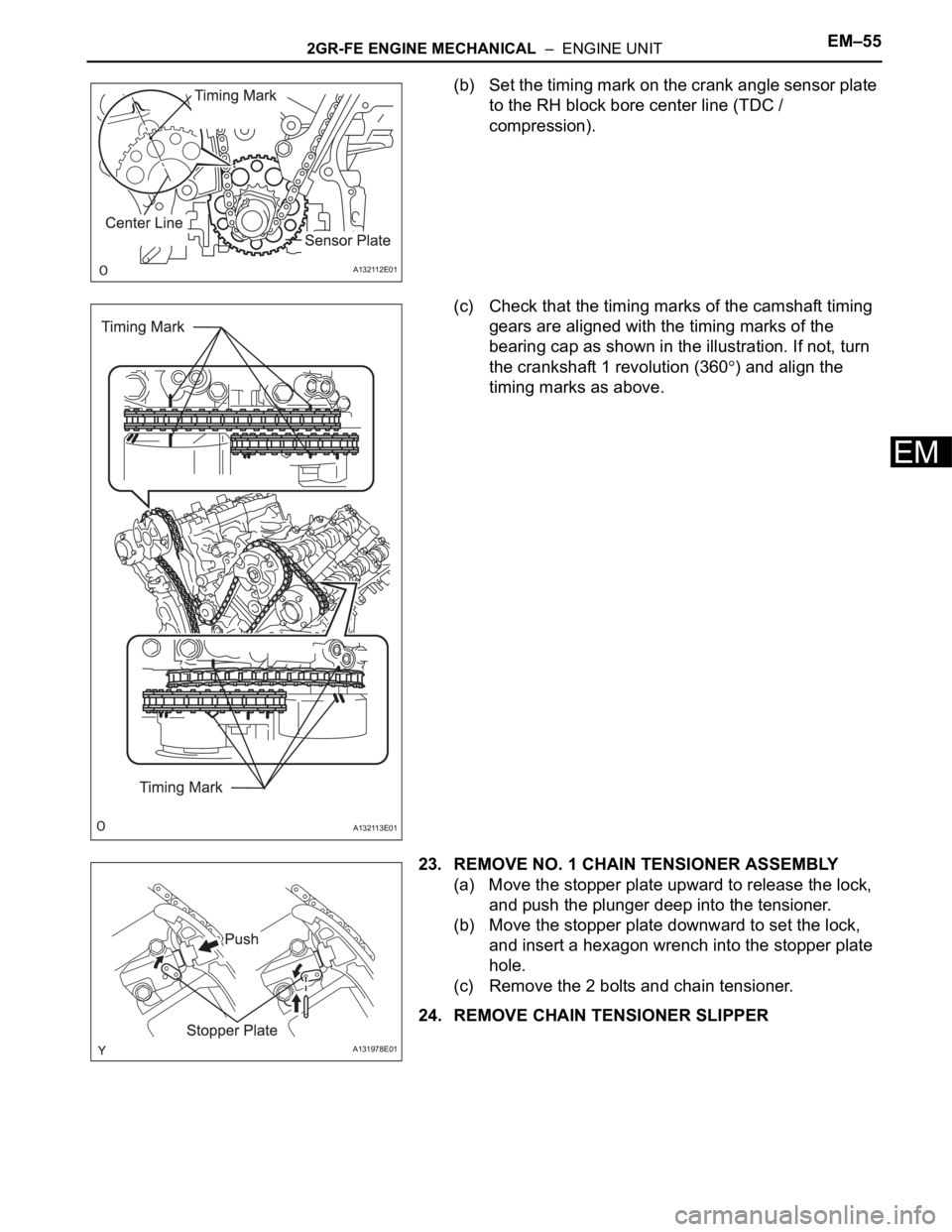
(b) Set the timing mark on the crank angle sensor plate
to the RH block bore center line (TDC /
compression).
(c) Check that the timing marks of the camshaft timing
gears are aligned with the timing marks of the
bearing cap as shown in the illustration. If not, turn
the crankshaft 1 revolution (360
) and align the
timing marks as above.
23. REMOVE NO. 1 CHAIN TENSIONER ASSEMBLY
(a) Move the stopper plate upward to release the lock,
and push the plunger deep into the tensioner.
(b) Move the stopper plate downward to set the lock,
and insert a hexagon wrench into the stopper plate
hole.
(c) Remove the 2 bolts and chain tensioner.
24. REMOVE CHAIN TENSIONER SLIPPER
A132112E01
A132113E01
A131978E01
Page 713 of 2000
EM–762GR-FE ENGINE MECHANICAL – ENGINE UNIT
EM
INSPECTION
1. INSPECT VALVE LASH ADJUSTER ASSEMBLY
NOTICE:
• Keep the lash adjuster free from dirt and foreign
objects.
• Only use clean engine oil.
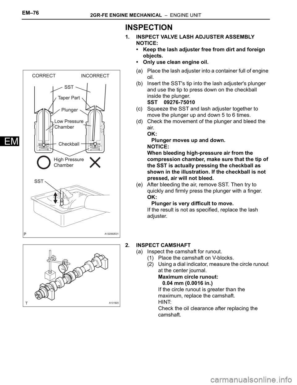
(a) Place the lash adjuster into a container full of engine
oil.
(b) Insert the SST's tip into the lash adjuster's plunger
and use the tip to press down on the checkball
inside the plunger.
SST 09276-75010
(c) Squeeze the SST and lash adjuster together to
move the plunger up and down 5 to 6 times.
(d) Check the movement of the plunger and bleed the
air.
OK:
Plunger moves up and down.
NOTICE:
When bleeding high-pressure air from the
compression chamber, make sure that the tip of
the SST is actually pressing the checkball as
shown in the illustration. If the checkball is not
pressed, air will not bleed.
(e) After bleeding the air, remove SST. Then try to
quickly and firmly press the plunger with a finger.
OK:
Plunger is very difficult to move.
If the result is not as specified, replace the lash
adjuster.
2. INSPECT CAMSHAFT
(a) Inspect the camshaft for runout.
(1) Place the camshaft on V-blocks.
(2) Using a dial indicator, measure the circle runout
at the center journal.
Maximum circle runout:
0.04 mm (0.0016 in.)
If the circle runout is greater than the
maximum, replace the camshaft.
HINT:
Check the oil clearance after replacing the
camshaft.
A132092E01
A131920