compression ratio TOYOTA RAV4 2006 Service User Guide
[x] Cancel search | Manufacturer: TOYOTA, Model Year: 2006, Model line: RAV4, Model: TOYOTA RAV4 2006Pages: 2000, PDF Size: 45.84 MB
Page 744 of 2000
2GR-FE ENGINE MECHANICAL – ENGINE UNITEM–107
EM
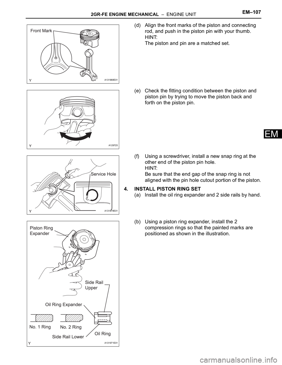
(d) Align the front marks of the piston and connecting
rod, and push in the piston pin with your thumb.
HINT:
The piston and pin are a matched set.
(e) Check the fitting condition between the piston and
piston pin by trying to move the piston back and
forth on the piston pin.
(f) Using a screwdriver, install a new snap ring at the
other end of the piston pin hole.
HINT:
Be sure that the end gap of the snap ring is not
aligned with the pin hole cutout portion of the piston.
4. INSTALL PISTON RING SET
(a) Install the oil ring expander and 2 side rails by hand.
(b) Using a piston ring expander, install the 2
compression rings so that the painted marks are
positioned as shown in the illustration.
A131968E01
A129725
A131879E01
A131971E01
Page 751 of 2000
EM–1142GR-FE ENGINE MECHANICAL – ENGINE UNIT
EM
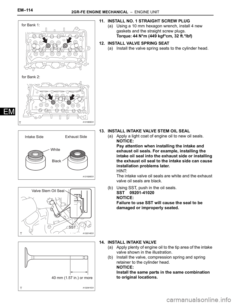
11. INSTALL NO. 1 STRAIGHT SCREW PLUG
(a) Using a 10 mm hexagon wrench, install 4 new
gaskets and the straight screw plugs.
Torque: 44 N*m (449 kgf*cm, 32 ft.*lbf)
12. INSTALL VALVE SPRING SEAT
(a) Install the valve spring seats to the cylinder head.
13. INSTALL INTAKE VALVE STEM OIL SEAL
(a) Apply a light coat of engine oil to new oil seals.
NOTICE:
Pay attention when installing the intake and
exhaust oil seals. For example, installing the
intake oil seal into the exhaust side or installing
the exhaust oil seal to the intake side can cause
installation problems later.
HINT:
The intake valve oil seals are white and the exhaust
valve oil seals are black.
(b) Using SST, push in the oil seals.
SST 09201-41020
NOTICE:
Failure to use SST will cause the seal to be
damaged or improperly seated.
14. INSTALL INTAKE VALVE
(a) Apply plenty of engine oil to the tip area of the intake
valve shown in the illustration.
(b) Install the valve, compression spring and spring
retainer to the cylinder head.
NOTICE:
Install the same parts in the same combination
to original locations.
A131995E01
A131926E01
A132014E01
A132041E01
Page 752 of 2000
2GR-FE ENGINE MECHANICAL – ENGINE UNITEM–115
EM
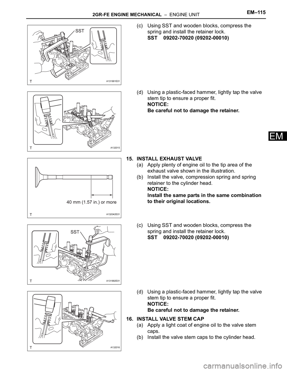
(c) Using SST and wooden blocks, compress the
spring and install the retainer lock.
SST 09202-70020 (09202-00010)
(d) Using a plastic-faced hammer, lightly tap the valve
stem tip to ensure a proper fit.
NOTICE:
Be careful not to damage the retainer.
15. INSTALL EXHAUST VALVE
(a) Apply plenty of engine oil to the tip area of the
exhaust valve shown in the illustration.
(b) Install the valve, compression spring and spring
retainer to the cylinder head.
NOTICE:
Install the same parts in the same combination
to their original locations.
(c) Using SST and wooden blocks, compress the
spring and install the retainer lock.
SST 09202-70020 (09202-00010)
(d) Using a plastic-faced hammer, lightly tap the valve
stem tip to ensure a proper fit.
NOTICE:
Be careful not to damage the retainer.
16. INSTALL VALVE STEM CAP
(a) Apply a light coat of engine oil to the valve stem
caps.
(b) Install the valve stem caps to the cylinder head.
A131991E01
A132015
A132042E01
A131992E01
A132016
Page 761 of 2000
EM–1242GR-FE ENGINE MECHANICAL – ENGINE UNIT
EM
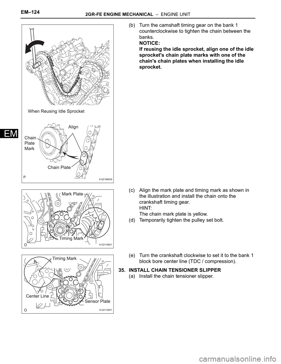
(b) Turn the camshaft timing gear on the bank 1
counterclockwise to tighten the chain between the
banks.
NOTICE:
If reusing the idle sprocket, align one of the idle
sprocket's chain plate marks with one of the
chain's chain plates when installing the idle
sprocket.
(c) Align the mark plate and timing mark as shown in
the illustration and install the chain onto the
crankshaft timing gear.
HINT:
The chain mark plate is yellow.
(d) Temporarily tighten the pulley set bolt.
(e) Turn the crankshaft clockwise to set it to the bank 1
block bore center line (TDC / compression).
35. INSTALL CHAIN TENSIONER SLIPPER
(a) Install the chain tensioner slipper.
A122184E05
A132116E01
A132112E01
Page 763 of 2000
EM–1262GR-FE ENGINE MECHANICAL – ENGINE UNIT
EM
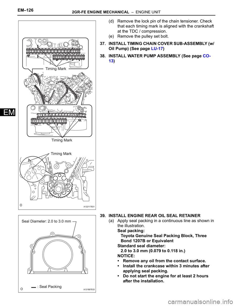
(d) Remove the lock pin of the chain tensioner. Check
that each timing mark is aligned with the crankshaft
at the TDC / compression.
(e) Remove the pulley set bolt.
37. INSTALL TIMING CHAIN COVER SUB-ASSEMBLY (w/
Oil Pump) (See page LU-17)
38. INSTALL WATER PUMP ASSEMBLY (See page CO-
13)
39. INSTALL ENGINE REAR OIL SEAL RETAINER
(a) Apply seal packing in a continuous line as shown in
the illustration.
Seal packing:
Toyota Genuine Seal Packing Block, Three
Bond 1207B or Equivalent
Standard seal diameter:
2.0 to 3.0 mm (0.079 to 0.118 in.)
NOTICE:
• Remove any oil from the contact surface.
• Install the crankcase within 3 minutes after
applying seal packing.
• Do not start the engine for at least 2 hours
after the installation.
A132117E01
A131897E03