coolant reservoir TOYOTA RAV4 2006 Service Repair Manual
[x] Cancel search | Manufacturer: TOYOTA, Model Year: 2006, Model line: RAV4, Model: TOYOTA RAV4 2006Pages: 2000, PDF Size: 45.84 MB
Page 13 of 2000

ENGINE - 2AZ-FE ENGINE
01NEG35Y
Throttle Body
To H e a t e r C o r e
To R a d i a t o r
Thermostat
From Radiator Wa t e r P u m pBypass Passage
01NEG59Y
Bypass PassageCylinder Head
Wa t e r P u m p
Cylinder Block
Thermostat
Reservoir
Ta n k
RadiatorThrottle
BodyHeater Core EG-16
COOLING SYSTEM
The cooling system uses a pressurized forced-circulation system with pressurized reservoir tank.
A thermostat with a bypass valve is located on the water inlet housing to maintain suitable temperature
distribution in the cooling system.
An aluminum radiator core is used for weight reduction.
The flow of the engine coolant makes a U-turn in the cylinder block to ensure a smooth flow of the engine
coolant. In addition, a bypass passage is enclosed in the cylinder head and the cylinder block.
Warm water from the engine is sent to the throttle body to prevent freeze-up.
The TOYOTA genuine Super Long Life Coolant (SLLC) is used.
System Diagram
Page 84 of 2000
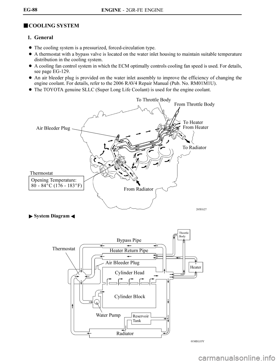
ENGINE - 2GR-FE ENGINE
285EG27
Air Bleeder PlugTo Throttle Body
From Throttle Body
To H e a t e r
From Heater
To Radiator
From Radiator Thermostat
Opening Temperature:
80 - 84
C (176 - 183F)
01MEG35Y
ThermostatBypass Pipe
Heater Return Pipe
Air Bleeder Plug
Cylinder Head
Cylinder Block
Wa t e r P u m p
Radiator
Throttle
Body
Heater
Reservoir
Ta n k
EG-88
COOLING SYSTEM
1. General
The cooling system is a pressurized, forced-circulation type.
A thermostat with a bypass valve is located on the water inlet housing to maintain suitable temperature
distribution in the cooling system.
A cooling fan control system in which the ECM optimally controls cooling fan speed is used. For details,
see page EG-129.
An air bleeder plug is provided on the water inlet assembly to improve the efficiency of changing the
engine coolant. For details, refer to the 2006 RAV4 Repair Manual (Pub. No. RM01M1U).
The TOYOTA genuine SLLC (Super Long Life Coolant) is used for the engine coolant.
System Diagram
Page 182 of 2000

MAINTENANCE – UNDER HOODMA–7
MA
GENERAL MAINTENANCE
(2006/01- )
1. GENERAL NOTES
• Maintenance requirements vary depending on the
country.
• Check the maintenance schedule in the owner's
manual supplement.
• Following the maintenance schedule is mandatory.
• Determine the appropriate time to service the vehicle
using either miles driven or time elapsed, whichever
reaches the specification first.
• Maintain similar intervals between periodic
maintenance, unless otherwise noted.
• Failing to check each vehicle part could lead to poor
engine performance and increase exhaust emissions.
2. WINDSHIELD WASHER FLUID
(a) Check that there is sufficient fluid in the tank.
3. ENGINE COOLANT LEVEL
(a) Check that the coolant level is between the "FULL"
and "LOW" lines on the see-through reservoir.
4. RADIATOR AND HOSES
(a) Check that the front of the radiator is clean and not
blocked by leaves, dirt or bugs.
(b) Check the hoses for cracks, kinks, rot or loose
connections.
5. BATTERY ELECTROLYTE LEVEL
(a) Check that the electrolyte level of all the battery
cells is between the upper and lower level lines on
the case.
HINT:
If the electrolyte level is difficult to see, lightly shake
the vehicle.
6. BRAKE FLUID LEVEL
(a) Check that the brake fluid levels are near the upper
level lines on the see-through reservoirs.
7. ENGINE DRIVE BELT
(a) Check the drive belt for fraying, cracks, wear or
oiliness.
8. ENGINE OIL LEVEL
(a) Check the level on the dipstick with the engine
stopped.
9. AUTOMATIC TRANSAXLE FLUID LEVEL
10. EXHAUST SYSTEM
(a) Check for unusual exhaust sounds or abnormal
exhaust fumes. Inspect the cause and repair it.
Type See procedures
U151E See page AX-126
U151F See page AX-126
Page 383 of 2000

SERVICE SPECIFICATIONS – 2GR-FE ENGINE MECHANICALSS–21
SS
TORQUE SPECIFICATIONS
Part Tightened N*m kgf*cm ft.*lbf
Front suspension member reinforcement RH x Front
crossmember95 969 70
Front suspension member reinforcement RH x Front
suspension crossmember95 969 70
Radiator reservoir tank x Bract 5.0 51 44 in.*lbf
Engine coolant temperature sensor x Water outlet 20 204 14
Engine oil pressure sensor x Oil pan 21 214 15
No. 1 front engine mounting bracket LH x Timing chain
cover54 551 40
No. 2 idler pulley x Timing chain cover 43 438 32
No. 2 timing gear cover x Timing chain cover 6.0 61 53 in.*lbf
V-ribbed belt tensioner x Timing chain cover 43 438 32
V-ribbed belt tensioner x Cylinder block 43 438 32
Drive shaft bearing bracket x Cylinder block 64 653 47
Exhaust manifold LH x Cylinder head 21 214 15
No. 2 exhaust heat insulator x Exhaust manifold 8.5 87 75 in.*lbf
No. 2 manifold stay x Exhaust manifold 34 347 25
No. 2 manifold stay x Cylinder block 34 347 25
No. 1 oil dipstick guide x Cylinder block 21 214 15
No. 2 oil dipstick guide x Cylinder head 21 214 15
Exhaust manifold RH x Cylinder head 21 214 15
Intake manifold x Cylinder head 21 214 15
No. 2 engine mounting stay RH x Intake manifold 21 214 15
No. 2 engine mounting stay RH x Timing chain cover 21 214 15
Ignition coil x Cylinder head cover 10 102 7
Intake air surge tank x
Intake manifold5 mm hexagon wrench 18 184 13
for Bolt 21 214 15
for Nut 16 163 12
Vacuum hose clamp x Intake air surge tank 5.4 55 48 in.*lbf
Drive plate and ring gear x Crankshaft 178 1,815 132
Engine mounting bracket RR x Engine mounting
insulator RR95 969 70
Engine mounting bracket FR x Engine mounting
insulator FR145 1,479 107
Engine mounting bracket LH x Engine mounting
insulator LH56 571 41
Engine mounting insulator
RH x Front No. 1 engine
mounting bracketfor Bolt and nut A 95 969 70
for Nut B 52 530 38
Front crossmember x
Bodyfor Bolt A 96 979 71
Front suspension member
x Bodyfor Bolt B 145 1,478 107
Front suspension member
brace rear x Bodyfor Bolt C 145 1,478 107
for Bolt D 93 948 69
Air cleaner case x Engine mounting insulator LH 5.0 51 44 in.*lbf
Battery bracket reinforcement x Body 19 194 14
Front battery bracket x Body 19 194 14
Front battery bracket x Battery bracket reinforcement 19 194 14
Battery clamp x Body 5.0 51 44 in.*lbf
Page 630 of 2000
EM–862AZ-FE ENGINE MECHANICAL – CYLINDER HEAD
EM
22. INSTALL ENGINE MOUNTING INSULATOR RH (See
page EM-41)
23. INSTALL RADIATOR RESERVOIR (See page EM-112)
24. INSTALL GENERATOR ASSEMBLY (See page CH-15)
25. INSTALL FAN AND GENERATOR V BELT (See page
EM-7)
26. INSTALL FRONT SUSPENSION MEMBER
REINFORCEMENT RH (See page EM-7)
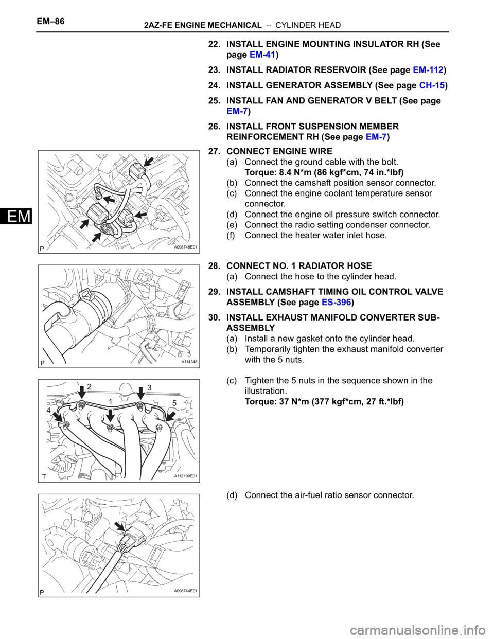
27. CONNECT ENGINE WIRE
(a) Connect the ground cable with the bolt.
Torque: 8.4 N*m (86 kgf*cm, 74 in.*lbf)
(b) Connect the camshaft position sensor connector.
(c) Connect the engine coolant temperature sensor
connector.
(d) Connect the engine oil pressure switch connector.
(e) Connect the radio setting condenser connector.
(f) Connect the heater water inlet hose.
28. CONNECT NO. 1 RADIATOR HOSE
(a) Connect the hose to the cylinder head.
29. INSTALL CAMSHAFT TIMING OIL CONTROL VALVE
ASSEMBLY (See page ES-396)
30. INSTALL EXHAUST MANIFOLD CONVERTER SUB-
ASSEMBLY
(a) Install a new gasket onto the cylinder head.
(b) Temporarily tighten the exhaust manifold converter
with the 5 nuts.
(c) Tighten the 5 nuts in the sequence shown in the
illustration.
Torque: 37 N*m (377 kgf*cm, 27 ft.*lbf)
(d) Connect the air-fuel ratio sensor connector.
A098748E01
A114348
A112190E01
A098744E01
Page 633 of 2000
EM–982AZ-FE ENGINE MECHANICAL – ENGINE ASSEMBLY
EM
REMOVAL
1. DISCHARGE FUEL SYSTEM PRESSURE (See page
FU-9)
2. DISCONNECT CABLE FROM NEGATIVE BATTERY
TERMINAL
CAUTION:
Wait at least 90 seconds after disconnecting the
cable from the negative (-) battery terminal to
prevent airbag and seat belt pretensioner activation.
3. REMOVE HOOD SUB-ASSEMBLY (See page ED-4)
4. REMOVE RADIATOR SUPPORT OPENING COVER
5. REMOVE BATTERY CLAMP SUB-ASSEMBLY
(a) Loosen the bolt and nut, and remove the battery
clamp.
6. REMOVE BATTERY
7. REMOVE BATTERY TRAY
8. REMOVE FRONT WHEEL
9. REMOVE NO. 1 ENGINE UNDER COVER
10. REMOVE NO. 2 ENGINE UNDER COVER
11. REMOVE FRONT FENDER APRON RH
12. REMOVE NO. 1 ENGINE COVER (See page EM-22)
13. DRAIN ENGINE COOLANT (See page CO-6)
14. DRAIN AUTOMATIC TRANSAXLE FLUID
(a) Drain automatic transaxle fluid for U241E (2WD)
(see page AX-146).
(b) Drain automatic transaxle fluid for U140F (4WD)
(see page AX-147).
15. REMOVE RADIATOR ASSEMBLY
(a) Remove the radiator (see page CO-29).
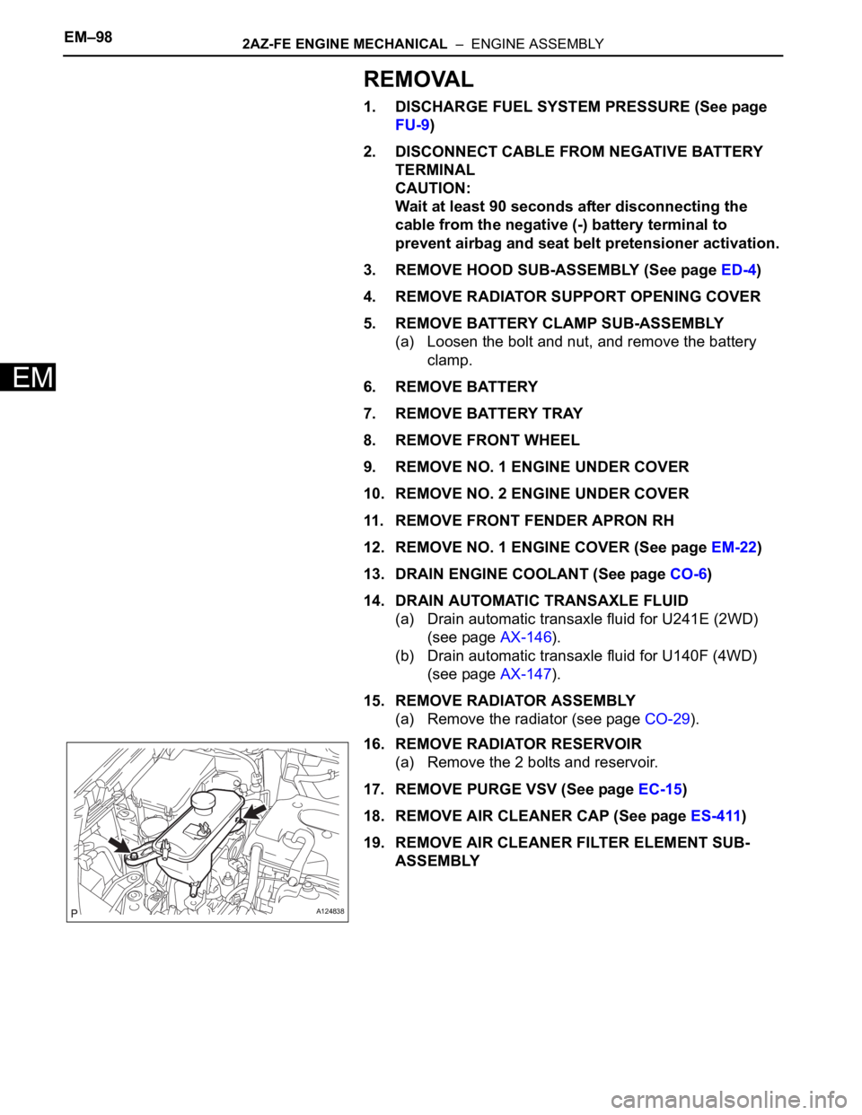
16. REMOVE RADIATOR RESERVOIR
(a) Remove the 2 bolts and reservoir.
17. REMOVE PURGE VSV (See page EC-15)
18. REMOVE AIR CLEANER CAP (See page ES-411)
19. REMOVE AIR CLEANER FILTER ELEMENT SUB-
ASSEMBLY
A124838
Page 648 of 2000
2AZ-FE ENGINE MECHANICAL – ENGINE ASSEMBLYEM–113
EM
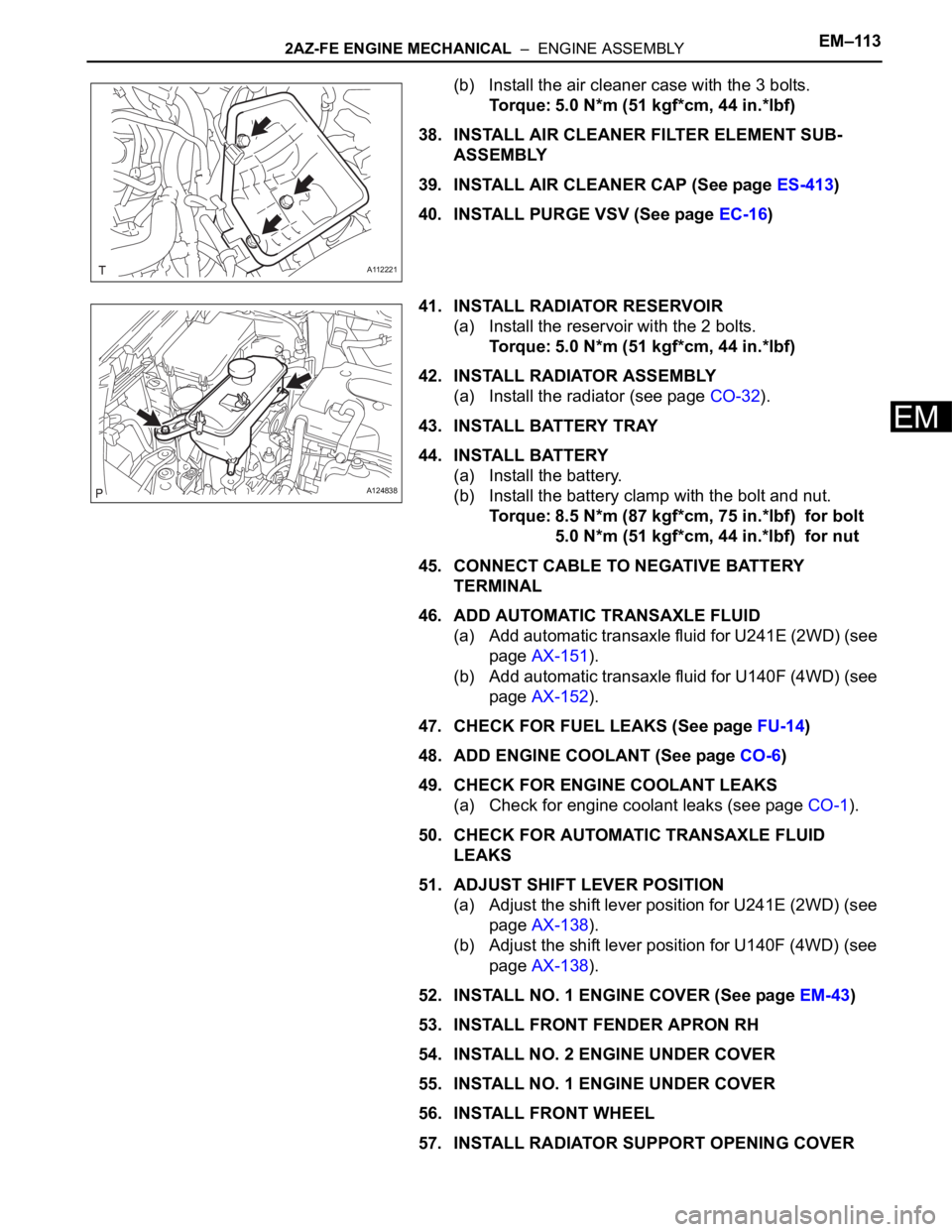
(b) Install the air cleaner case with the 3 bolts.
Torque: 5.0 N*m (51 kgf*cm, 44 in.*lbf)
38. INSTALL AIR CLEANER FILTER ELEMENT SUB-
ASSEMBLY
39. INSTALL AIR CLEANER CAP (See page ES-413)
40. INSTALL PURGE VSV (See page EC-16)
41. INSTALL RADIATOR RESERVOIR
(a) Install the reservoir with the 2 bolts.
Torque: 5.0 N*m (51 kgf*cm, 44 in.*lbf)
42. INSTALL RADIATOR ASSEMBLY
(a) Install the radiator (see page CO-32).
43. INSTALL BATTERY TRAY
44. INSTALL BATTERY
(a) Install the battery.
(b) Install the battery clamp with the bolt and nut.
Torque: 8.5 N*m (87 kgf*cm, 75 in.*lbf) for bolt
5.0 N*m (51 kgf*cm, 44 in.*lbf) for nut
45. CONNECT CABLE TO NEGATIVE BATTERY
TERMINAL
46. ADD AUTOMATIC TRANSAXLE FLUID
(a) Add automatic transaxle fluid for U241E (2WD) (see
page AX-151).
(b) Add automatic transaxle fluid for U140F (4WD) (see
page AX-152).
47. CHECK FOR FUEL LEAKS (See page FU-14)
48. ADD ENGINE COOLANT (See page CO-6)
49. CHECK FOR ENGINE COOLANT LEAKS
(a) Check for engine coolant leaks (see page CO-1).
50. CHECK FOR AUTOMATIC TRANSAXLE FLUID
LEAKS
51. ADJUST SHIFT LEVER POSITION
(a) Adjust the shift lever position for U241E (2WD) (see
page AX-138).
(b) Adjust the shift lever position for U140F (4WD) (see
page AX-138).
52. INSTALL NO. 1 ENGINE COVER (See page EM-43)
53. INSTALL FRONT FENDER APRON RH
54. INSTALL NO. 2 ENGINE UNDER COVER
55. INSTALL NO. 1 ENGINE UNDER COVER
56. INSTALL FRONT WHEEL
57. INSTALL RADIATOR SUPPORT OPENING COVER
A112221
A124838
Page 847 of 2000
2AZ-FE COOLING – RADIATORCO–29
CO
REMOVAL
1. DISCONNECT CABLE FROM NEGATIVE BATTERY
TERMINAL
CAUTION:
Wait at least 90 seconds after disconnecting the
cable from the negative (-) battery terminal to
prevent airbag and seat belt pretensioner activation.
2. REMOVE RADIATOR SUPPORT OPENING COVER
3. REMOVE BATTERY CLAMP
(a) Remove the bolt, nut and clamp.
4. REMOVE BATTERY
5. REMOVE NO. 1 ENGINE UNDER COVER
6. DRAIN ENGINE COOLANT (See page CO-6)
7. REMOVE RADIATOR GRILLE SUB-ASSEMBLY (See
page ET-6)
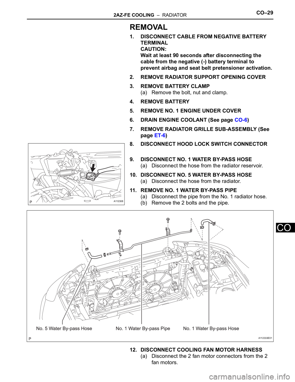
8. DISCONNECT HOOD LOCK SWITCH CONNECTOR
9. DISCONNECT NO. 1 WATER BY-PASS HOSE
(a) Disconnect the hose from the radiator reservoir.
10. DISCONNECT NO. 5 WATER BY-PASS HOSE
(a) Disconnect the hose from the radiator.
11. REMOVE NO. 1 WATER BY-PASS PIPE
(a) Disconnect the pipe from the No. 1 radiator hose.
(b) Remove the 2 bolts and the pipe.
12. DISCONNECT COOLING FAN MOTOR HARNESS
(a) Disconnect the 2 fan motor connectors from the 2
fan motors.
A112308
A112333E01
Page 859 of 2000
2GR-FE COOLING – THERMOSTATCO–19
CO
REMOVAL
1. REMOVE FRONT WHEEL RH
2. REMOVE NO. 1 ENGINE UNDER COVER (See page
EM-21)
3. REMOVE ENGINE UNDER COVER REAR RH (See
page EM-21)
4. REMOVE FRONT SUSPENSION MEMBER
REINFORCEMENT RH (See page EM-7)
5. DRAIN ENGINE COOLANT (See page CO-8)
6. REMOVE V-BANK COVER SUB-ASSEMBLY (See
page EM-21)
7. REMOVE RADIATOR SUPPORT OPENING COVER
(See page EM-22)
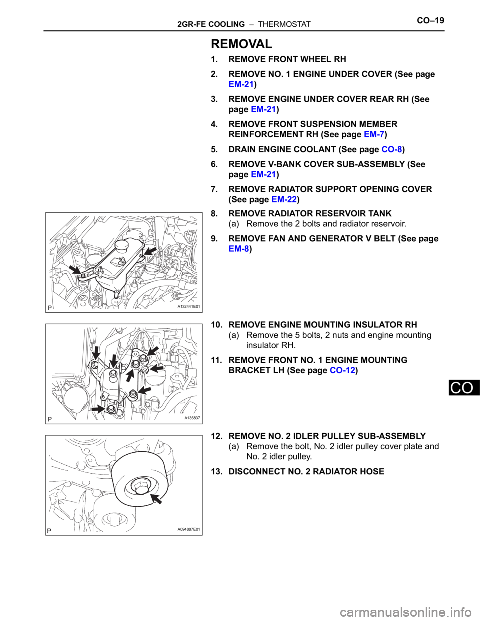
8. REMOVE RADIATOR RESERVOIR TANK
(a) Remove the 2 bolts and radiator reservoir.
9. REMOVE FAN AND GENERATOR V BELT (See page
EM-8)
10. REMOVE ENGINE MOUNTING INSULATOR RH
(a) Remove the 5 bolts, 2 nuts and engine mounting
insulator RH.
11. REMOVE FRONT NO. 1 ENGINE MOUNTING
BRACKET LH (See page CO-12)
12. REMOVE NO. 2 IDLER PULLEY SUB-ASSEMBLY
(a) Remove the bolt, No. 2 idler pulley cover plate and
No. 2 idler pulley.
13. DISCONNECT NO. 2 RADIATOR HOSE
A132441E01
A136837
A094887E01
Page 862 of 2000
CO–222GR-FE COOLING – THERMOSTAT
CO
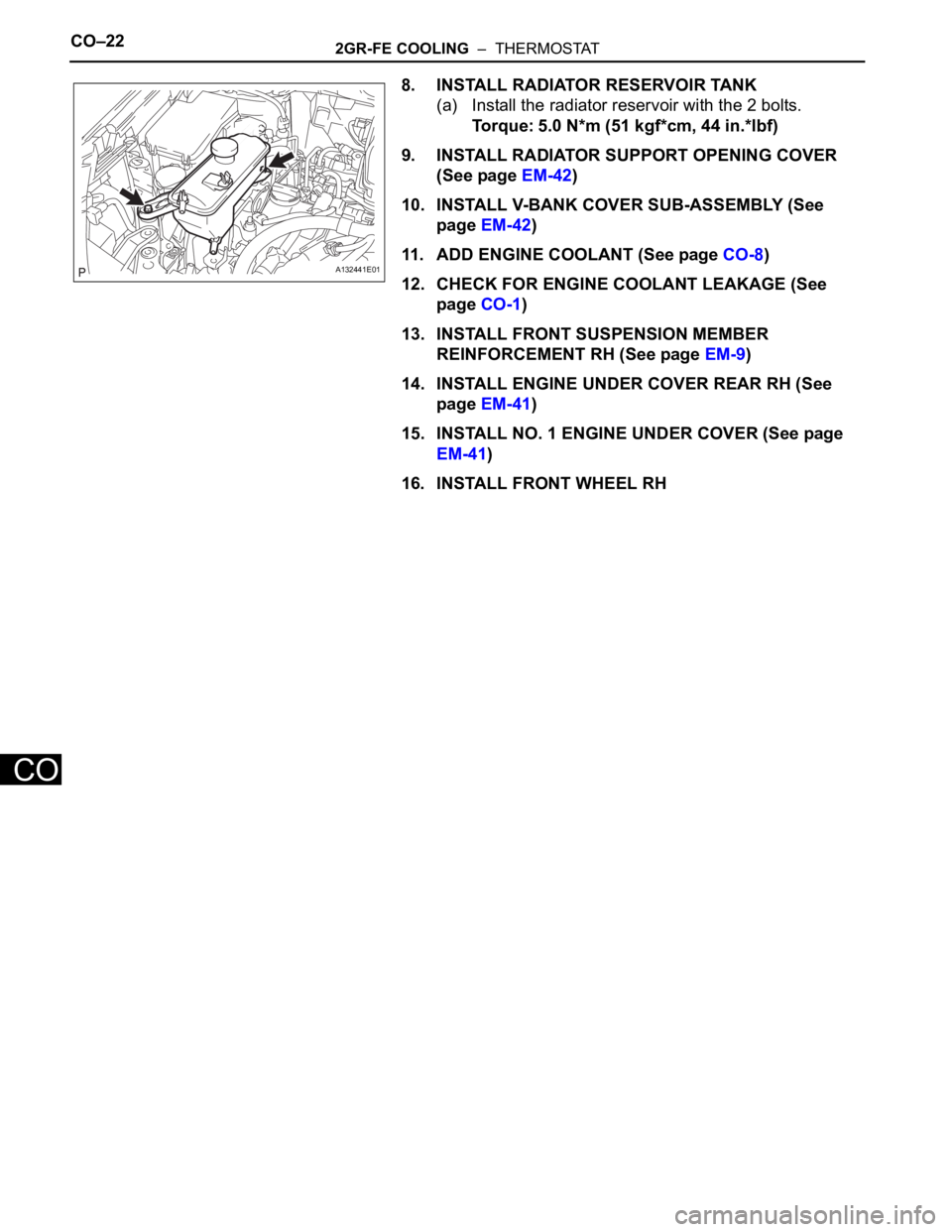
8. INSTALL RADIATOR RESERVOIR TANK
(a) Install the radiator reservoir with the 2 bolts.
Torque: 5.0 N*m (51 kgf*cm, 44 in.*lbf)
9. INSTALL RADIATOR SUPPORT OPENING COVER
(See page EM-42)
10. INSTALL V-BANK COVER SUB-ASSEMBLY (See
page EM-42)
11. ADD ENGINE COOLANT (See page CO-8)
12. CHECK FOR ENGINE COOLANT LEAKAGE (See
page CO-1)
13. INSTALL FRONT SUSPENSION MEMBER
REINFORCEMENT RH (See page EM-9)
14. INSTALL ENGINE UNDER COVER REAR RH (See
page EM-41)
15. INSTALL NO. 1 ENGINE UNDER COVER (See page
EM-41)
16. INSTALL FRONT WHEEL RH
A132441E01