manual transmission TOYOTA RAV4 2006 Service Repair Manual
[x] Cancel search | Manufacturer: TOYOTA, Model Year: 2006, Model line: RAV4, Model: TOYOTA RAV4 2006Pages: 2000, PDF Size: 45.84 MB
Page 167 of 2000
IN–22INTRODUCTION – REPAIR INSTRUCTION
IN
VEHICLE LIFT AND SUPPORT
LOCATIONS
1. NOTICE ABOUT VEHICLE CONDITION WHEN
JACKING UP VEHICLE
(a) The vehicle must be unloaded before jacking up /
lifting up the vehicle. Never jack up / lift up a heavily
loaded vehicle.
(b) When removing heavy parts such as the engine and
transmission, the center of gravity of the vehicle
may shift. To stabilize the vehicle, place a balance
weight in a location where it will not roll or shift, or
use a mission jack to hold the jacking support.
2. NOTICE FOR USING 4 POST LIFT
(a) Follow the safety procedures outlined in the lift
instruction manual.
(b) Use precautionary measures to prevent the free
wheel beam from damaging tires or wheels.
(c) Use wheel chocks to secure the vehicle.
3. NOTICE FOR USING JACK AND SAFETY STAND
(a) Work on a level surface. Use wheel chocks at all
times.
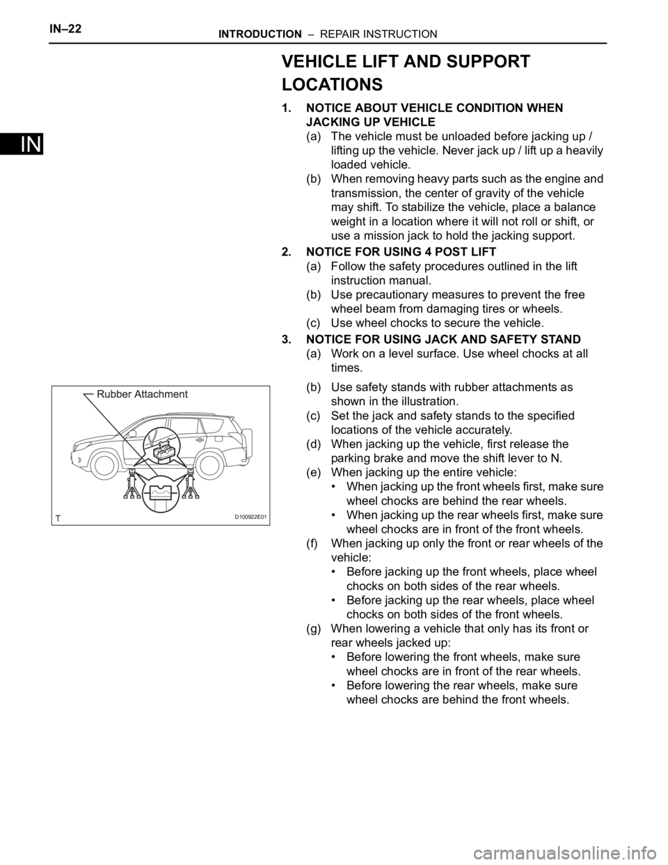
(b) Use safety stands with rubber attachments as
shown in the illustration.
(c) Set the jack and safety stands to the specified
locations of the vehicle accurately.
(d) When jacking up the vehicle, first release the
parking brake and move the shift lever to N.
(e) When jacking up the entire vehicle:
• When jacking up the front wheels first, make sure
wheel chocks are behind the rear wheels.
• When jacking up the rear wheels first, make sure
wheel chocks are in front of the front wheels.
(f) When jacking up only the front or rear wheels of the
vehicle:
• Before jacking up the front wheels, place wheel
chocks on both sides of the rear wheels.
• Before jacking up the rear wheels, place wheel
chocks on both sides of the front wheels.
(g) When lowering a vehicle that only has its front or
rear wheels jacked up:
• Before lowering the front wheels, make sure
wheel chocks are in front of the rear wheels.
• Before lowering the rear wheels, make sure
wheel chocks are behind the front wheels.
D100922E01
Page 180 of 2000

SS–48SERVICE SPECIFICATIONS – U151E AUTOMATIC TRANSMISSION
SS
Parking lock pawl bracket x Transaxle case 20 205 15
Manual detent spring x Transaxle case Bolt A 20 205 15
Bolt B 12 120 9
Automatic transaxle oil pan sub-assembly x Transaxle case 7.6 77 67 in.*lbf
Speed sensor x Transaxle case 11 112 8
Park/neutral start switch x Control shaft lever 13 130 9
Speedometer driven hole cover sub-assembly x Transaxle case 5.5 56 49 in.*lbf
Oil pump body x Stator shaft assembly 9.8 100 87 in.*lbf
Front differential case x Front differential ring gear 95 969 70Part Tightened N*m kgf*cm ft*lbf
Page 387 of 2000

SS–54SERVICE SPECIFICATIONS – U151F AUTOMATIC TRANSMISSION
SS
Automatic transmission case plug x Transaxle case 7.4 75 65 in.*lbf
Parking lock pawl bracket x Transaxle case 20 205 15
Manual detent spring x Transaxle case Bolt A 20 205 15
Bolt B 12 120 9
Automatic transaxle oil pan sub-assembly x Transaxle case 7.6 77 67 in.*lbf
Speed sensor x Transaxle case11 11 2 8
Park/neutral start switch x Control shaft lever 13 130 9
Speedometer driven hole cover sub-assembly x Transaxle case 5.5 56 49 in.*lbf
Oil pump body x Stator shaft assembly 9.8 100 87 in.*lbf
Front differential case x Front differential ring gear 95 969 70Part Tightened N*m kgf*cm ft*lbf
Page 955 of 2000
U140F AUTOMATIC TRANSAXLE – AUTOMATIC TRANSAXLE SYSTEMAX–21
AX
MANUAL SHIFTING TEST
1. MANUAL SHIFTING TEST
HINT:
• Through this test, it can be determined whether the
trouble occurs in the electrical circuit or if it is a
mechanical problem in the transaxle.
• If any abnormalities are found in the following test, the
problem is in the transaxle itself.
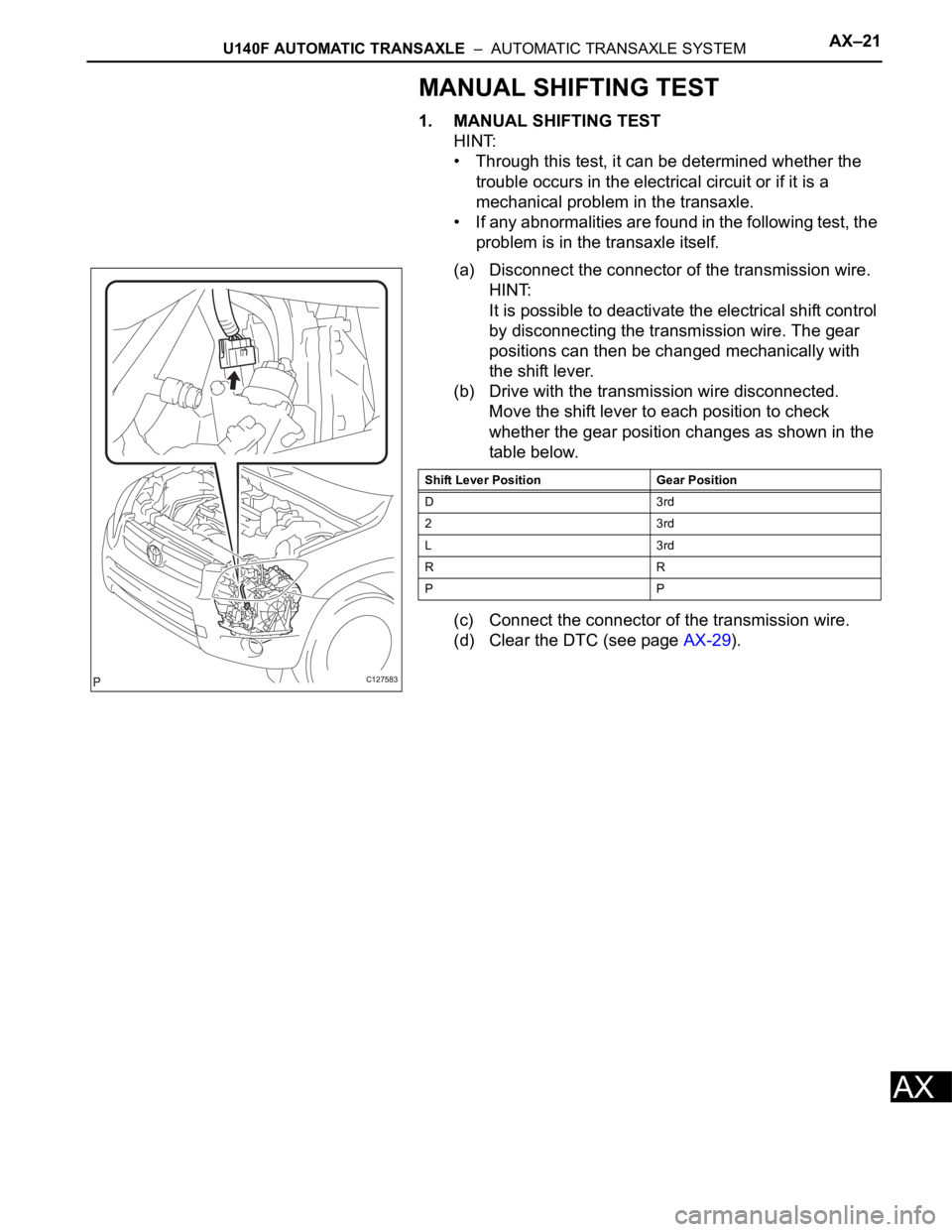
(a) Disconnect the connector of the transmission wire.
HINT:
It is possible to deactivate the electrical shift control
by disconnecting the transmission wire. The gear
positions can then be changed mechanically with
the shift lever.
(b) Drive with the transmission wire disconnected.
Move the shift lever to each position to check
whether the gear position changes as shown in the
table below.
(c) Connect the connector of the transmission wire.
(d) Clear the DTC (see page AX-29).
C127583
Shift Lever Position Gear Position
D3rd
23rd
L3rd
RR
PP
Page 1006 of 2000
AX–212U140F AUTOMATIC TRANSAXLE – AUTOMATIC TRANSAXLE UNIT
AX
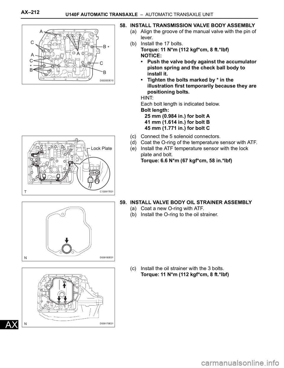
58. INSTALL TRANSMISSION VALVE BODY ASSEMBLY
(a) Align the groove of the manual valve with the pin of
lever.
(b) Install the 17 bolts.
Torque: 11 N*m (112 kgf*cm, 8 ft.*lbf)
NOTICE:
• Push the valve body against the accumulator
piston spring and the check ball body to
install it.
• Tighten the bolts marked by * in the
illustration first temporarily because they are
positioning bolts.
HINT:
Each bolt length is indicated below.
Bolt length:
25 mm (0.984 in.) for bolt A
41 mm (1.614 in.) for bolt B
45 mm (1.771 in.) for bolt C
(c) Connect the 5 solenoid connectors.
(d) Coat the O-ring of the temperature sensor with ATF.
(e) Install the ATF temperature sensor with the lock
plate and bolt.
Torque: 6.6 N*m (67 kgf*cm, 58 in.*lbf)
59. INSTALL VALVE BODY OIL STRAINER ASSEMBLY
(a) Coat a new O-ring with ATF.
(b) Install the O-ring to the oil strainer.
(c) Install the oil strainer with the 3 bolts.
Torque: 11 N*m (112 kgf*cm, 8 ft.*lbf)
D003553E10
C130917E01
D009180E01
D009179E01
Page 1038 of 2000
AX–22U151E AUTOMATIC TRANSAXLE – AUTOMATIC TRANSAXLE SYSTEM
AX
MANUAL SHIFTING TEST
1. MANUAL SHIFTING TEST
HINT:
• Through this test, it can be determined whether the
trouble occurs in the electrical circuit or if it is a
mechanical problem in the transaxle.
• If any abnormalities are found in the following test, the
problem is in the transaxle itself.
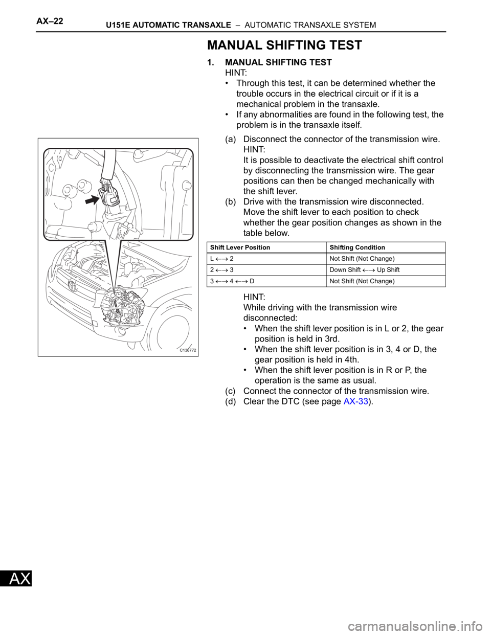
(a) Disconnect the connector of the transmission wire.
HINT:
It is possible to deactivate the electrical shift control
by disconnecting the transmission wire. The gear
positions can then be changed mechanically with
the shift lever.
(b) Drive with the transmission wire disconnected.
Move the shift lever to each position to check
whether the gear position changes as shown in the
table below.
HINT:
While driving with the transmission wire
disconnected:
• When the shift lever position is in L or 2, the gear
position is held in 3rd.
• When the shift lever position is in 3, 4 or D, the
gear position is held in 4th.
• When the shift lever position is in R or P, the
operation is the same as usual.
(c) Connect the connector of the transmission wire.
(d) Clear the DTC (see page AX-33).
C136772
Shift Lever Position Shifting Condition
L
2 Not Shift (Not Change)
2
3 Down Shift Up Shift
3
4 D Not Shift (Not Change)
Page 1113 of 2000
U151E AUTOMATIC TRANSAXLE – AUTOMATIC TRANSAXLE UNITAX–239
AX
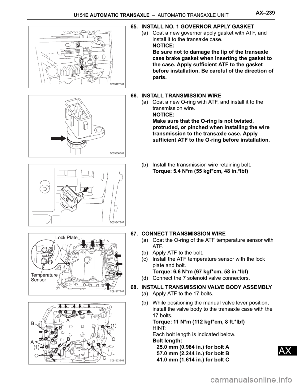
65. INSTALL NO. 1 GOVERNOR APPLY GASKET
(a) Coat a new governor apply gasket with ATF, and
install it to the transaxle case.
NOTICE:
Be sure not to damage the lip of the transaxle
case brake gasket when inserting the gasket to
the case. Apply sufficient ATF to the gasket
before installation. Be careful of the direction of
parts.
66. INSTALL TRANSMISSION WIRE
(a) Coat a new O-ring with ATF, and install it to the
transmission wire.
NOTICE:
Make sure that the O-ring is not twisted,
protruded, or pinched when installing the wire
transmission to the transaxle case. Apply
sufficient ATF to the O-ring before installation.
(b) Install the transmission wire retaining bolt.
Torque: 5.4 N*m (55 kgf*cm, 48 in.*lbf)
67. CONNECT TRANSMISSION WIRE
(a) Coat the O-ring of the ATF temperature sensor with
AT F.
(b) Apply ATF to the bolt.
(c) Install the ATF temperature sensor with the lock
plate and bolt.
Torque: 6.6 N*m (67 kgf*cm, 58 in.*lbf)
(d) Connect the 7 solenoid valve connectors.
68. INSTALL TRANSMISSION VALVE BODY ASSEMBLY
(a) Apply ATF to the 17 bolts.
(b) While positioning the manual valve lever position,
install the valve body to the transaxle case with the
17 bolts.
Torque: 11 N*m (112 kgf*cm, 8 ft.*lbf)
HINT:
Each bolt length is indicated below.
Bolt length:
25.0 mm (0.984 in.) for bolt A
57.0 mm (2.244 in.) for bolt B
41.0 mm (1.614 in.) for bolt C
C083127E01
D003636E02
D003547E07
C091927E07
C091933E02
Page 1141 of 2000
AX–22U151F AUTOMATIC TRANSAXLE – AUTOMATIC TRANSAXLE SYSTEM
AX
MANUAL SHIFTING TEST
1. MANUAL SHIFTING TEST
HINT:
• Through this test, it can be determined whether the
trouble occurs in the electrical circuit or if it is a
mechanical problem in the transaxle.
• If any abnormalities are found in the following test, the
problem is in the transaxle itself.
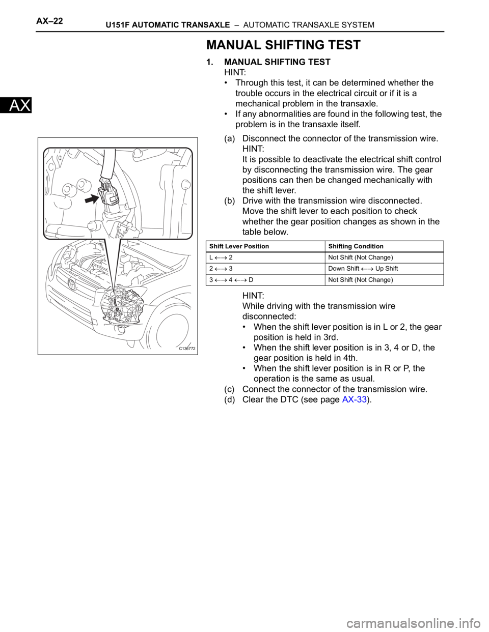
(a) Disconnect the connector of the transmission wire.
HINT:
It is possible to deactivate the electrical shift control
by disconnecting the transmission wire. The gear
positions can then be changed mechanically with
the shift lever.
(b) Drive with the transmission wire disconnected.
Move the shift lever to each position to check
whether the gear position changes as shown in the
table below.
HINT:
While driving with the transmission wire
disconnected:
• When the shift lever position is in L or 2, the gear
position is held in 3rd.
• When the shift lever position is in 3, 4 or D, the
gear position is held in 4th.
• When the shift lever position is in R or P, the
operation is the same as usual.
(c) Connect the connector of the transmission wire.
(d) Clear the DTC (see page AX-33).
C136772
Shift Lever Position Shifting Condition
L
2 Not Shift (Not Change)
2
3 Down Shift Up Shift
3
4 D Not Shift (Not Change)
Page 1218 of 2000
AX–240U151F AUTOMATIC TRANSAXLE – AUTOMATIC TRANSAXLE UNIT
AX
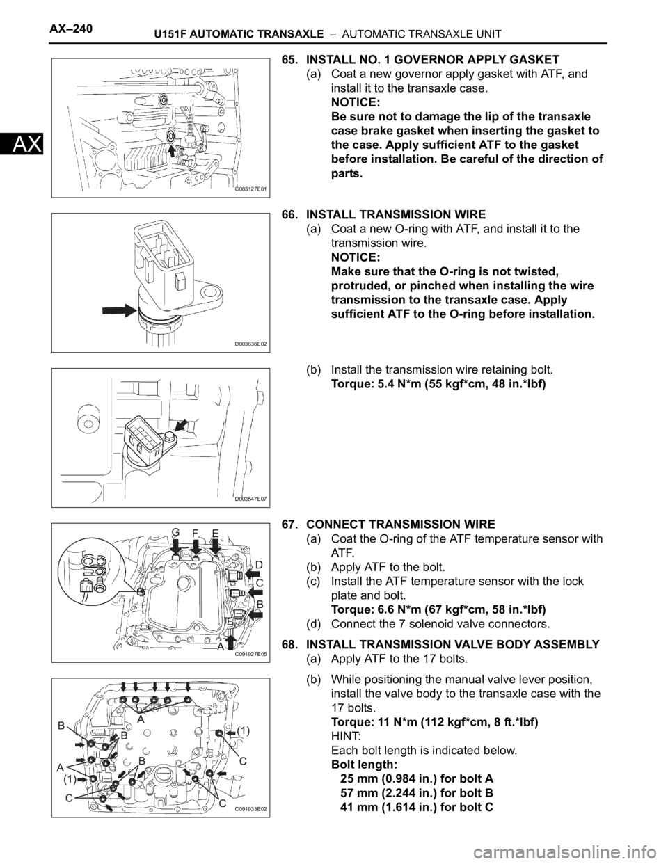
65. INSTALL NO. 1 GOVERNOR APPLY GASKET
(a) Coat a new governor apply gasket with ATF, and
install it to the transaxle case.
NOTICE:
Be sure not to damage the lip of the transaxle
case brake gasket when inserting the gasket to
the case. Apply sufficient ATF to the gasket
before installation. Be careful of the direction of
parts.
66. INSTALL TRANSMISSION WIRE
(a) Coat a new O-ring with ATF, and install it to the
transmission wire.
NOTICE:
Make sure that the O-ring is not twisted,
protruded, or pinched when installing the wire
transmission to the transaxle case. Apply
sufficient ATF to the O-ring before installation.
(b) Install the transmission wire retaining bolt.
Torque: 5.4 N*m (55 kgf*cm, 48 in.*lbf)
67. CONNECT TRANSMISSION WIRE
(a) Coat the O-ring of the ATF temperature sensor with
AT F.
(b) Apply ATF to the bolt.
(c) Install the ATF temperature sensor with the lock
plate and bolt.
Torque: 6.6 N*m (67 kgf*cm, 58 in.*lbf)
(d) Connect the 7 solenoid valve connectors.
68. INSTALL TRANSMISSION VALVE BODY ASSEMBLY
(a) Apply ATF to the 17 bolts.
(b) While positioning the manual valve lever position,
install the valve body to the transaxle case with the
17 bolts.
Torque: 11 N*m (112 kgf*cm, 8 ft.*lbf)
HINT:
Each bolt length is indicated below.
Bolt length:
25 mm (0.984 in.) for bolt A
57 mm (2.244 in.) for bolt B
41 mm (1.614 in.) for bolt C
C083127E01
D003636E02
D003547E07
C091927E05
C091933E02
Page 1245 of 2000
U241E AUTOMATIC TRANSAXLE – AUTOMATIC TRANSAXLE SYSTEMAX–21
AX
MANUAL SHIFTING TEST
1. MANUAL SHIFTING TEST
HINT:
• Through this test, it can be determined whether the
trouble occurs in the electrical circuit or if it is a
mechanical problem in the transaxle.
• If any abnormalities are found in the following test, the
problem is in the transaxle itself.
(a) Disconnect the connector of the transmission wire.
HINT:
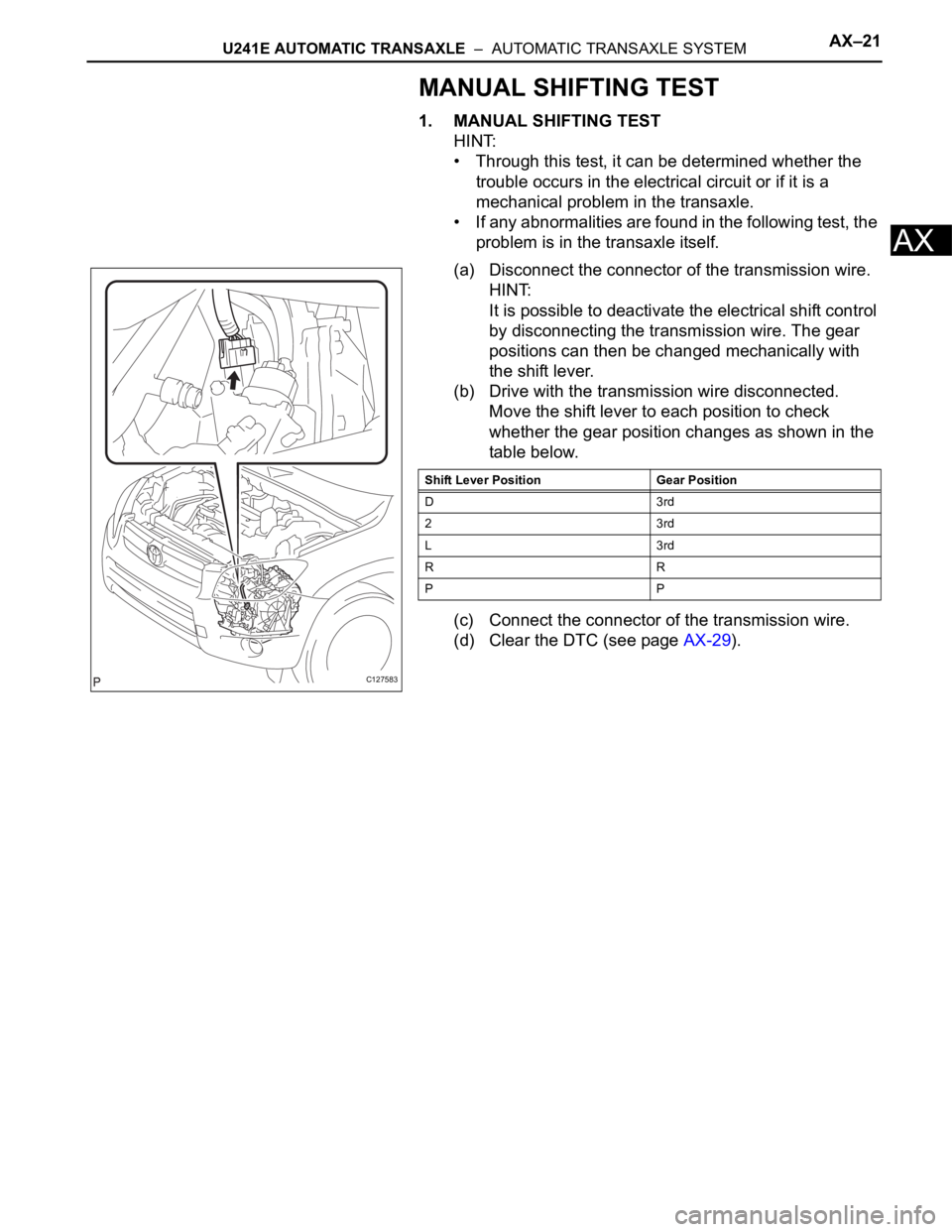
It is possible to deactivate the electrical shift control
by disconnecting the transmission wire. The gear
positions can then be changed mechanically with
the shift lever.
(b) Drive with the transmission wire disconnected.
Move the shift lever to each position to check
whether the gear position changes as shown in the
table below.
(c) Connect the connector of the transmission wire.
(d) Clear the DTC (see page AX-29).
C127583
Shift Lever Position Gear Position
D3rd
23rd
L3rd
RR
PP