radio TOYOTA RAV4 2006 Service Repair Manual
[x] Cancel search | Manufacturer: TOYOTA, Model Year: 2006, Model line: RAV4, Model: TOYOTA RAV4 2006Pages: 2000, PDF Size: 45.84 MB
Page 380 of 2000

SERVICE SPECIFICATIONS – 2AZ-FE ENGINE MECHANICALSS–13
SS
CYLINDER HEAD
ENGINE ASSEMBLY
Part Tightened N*m kgf*cm ft.*lbf
Camshaft position sensor x Cylinder head 9.0 92 80 in.*lbf
Oil pressure switch x Cylinder head 13 133 10
Radio setting condenser x Cylinder head 10 102 7
Cylinder head set bolt
Cylinder head x Cylinder
block1 st 70 714 52
2 nd Turn 90
Tu r n 9 0Tu r n 9 0
Camshaft timing gear x Camshaft 54 551 40
No. 2 camshaft timing sprocket x No. 2 camshaft 54 551 40
No. 1 and No. 2 camshaft bearing cap x Cylinder
head29.5 301 22
No. 3 camshaft bearing cap x Cylinder head 9.0 92 80 in.*lbf
Exhaust manifold x Cylinder head 37 377 27
No. 1 exhaust manifold heat insulator x Exhaust
manifold12 122 9
No. 1 and No. 2 manifold stay x Cylinder block,
Exhaust manifold44 449 32
Oil dipstick guide x Cylinder block 9.0 92 80 in.*lbf
Part Tightened N*m kgf*cm ft.*lbf
Drive plate x Crankshaft 98 1,000 72
Drive shaft bearing bracket x Cylinder block 64 653 47
No. 1 and No. 2 engine hanger x Cylinder head 38 387 28
Engine mounting insulator LH x Body 95 969 70
Engine mounting
insulator LHThrough bolt 56 571 41
Engine mounting insulator RH x Body 95 969 70
Engine mounting
insulator RH x Engine
mounting bracketNut A 95 969 70
Nut B 52 530 38
Engine mounting
insulator RR x Front
suspension
crossmemberBolt and Nut 95 969 70
Engine mounting
insulator RR x Engine
mounting bracketThough bolt 95 969 70
Engine mounting insulator FR x Front cross
member95 969 70
Engine mounting
insulator FRThough bolt 145 1,479 107
Battery carrier bracket x Body 20 204 15
Battery bracket reinforcement x Battery carrier 20 204 15
Front battery carrier x Battery bracket
reinforcement20 204 15
Air cleaner filter element x Body 5.0 51 44 in.*lbf
Radiator reservoir x Radiator support RH, Engine
mounting insulator RH5.0 51 44 in.*lbf
Battery clamp x Upper
Radiator supportFor bolt 8.5 87 75 in.*lbf
Battery clamp x Battery
clamp boltFor nut 5.0 51 44 in.*lbf
Page 430 of 2000
AIR CONDITIONING – AIR CONDITIONING CONTROL ASSEMBLY (for Manual Air Condi-
tioning System)AC–245
AC
INSTALLATION
1. INSTALL AIR VENT MODE CONTROL SWITCH
(a) Attach the 2 claws to install the mode control switch.
2. INSTALL BLOWER CONTROL SWITCH
(a) Attach the 2 claws to install the blower control
switch.
3. INSTALL AIR MIX CONTROL SWITCH
(a) Attach the 2 claws to install the air mix control
switch.
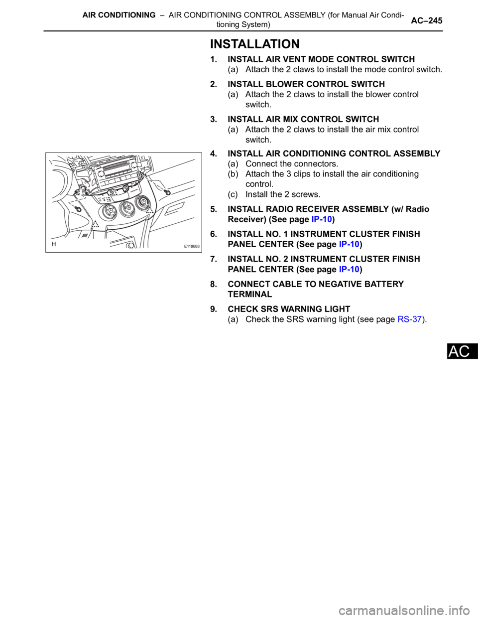
4. INSTALL AIR CONDITIONING CONTROL ASSEMBLY
(a) Connect the connectors.
(b) Attach the 3 clips to install the air conditioning
control.
(c) Install the 2 screws.
5. INSTALL RADIO RECEIVER ASSEMBLY (w/ Radio
Receiver) (See page IP-10)
6. INSTALL NO. 1 INSTRUMENT CLUSTER FINISH
PANEL CENTER (See page IP-10)
7. INSTALL NO. 2 INSTRUMENT CLUSTER FINISH
PANEL CENTER (See page IP-10)
8. CONNECT CABLE TO NEGATIVE BATTERY
TERMINAL
9. CHECK SRS WARNING LIGHT
(a) Check the SRS warning light (see page RS-37).
E118688
Page 506 of 2000
INSTRUMENT PANEL – UPPER INSTRUMENT PANELIP–5
IP
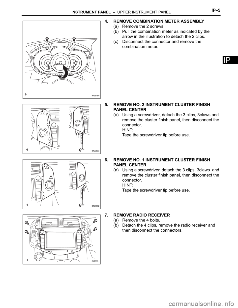
4. REMOVE COMBINATION METER ASSEMBLY
(a) Remove the 2 screws.
(b) Pull the combination meter as indicated by the
arrow in the illustration to detach the 2 clips.
(c) Disconnect the connector and remove the
combination meter.
5. REMOVE NO. 2 INSTRUMENT CLUSTER FINISH
PANEL CENTER
(a) Using a screwdriver, detach the 3 clips, 3claws and
remove the cluster finish panel, then disconnect the
connector.
HINT:
Tape the screwdriver tip before use.
6. REMOVE NO. 1 INSTRUMENT CLUSTER FINISH
PANEL CENTER
(a) Using a screwdriver, detach the 3 clips, 3claws and
remove the cluster finish panel, then disconnect the
connector.
HINT:
Tape the screwdriver tip before use.
7. REMOVE RADIO RECEIVER
(a) Remove the 4 bolts.
(b) Detach the 4 clips, remove the radio receiver and
then disconnect the connectors.
B136780
B129893
B129892
B129891
Page 603 of 2000
2AZ-FE ENGINE MECHANICAL – CYLINDER HEADEM–59
EM
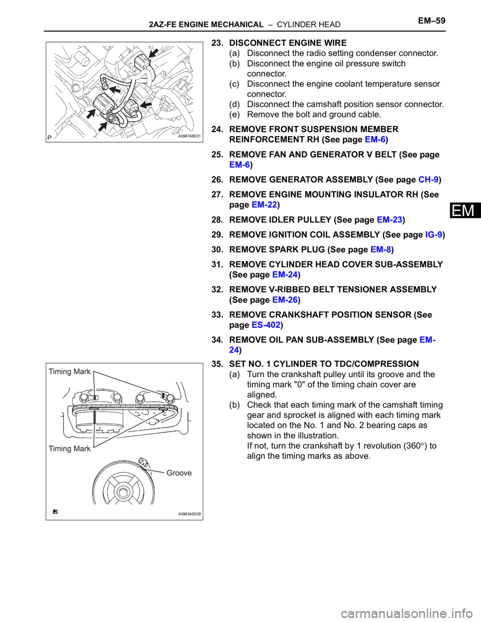
23. DISCONNECT ENGINE WIRE
(a) Disconnect the radio setting condenser connector.
(b) Disconnect the engine oil pressure switch
connector.
(c) Disconnect the engine coolant temperature sensor
connector.
(d) Disconnect the camshaft position sensor connector.
(e) Remove the bolt and ground cable.
24. REMOVE FRONT SUSPENSION MEMBER
REINFORCEMENT RH (See page EM-6)
25. REMOVE FAN AND GENERATOR V BELT (See page
EM-6)
26. REMOVE GENERATOR ASSEMBLY (See page CH-9)
27. REMOVE ENGINE MOUNTING INSULATOR RH (See
page EM-22)
28. REMOVE IDLER PULLEY (See page EM-23)
29. REMOVE IGNITION COIL ASSEMBLY (See page IG-9)
30. REMOVE SPARK PLUG (See page EM-8)
31. REMOVE CYLINDER HEAD COVER SUB-ASSEMBLY
(See page EM-24)
32. REMOVE V-RIBBED BELT TENSIONER ASSEMBLY
(See page EM-26)
33. REMOVE CRANKSHAFT POSITION SENSOR (See
page ES-402)
34. REMOVE OIL PAN SUB-ASSEMBLY (See page EM-
24)
35. SET NO. 1 CYLINDER TO TDC/COMPRESSION
(a) Turn the crankshaft pulley until its groove and the
timing mark "0" of the timing chain cover are
aligned.
(b) Check that each timing mark of the camshaft timing
gear and sprocket is aligned with each timing mark
located on the No. 1 and No. 2 bearing caps as
shown in the illustration.
If not, turn the crankshaft by 1 revolution (360
) to
align the timing marks as above.
A098748E01
A098345E09
Page 607 of 2000
2AZ-FE ENGINE MECHANICAL – CYLINDER HEADEM–63
EM
49. REMOVE CYLINDER HEAD GASKET
DISASSEMBLY
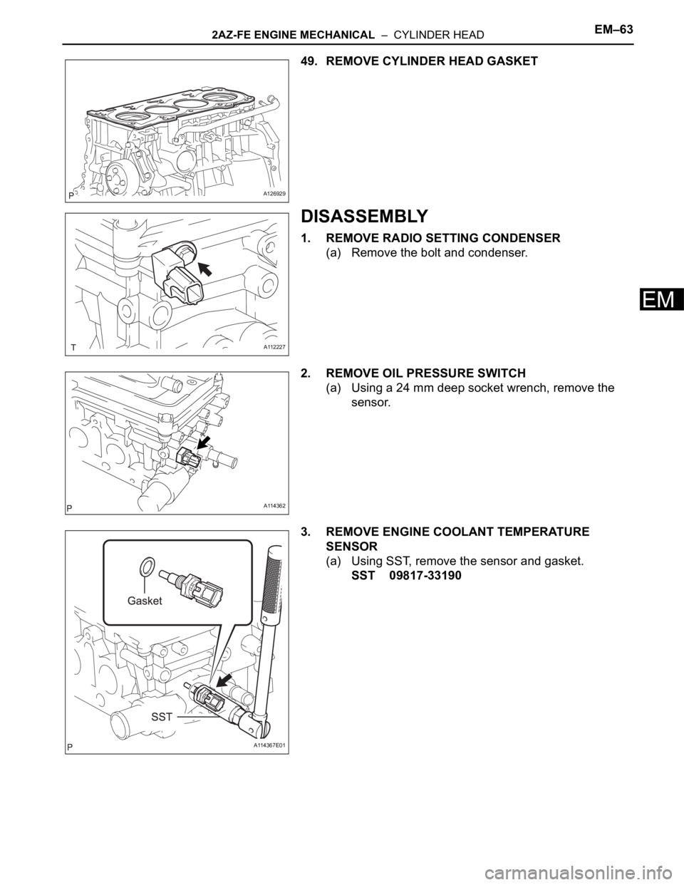
1. REMOVE RADIO SETTING CONDENSER
(a) Remove the bolt and condenser.
2. REMOVE OIL PRESSURE SWITCH
(a) Using a 24 mm deep socket wrench, remove the
sensor.
3. REMOVE ENGINE COOLANT TEMPERATURE
SENSOR
(a) Using SST, remove the sensor and gasket.
SST 09817-33190
A126929
A112227
A114362
A114367E01
Page 627 of 2000
2AZ-FE ENGINE MECHANICAL – CYLINDER HEADEM–83
EM
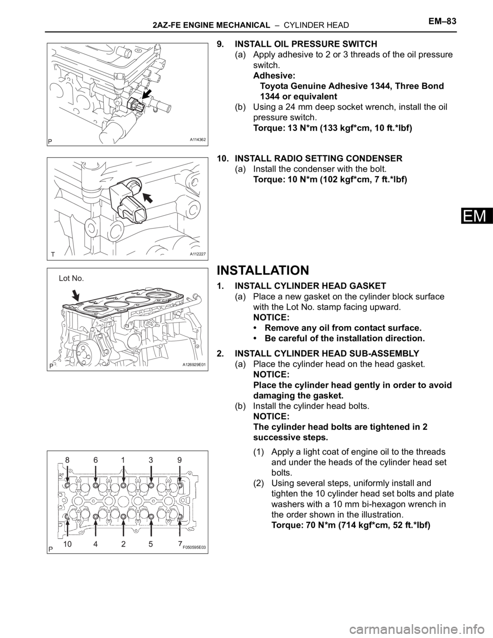
9. INSTALL OIL PRESSURE SWITCH
(a) Apply adhesive to 2 or 3 threads of the oil pressure
switch.
Adhesive:
Toyota Genuine Adhesive 1344, Three Bond
1344 or equivalent
(b) Using a 24 mm deep socket wrench, install the oil
pressure switch.
Torque: 13 N*m (133 kgf*cm, 10 ft.*lbf)
10. INSTALL RADIO SETTING CONDENSER
(a) Install the condenser with the bolt.
Torque: 10 N*m (102 kgf*cm, 7 ft.*lbf)
INSTALLATION
1. INSTALL CYLINDER HEAD GASKET
(a) Place a new gasket on the cylinder block surface
with the Lot No. stamp facing upward.
NOTICE:
• Remove any oil from contact surface.
• Be careful of the installation direction.
2. INSTALL CYLINDER HEAD SUB-ASSEMBLY
(a) Place the cylinder head on the head gasket.
NOTICE:
Place the cylinder head gently in order to avoid
damaging the gasket.
(b) Install the cylinder head bolts.
NOTICE:
The cylinder head bolts are tightened in 2
successive steps.
(1) Apply a light coat of engine oil to the threads
and under the heads of the cylinder head set
bolts.
(2) Using several steps, uniformly install and
tighten the 10 cylinder head set bolts and plate
washers with a 10 mm bi-hexagon wrench in
the order shown in the illustration.
Torque: 70 N*m (714 kgf*cm, 52 ft.*lbf)
A114362
A112227
A126929E01
F050595E03
Page 630 of 2000
EM–862AZ-FE ENGINE MECHANICAL – CYLINDER HEAD
EM
22. INSTALL ENGINE MOUNTING INSULATOR RH (See
page EM-41)
23. INSTALL RADIATOR RESERVOIR (See page EM-112)
24. INSTALL GENERATOR ASSEMBLY (See page CH-15)
25. INSTALL FAN AND GENERATOR V BELT (See page
EM-7)
26. INSTALL FRONT SUSPENSION MEMBER
REINFORCEMENT RH (See page EM-7)
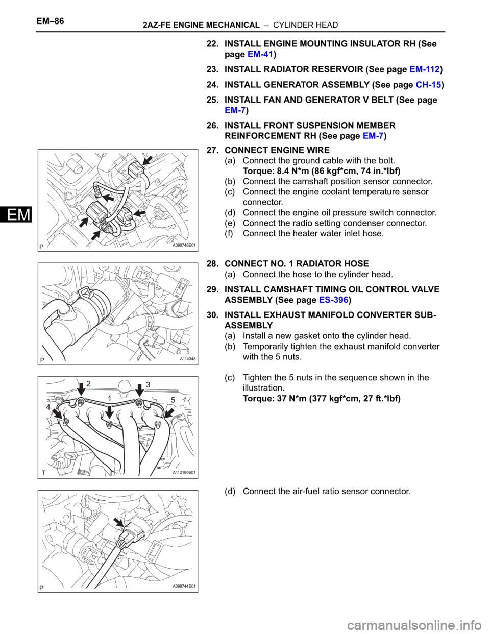
27. CONNECT ENGINE WIRE
(a) Connect the ground cable with the bolt.
Torque: 8.4 N*m (86 kgf*cm, 74 in.*lbf)
(b) Connect the camshaft position sensor connector.
(c) Connect the engine coolant temperature sensor
connector.
(d) Connect the engine oil pressure switch connector.
(e) Connect the radio setting condenser connector.
(f) Connect the heater water inlet hose.
28. CONNECT NO. 1 RADIATOR HOSE
(a) Connect the hose to the cylinder head.
29. INSTALL CAMSHAFT TIMING OIL CONTROL VALVE
ASSEMBLY (See page ES-396)
30. INSTALL EXHAUST MANIFOLD CONVERTER SUB-
ASSEMBLY
(a) Install a new gasket onto the cylinder head.
(b) Temporarily tighten the exhaust manifold converter
with the 5 nuts.
(c) Tighten the 5 nuts in the sequence shown in the
illustration.
Torque: 37 N*m (377 kgf*cm, 27 ft.*lbf)
(d) Connect the air-fuel ratio sensor connector.
A098748E01
A114348
A112190E01
A098744E01
Page 650 of 2000
2AZ-FE ENGINE MECHANICAL – ENGINE UNITEM–123
EM
DISASSEMBLY
1. REMOVE IDLER PULLEY (See page EM-23)
2. REMOVE OIL DIPSTICK
3. REMOVE OIL DIPSTICK GUIDE (See page EM-57)
4. REMOVE MANIFOLD STAY (See page EM-57)
5. REMOVE NO. 2 MANIFOLD STAY (See page EM-58)
6. REMOVE NO. 1 EXHAUST MANIFOLD HEAT
INSULATOR (See page EM-58)
7. REMOVE EXHAUST MANIFOLD CONVERTER SUB-
ASSEMBLY (See page EM-58)
8. REMOVE WATER INLET (See page CO-15)
9. REMOVE THERMOSTAT
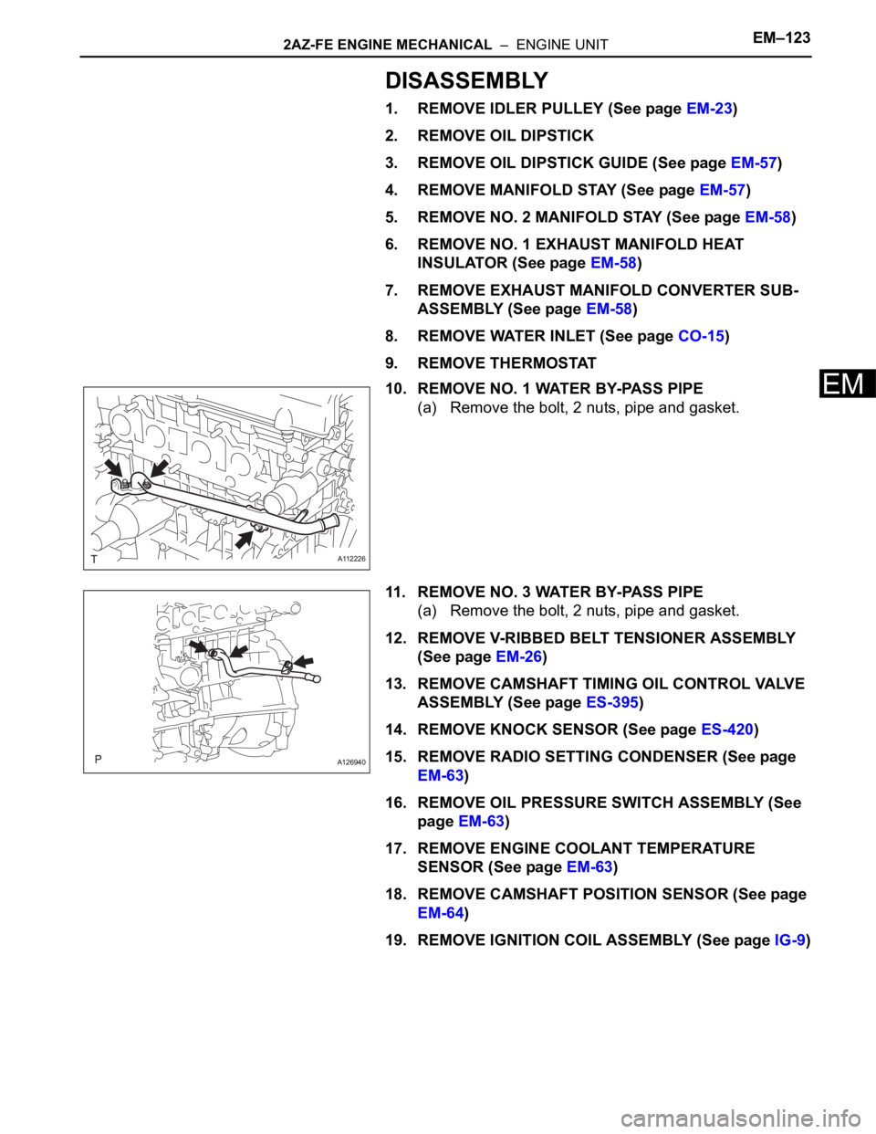
10. REMOVE NO. 1 WATER BY-PASS PIPE
(a) Remove the bolt, 2 nuts, pipe and gasket.
11. REMOVE NO. 3 WATER BY-PASS PIPE
(a) Remove the bolt, 2 nuts, pipe and gasket.
12. REMOVE V-RIBBED BELT TENSIONER ASSEMBLY
(See page EM-26)
13. REMOVE CAMSHAFT TIMING OIL CONTROL VALVE
ASSEMBLY (See page ES-395)
14. REMOVE KNOCK SENSOR (See page ES-420)
15. REMOVE RADIO SETTING CONDENSER (See page
EM-63)
16. REMOVE OIL PRESSURE SWITCH ASSEMBLY (See
page EM-63)
17. REMOVE ENGINE COOLANT TEMPERATURE
SENSOR (See page EM-63)
18. REMOVE CAMSHAFT POSITION SENSOR (See page
EM-64)
19. REMOVE IGNITION COIL ASSEMBLY (See page IG-9)
A112226
A126940
Page 1478 of 2000
TW–6TIRE AND WHEEL – TIRE PRESSURE WARNING SYSTEM
TW
SYSTEM DESCRIPTION
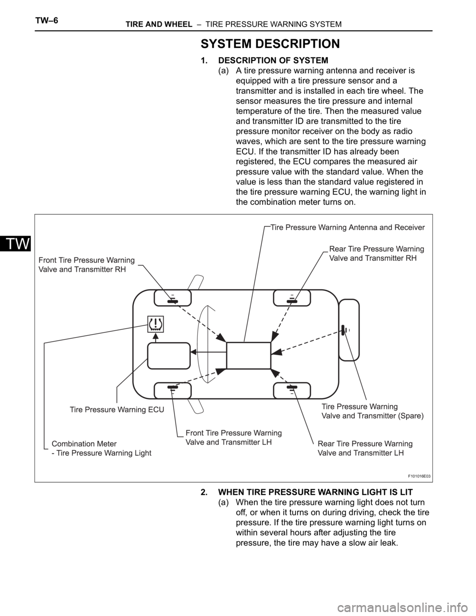
1. DESCRIPTION OF SYSTEM
(a) A tire pressure warning antenna and receiver is
equipped with a tire pressure sensor and a
transmitter and is installed in each tire wheel. The
sensor measures the tire pressure and internal
temperature of the tire. Then the measured value
and transmitter ID are transmitted to the tire
pressure monitor receiver on the body as radio
waves, which are sent to the tire pressure warning
ECU. If the transmitter ID has already been
registered, the ECU compares the measured air
pressure value with the standard value. When the
value is less than the standard value registered in
the tire pressure warning ECU, the warning light in
the combination meter turns on.
2. WHEN TIRE PRESSURE WARNING LIGHT IS LIT
(a) When the tire pressure warning light does not turn
off, or when it turns on during driving, check the tire
pressure. If the tire pressure warning light turns on
within several hours after adjusting the tire
pressure, the tire may have a slow air leak.
F101016E03
Page 1479 of 2000

TIRE AND WHEEL – TIRE PRESSURE WARNING SYSTEMTW–7
TW
(b) Under the following conditions, the system may not
function properly;
• Areas, facilities or devices that use similar radio
frequencies are located in the vicinity of the
vehicle.
• Devices using similar radio frequencies are used
in the vehicle.
• Large amounts of snow or ice are stuck to the
vehicle, especially on the wheels and around the
wheel houses.
• The battery of the transmitter is depleted.
• Tires and wheels without tire pressure warning
valves and transmitters are used.
• Snow tires and tire chains are used.
• If wheels other than the specified ones are used,
the system may not function properly because
different radio waves are transmitted from the tire
pressure warning valve and transmitter.
• Depending on the tire type, the tire pressure
warning valve and transmitter may not function
properly even though the specified wheels are
used.
• The system may not function properly if it is
initialized with tire pressures which are not the
specified values.
(c) The average life of the grommet of the tire pressure
warning antenna and receiver is approximately 5
years, at which time it must be replaced. Retighten
the valve nut if the valve is leaking air, if it is less
than 5 years old, and there is no problem with the
grommets.
(d) After removing and installing the ECU or a sensor,
output a diagnosis code and check that it is a
normal code.
3. FUNCTION OF COMPONENTS
Components Function
Tire pressure warning antenna and receiver • Combined as a single unit with a disc wheel air valve, it measures
tire pressure and temperature, and transmits an ID number for
measurement value and identification
• Battery is built into valve
Tire pressure warning antenna and receiver Receives necessary signals from tire pressure warning antenna and
receiver and transmits them to tire pressure warning ECU
Tire pressure warning ECU • Receives signal from receiver and identifies it as vehicle's own
signal.
• If measurement value is equal to or lower than specified value, it
transmits a signal so that the air pressure warning light on
combination meter turns on.
Tire pressure warning light Located in the combination meter, it informs driver of lowered tire air
pressure and system failure