radio antenna TOYOTA RAV4 2006 Service Repair Manual
[x] Cancel search | Manufacturer: TOYOTA, Model Year: 2006, Model line: RAV4, Model: TOYOTA RAV4 2006Pages: 2000, PDF Size: 45.84 MB
Page 1478 of 2000

TW–6TIRE AND WHEEL – TIRE PRESSURE WARNING SYSTEM
TW
SYSTEM DESCRIPTION
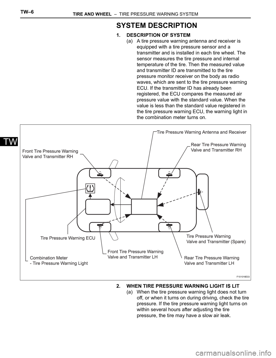
1. DESCRIPTION OF SYSTEM
(a) A tire pressure warning antenna and receiver is
equipped with a tire pressure sensor and a
transmitter and is installed in each tire wheel. The
sensor measures the tire pressure and internal
temperature of the tire. Then the measured value
and transmitter ID are transmitted to the tire
pressure monitor receiver on the body as radio
waves, which are sent to the tire pressure warning
ECU. If the transmitter ID has already been
registered, the ECU compares the measured air
pressure value with the standard value. When the
value is less than the standard value registered in
the tire pressure warning ECU, the warning light in
the combination meter turns on.
2. WHEN TIRE PRESSURE WARNING LIGHT IS LIT
(a) When the tire pressure warning light does not turn
off, or when it turns on during driving, check the tire
pressure. If the tire pressure warning light turns on
within several hours after adjusting the tire
pressure, the tire may have a slow air leak.
F101016E03
Page 1479 of 2000

TIRE AND WHEEL – TIRE PRESSURE WARNING SYSTEMTW–7
TW
(b) Under the following conditions, the system may not
function properly;
• Areas, facilities or devices that use similar radio
frequencies are located in the vicinity of the
vehicle.
• Devices using similar radio frequencies are used
in the vehicle.
• Large amounts of snow or ice are stuck to the
vehicle, especially on the wheels and around the
wheel houses.
• The battery of the transmitter is depleted.
• Tires and wheels without tire pressure warning
valves and transmitters are used.
• Snow tires and tire chains are used.
• If wheels other than the specified ones are used,
the system may not function properly because
different radio waves are transmitted from the tire
pressure warning valve and transmitter.
• Depending on the tire type, the tire pressure
warning valve and transmitter may not function
properly even though the specified wheels are
used.
• The system may not function properly if it is
initialized with tire pressures which are not the
specified values.
(c) The average life of the grommet of the tire pressure
warning antenna and receiver is approximately 5
years, at which time it must be replaced. Retighten
the valve nut if the valve is leaking air, if it is less
than 5 years old, and there is no problem with the
grommets.
(d) After removing and installing the ECU or a sensor,
output a diagnosis code and check that it is a
normal code.
3. FUNCTION OF COMPONENTS
Components Function
Tire pressure warning antenna and receiver • Combined as a single unit with a disc wheel air valve, it measures
tire pressure and temperature, and transmits an ID number for
measurement value and identification
• Battery is built into valve
Tire pressure warning antenna and receiver Receives necessary signals from tire pressure warning antenna and
receiver and transmits them to tire pressure warning ECU
Tire pressure warning ECU • Receives signal from receiver and identifies it as vehicle's own
signal.
• If measurement value is equal to or lower than specified value, it
transmits a signal so that the air pressure warning light on
combination meter turns on.
Tire pressure warning light Located in the combination meter, it informs driver of lowered tire air
pressure and system failure
Page 1503 of 2000

TIRE AND WHEEL – TIRE PRESSURE WARNING SYSTEMTW–31
TW
DESCRIPTION
The tire pressure warning valve and transmitter constantly sends radio waves to the tire pressure warning
ECU.
Under the following conditions, the tire pressure warning antenna and receiver is unable to receive the
signals from the tire pressure warning valve and transmitter, and a DTC is output.
• Areas, facilities, or devices that use similar radio frequencies are located in the vicinity of the vehicle.
• Devices using similar radio frequencies are used in the vehicle.
DTCs C2121/21 to C2125/25 can only be deleted by the tester. DTCs C2181/81 to C2185/85 can be
deleted when the transmitter sends a forced transmission signal or the test mode ends. DTCs C2181/81
to C2185/85 are output only in the test mode.
HINT:
When no signals are received for 60 minutes or more, a DTC is output.
It is necessary to perform the procedure to identify the tire pressure warning valve and transmitter that is
malfunctioning because it cannot be identified by the output DTC.
DTC C2121/21 No Signal from Transmitter ID1 in Main Mode
DTC C2122/22 No Signal from Transmitter ID2 in Main Mode
DTC C2123/23 No Signal from Transmitter ID3 in Main Mode
DTC C2124/24 No Signal from Transmitter ID4 in Main Mode
DTC C2125/25 No Signal from Transmitter ID5 in Main Mode
DTC C2181/81 Transmitter ID1 not Received (Test Mode DTC)
DTC C2182/82 Transmitter ID2 not Received (Test Mode DTC)
DTC C2183/83 Transmitter ID3 not Received (Test Mode DTC)
DTC C2184/84 Transmitter ID4 not Received (Test Mode DTC)
DTC C2185/85 Transmitter ID5 not Received (Test Mode DTC)
DTC No. DTC Detection Condition Trouble Area
C2121/21
C2122/22
C2123/23
C2124/24
C2125/25These DTCs are detected when no signals
are received for 51 minutes or more, after a
vehicle speed of 5 mph (8 km/h) or more is
detected and no signals are received for 12
minutes or more• Tire pressure warning valve and
transmitter
• Tire pressure warning antenna and
receiver
• Tire pressure warning ECU
• Wire harness
C2181/81
C2182/82
C2183/83
C2184/84
C2185/85Malfunction in transmission / reception circuit • Tire pressure warning valve and
transmitter
• Tire pressure warning antenna and
receiver
• Tire pressure warning ECU
• Wire harness