rese ignition TOYOTA RAV4 2006 Service Repair Manual
[x] Cancel search | Manufacturer: TOYOTA, Model Year: 2006, Model line: RAV4, Model: TOYOTA RAV4 2006Pages: 2000, PDF Size: 45.84 MB
Page 66 of 2000

ENGINE - 2AZ-FE ENGINE
01MEG02Y
Valve Timing : Intake Valve Opening Angle
: Exhaust Valve Opening Angle
VVT-i Operation
Range
VVT-i Operation
RangeTDC
3
3
43
65
25
45
BDCEG-3
Engine Specifications
No. of Cyls. & Arrangement4-cylinder, In-line
Valve Mechanism16-valve DOHC, Chain Drive (with VVT-i)
Combustion ChamberPentroof Type
ManifoldsCross-flow
Fuel SystemSFI
Ignition SystemDIS
Displacement cm3 (cu. in.)2362 (144.1)
Bore x Stroke mm (in.)88.5 x 96.0 (3.48 x 3.78)
Compression Ratio9.8 : 1
Max. Output*1(SAE-NET)124 kW @ 6000 rpm (166 HP @ 6000 rpm)
Max. Torque*1(SAE-NET)224 N.m @ 4000 rpm (165 ft-lbf @ 4000 rpm)
IntakeOpen3 - 43 BTDC
Valve Timing
IntakeClose65 - 25 ABDCVa l v e T i m i n g
ExhaustOpen45 BBDCExhaustClose3 ATDC
Firing Order1 - 3 - 4 - 2
Research Octane Number91 or higher
Octane Rating87 or higher
Oil GradeILSAC
Tailpipe Emission RegulationULEV-II, SFTP
Evaporative Emission RegulationLEV-II, ORVR
Engine Service Mass*2 (Reference) kg (lb)138 (304.2)
*1: Maximum output and torque rating is determined by revised SAE J1349 standard.
*
2: Weight shows the figure with oil and water fully filled.
Page 383 of 2000

SERVICE SPECIFICATIONS – 2GR-FE ENGINE MECHANICALSS–21
SS
TORQUE SPECIFICATIONS
Part Tightened N*m kgf*cm ft.*lbf
Front suspension member reinforcement RH x Front
crossmember95 969 70
Front suspension member reinforcement RH x Front
suspension crossmember95 969 70
Radiator reservoir tank x Bract 5.0 51 44 in.*lbf
Engine coolant temperature sensor x Water outlet 20 204 14
Engine oil pressure sensor x Oil pan 21 214 15
No. 1 front engine mounting bracket LH x Timing chain
cover54 551 40
No. 2 idler pulley x Timing chain cover 43 438 32
No. 2 timing gear cover x Timing chain cover 6.0 61 53 in.*lbf
V-ribbed belt tensioner x Timing chain cover 43 438 32
V-ribbed belt tensioner x Cylinder block 43 438 32
Drive shaft bearing bracket x Cylinder block 64 653 47
Exhaust manifold LH x Cylinder head 21 214 15
No. 2 exhaust heat insulator x Exhaust manifold 8.5 87 75 in.*lbf
No. 2 manifold stay x Exhaust manifold 34 347 25
No. 2 manifold stay x Cylinder block 34 347 25
No. 1 oil dipstick guide x Cylinder block 21 214 15
No. 2 oil dipstick guide x Cylinder head 21 214 15
Exhaust manifold RH x Cylinder head 21 214 15
Intake manifold x Cylinder head 21 214 15
No. 2 engine mounting stay RH x Intake manifold 21 214 15
No. 2 engine mounting stay RH x Timing chain cover 21 214 15
Ignition coil x Cylinder head cover 10 102 7
Intake air surge tank x
Intake manifold5 mm hexagon wrench 18 184 13
for Bolt 21 214 15
for Nut 16 163 12
Vacuum hose clamp x Intake air surge tank 5.4 55 48 in.*lbf
Drive plate and ring gear x Crankshaft 178 1,815 132
Engine mounting bracket RR x Engine mounting
insulator RR95 969 70
Engine mounting bracket FR x Engine mounting
insulator FR145 1,479 107
Engine mounting bracket LH x Engine mounting
insulator LH56 571 41
Engine mounting insulator
RH x Front No. 1 engine
mounting bracketfor Bolt and nut A 95 969 70
for Nut B 52 530 38
Front crossmember x
Bodyfor Bolt A 96 979 71
Front suspension member
x Bodyfor Bolt B 145 1,478 107
Front suspension member
brace rear x Bodyfor Bolt C 145 1,478 107
for Bolt D 93 948 69
Air cleaner case x Engine mounting insulator LH 5.0 51 44 in.*lbf
Battery bracket reinforcement x Body 19 194 14
Front battery bracket x Body 19 194 14
Front battery bracket x Battery bracket reinforcement 19 194 14
Battery clamp x Body 5.0 51 44 in.*lbf
Page 885 of 2000

2AZ-FE IGNITION – IGNITION SYSTEMIG–5
IG
ON-VEHICLE INSPECTION
1. CHECK IGNITION COIL ASSEMBLY AND PERFORM
SPARK TEST
NOTICE:
In this section, the terms "cold" and "hot" refer to
the temperature of the coils. "Cold" means
approximately -10 to 50
C (14 to 122F). "Hot" means
approximately 50 to 100
C (122 to 212F).
(a) Check the DTCs.
NOTICE:
If a DTC is present, perform troubleshooting in
accordance with the procedure for that DTC.
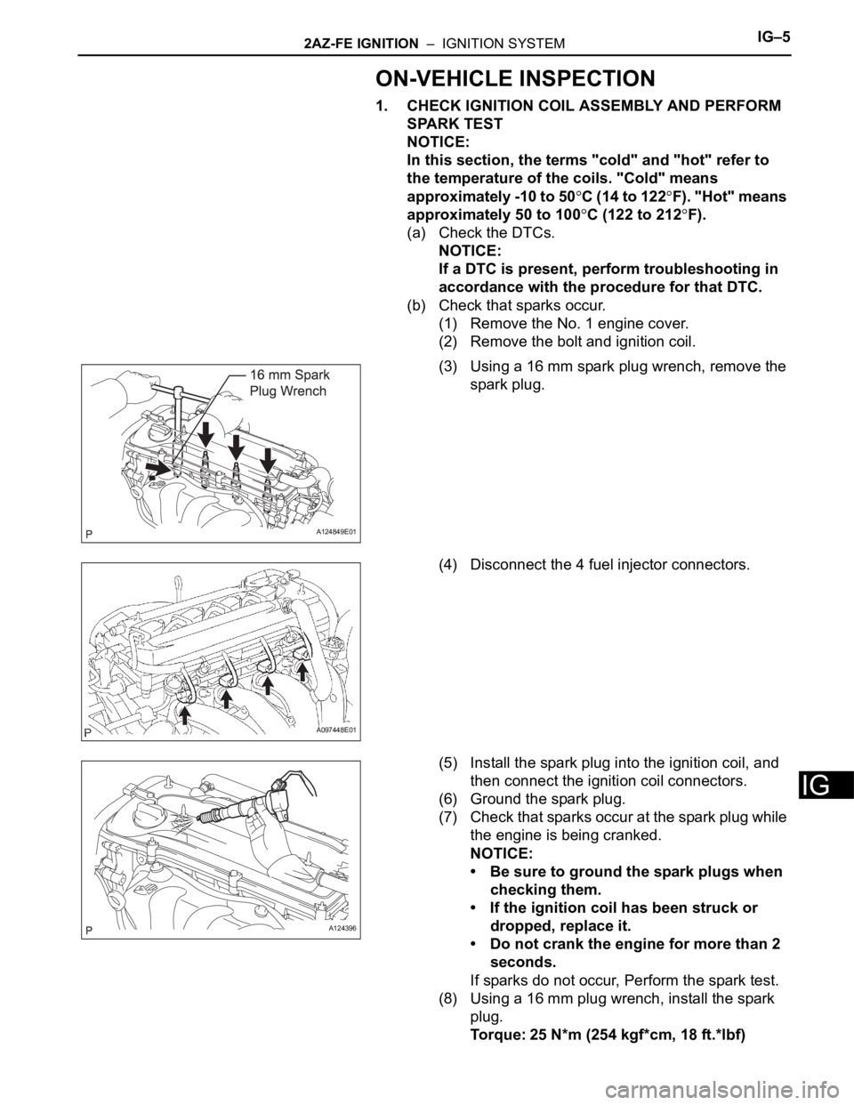
(b) Check that sparks occur.
(1) Remove the No. 1 engine cover.
(2) Remove the bolt and ignition coil.
(3) Using a 16 mm spark plug wrench, remove the
spark plug.
(4) Disconnect the 4 fuel injector connectors.
(5) Install the spark plug into the ignition coil, and
then connect the ignition coil connectors.
(6) Ground the spark plug.
(7) Check that sparks occur at the spark plug while
the engine is being cranked.
NOTICE:
• Be sure to ground the spark plugs when
checking them.
• If the ignition coil has been struck or
dropped, replace it.
• Do not crank the engine for more than 2
seconds.
If sparks do not occur, Perform the spark test.
(8) Using a 16 mm plug wrench, install the spark
plug.
Torque: 25 N*m (254 kgf*cm, 18 ft.*lbf)
A124849E01
A097448E01
A124396
Page 895 of 2000

2GR-FE IGNITION – IGNITION SYSTEMIG–5
IG
ON-VEHICLE INSPECTION
1. CHECK IGNITION COIL ASSEMBLY AND PERFORM
SPARK TEST
NOTICE:
In this section, the terms "Cold" and "Hot" refer to
the temperature of the sensor. "Cold" means
approximately -10 to 50
C (14 to 122F). "Hot" means
approximately 50 to 100
C (122 to 212F).
(a) Check the DTCs.
NOTICE:
If a DTC is present, perform troubleshooting in
accordance with the procedure for that DTC.
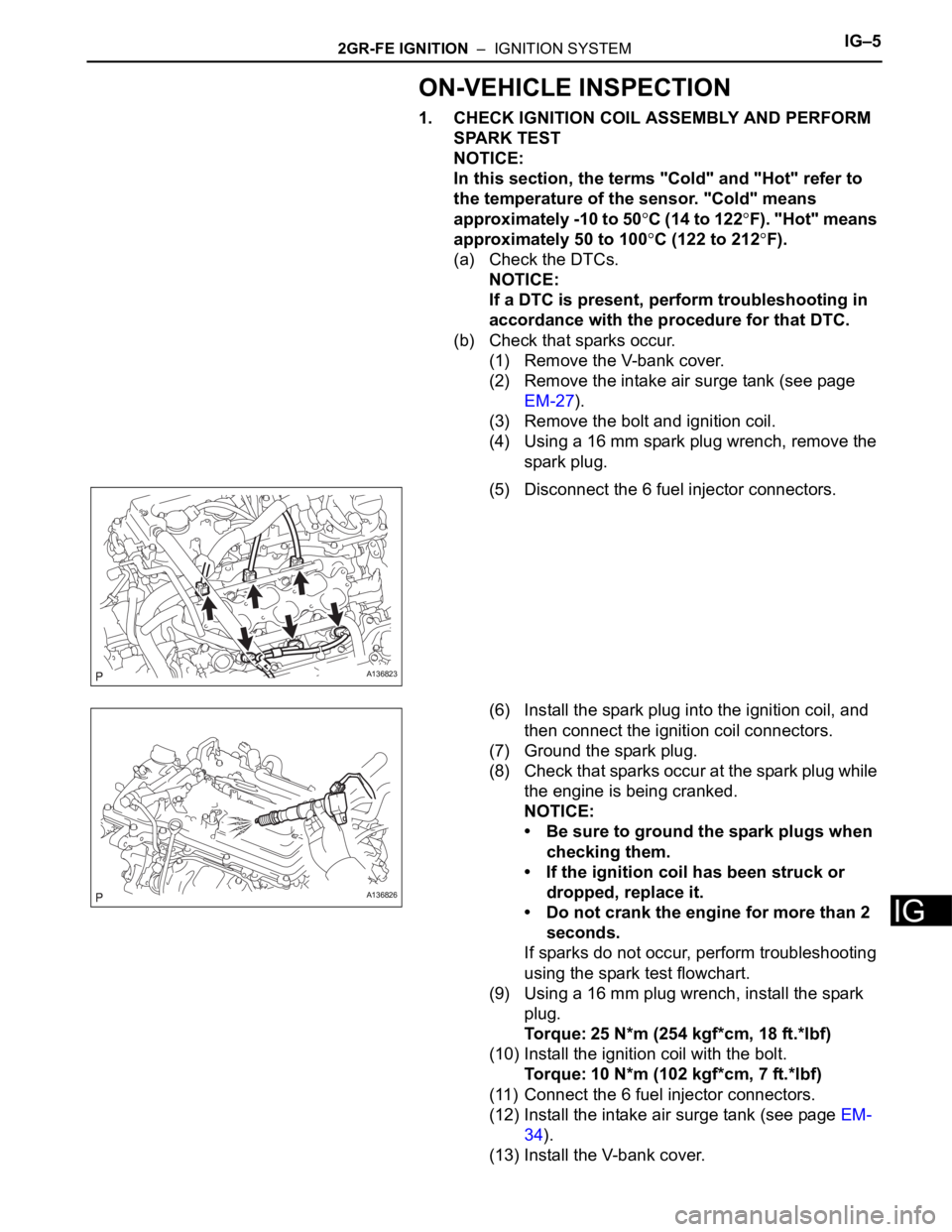
(b) Check that sparks occur.
(1) Remove the V-bank cover.
(2) Remove the intake air surge tank (see page
EM-27).
(3) Remove the bolt and ignition coil.
(4) Using a 16 mm spark plug wrench, remove the
spark plug.
(5) Disconnect the 6 fuel injector connectors.
(6) Install the spark plug into the ignition coil, and
then connect the ignition coil connectors.
(7) Ground the spark plug.
(8) Check that sparks occur at the spark plug while
the engine is being cranked.
NOTICE:
• Be sure to ground the spark plugs when
checking them.
• If the ignition coil has been struck or
dropped, replace it.
• Do not crank the engine for more than 2
seconds.
If sparks do not occur, perform troubleshooting
using the spark test flowchart.
(9) Using a 16 mm plug wrench, install the spark
plug.
Torque: 25 N*m (254 kgf*cm, 18 ft.*lbf)
(10) Install the ignition coil with the bolt.
Torque: 10 N*m (102 kgf*cm, 7 ft.*lbf)
(11) Connect the 6 fuel injector connectors.
(12) Install the intake air surge tank (see page EM-
34).
(13) Install the V-bank cover.
A136823
A136826
Page 956 of 2000

AX–22U140F AUTOMATIC TRANSAXLE – AUTOMATIC TRANSAXLE SYSTEM
AX
INITIALIZATION
1. RESET MEMORY
NOTICE:
• Perform the RESET MEMORY procedures (A/T
initialization) when replacing the automatic
transaxle assembly, engine assembly or ECM.
• RESET MEMORY can be performed only with the
intelligent tester.
HINT:
The ECM memorizes the vehicle conditions when the
ECT controls the automatic transaxle assembly and
engine assembly. Therefore, when the automatic
transaxle assembly, engine assembly, or ECM has been
replaced, it is necessary to reset the memory so that the
ECM can memorize the new information.
The reset procedures are as follows.
(a) Turn the ignition switch OFF.
(b) Connect the intelligent tester to the CAN VIM. Then
connect the CAN VIM to the DLC3.
(c) Turn the ignition switch ON and turn the tester ON.
(d) Enter the following menus: DIAGNOSIS /
ENHANCED OBD II.
(e) Perform the reset memory procedures from the
Engine menu.
CAUTION:
After performing the RESET MEMORY
procedures, be sure to perform the ROAD TEST
(see page AX-12) as described earlier.
HINT:
The ECM learns through the ROAD TEST.
Page 1039 of 2000

U151E AUTOMATIC TRANSAXLE – AUTOMATIC TRANSAXLE SYSTEMAX–23
AX
INITIALIZATION
1. RESET MEMORY
NOTICE:
• Perform the RESET MEMORY procedures (A/T
initialization) when replacing the automatic
transaxle assembly, engine assembly or ECM.
• RESET MEMORY can be performed only with the
intelligent tester.
HINT:
The ECM memorizes the vehicle conditions when the
ECT controls the automatic transaxle assembly and
engine assembly. Therefore, when the automatic
transaxle assembly, engine assembly, or ECM has been
replaced, it is necessary to reset the memory so that the
ECM can memorize the new information.
The reset procedures are as follows.
(a) Turn the ignition switch OFF.
(b) Connect the intelligent tester to the CAN VIM. Then
connect the CAN VIM to the DLC3.
(c) Turn the ignition switch ON and turn the tester ON.
(d) Enter the following menus: DIAGNOSIS /
ENHANCED OBD II.
(e) Perform the reset memory procedures from the
Engine menu.
CAUTION:
After performing the RESET MEMORY
procedures, be sure to perform the ROAD TEST
(see page AX-13) as described earlier.
HINT:
The ECM learns through the ROAD TEST.
Page 1142 of 2000

U151F AUTOMATIC TRANSAXLE – AUTOMATIC TRANSAXLE SYSTEMAX–23
AX
INITIALIZATION
1. RESET MEMORY
NOTICE:
• Perform the RESET MEMORY procedures (A/T
initialization) when replacing the automatic
transaxle assembly, engine assembly or ECM.
• RESET MEMORY can be performed only with the
intelligent tester.
HINT:
The ECM memorizes the vehicle conditions when the
ECT controls the automatic transaxle assembly and
engine assembly. Therefore, when the automatic
transaxle assembly, engine assembly, or ECM has been
replaced, it is necessary to reset the memory so that the
ECM can memorize the new information.
The reset procedures are as follows.
(a) Turn the ignition switch OFF.
(b) Connect the intelligent tester to the CAN VIM. Then
connect the CAN VIM to the DLC3.
(c) Turn the ignition switch ON and turn the tester ON.
(d) Enter the following menus: DIAGNOSIS /
ENHANCED OBD II.
(e) Perform the reset memory procedures from the
Engine menu.
CAUTION:
After performing the RESET MEMORY
procedures, be sure to perform the ROAD TEST
(see page AX-13) as described earlier.
HINT:
The ECM learns through the ROAD TEST.
Page 1246 of 2000

AX–22U241E AUTOMATIC TRANSAXLE – AUTOMATIC TRANSAXLE SYSTEM
AX
INITIALIZATION
1. RESET MEMORY
NOTICE:
• Perform the RESET MEMORY procedures (A/T
initialization) when replacing the automatic
transaxle assembly, engine assembly or ECM.
• RESET MEMORY can be performed only with the
intelligent tester.
HINT:
The ECM memorizes the vehicle conditions when the
ECT controls the automatic transaxle assembly and
engine assembly. Therefore, when the automatic
transaxle assembly, engine assembly, or ECM has been
replaced, it is necessary to reset the memory so that the
ECM can memorize the new information.
The reset procedures are as follows.
(a) Turn the ignition switch OFF.
(b) Connect the intelligent tester to the CAN VIM. Then
connect the CAN VIM to the DLC3.
(c) Turn the ignition switch ON and turn the tester ON.
(d) Enter the following menus: DIAGNOSIS /
ENHANCED OBD II.
(e) Perform the reset memory procedures from the
Engine menu.
CAUTION:
After performing the RESET MEMORY
procedures, be sure to perform the ROAD TEST
(see page AX-12) as described earlier.
HINT:
The ECM learns through the ROAD TEST.
Page 1522 of 2000

BRAKE CONTROL – VEHICLE STABILITY CONTROL SYSTEMBC–19
BC
4. FAIL SAFE FUNCTION
(a) When a failure occurs in the ABS with BA, TRC and
VSC systems, the ABS and VSC warning lights
illuminate, the slip indicator light comes on*1 or
remains off*2, and the operations of those systems
are prohibited. In addition to this, when a failure
which disables the EBD operation occurs, the brake
warning light comes on and its operation is
prohibited.
HINT:
*1: for 2WD
*2: for 4WD
(b) If control is prohibited due to a malfunction during
operation, control is disabled gradually to avoid
sudden vehicle instability.
5. INITIAL CHECK
(a) When the vehicle speed first reaches approximately
6 km/h (4 mph) or more after the ignition switch is
turned ON, each solenoid valve and the motor of the
ABS and TRACTION actuator are sequentially
activated to perform electrical checks. During the
initial check, the operating sound of the solenoid
valve and motor can be heard from the engine
compartment, but this does not indicate a
malfunction.
6. SERVICE MODE
(a) VSC operation can be disabled by operating the
intelligent tester.
HINT:
Refer to the intelligent tester operator's manual for
further details.
7. FUNCTION OF COMPONENTS
Components Functions
Speed Sensor
(Semiconductor Type)Detects the wheel speed and sends the signal to skid
control ECU
Skid Control ECU
(Housed in ABS and TRACTION Actuator)• Processes the signals from each sensor to control the
ABS, BA, TRC, and VSC
• Sends and receives control signals to and from the
ECM, yaw rate and deceleration sensor, steering
sensor, etc. via CAN communication.
ABS and TRACTION Actuator • Consists of the master cylinder cut solenoid valve,
holding solenoid valve, pressure reduction solenoid
valve, pump motor, and reservoir, and adjusts the brake
fluid pressure applied to each wheel cylinder
• Houses the skid control ECU
Solenoid Relay • Supplies power to each solenoid
• Housed in the skid control ECU
Motor Relay (VSC MTR Relay) • Supplies power to the pump motor
• Installed in engine room No. 1 relay block
Fail-safe Relay (VSC FAIL Relay) • Cuts off power to the motor when the pump motor circuit
malfunctions
• Installed in engine room No. 1 relay block
Page 1529 of 2000

BC–26BRAKE CONTROL – VEHICLE STABILITY CONTROL SYSTEM
BC
CALIBRATION
1. DESCRIPTION
(a) After replacing components relating to the VSC or
performing "Front wheel alignment adjustment",
clear and read the sensor calibration data.
(b) Follow the chart to perform calibration.
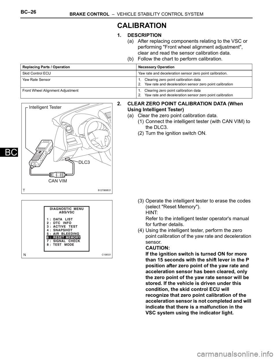
2. CLEAR ZERO POINT CALIBRATION DATA (When
Using Intelligent Tester)
(a) Clear the zero point calibration data.
(1) Connect the intelligent tester (with CAN VIM) to
the DLC3.
(2) Turn the ignition switch ON.
(3) Operate the intelligent tester to erase the codes
(select "Reset Memory").
HINT:
Refer to the intelligent tester operator's manual
for further details.
(4) Using the intelligent tester, perform the zero
point calibration of the yaw rate and deceleration
sensor.
CAUTION:
If the ignition switch is turned ON for more
than 15 seconds with the shift lever in the P
position after zero point of the yaw rate and
acceleration sensor has been cleared, only
the zero point of the yaw rate sensor will be
stored. If the vehicle is driven under this
condition, the skid control ECU will
recognize that zero point calibration of the
acceleration sensor is not completed and will
indicate that there is a malfunction in the
VSC system using the indicator light.
Replacing Parts / Operation Necessary Operation
Skid Control ECU Yaw rate and deceleration sensor zero point calibration.
Yaw Rate Sensor 1. Clearing zero point calibration data
2. Yaw rate and deceleration sensor zero point calibration
Front Wheel Alignment Adjustment 1. Clearing zero point calibration data
2. Yaw rate and deceleration sensor zero point calibration
B127989E01
C106531