rese ignition TOYOTA RAV4 2006 Service User Guide
[x] Cancel search | Manufacturer: TOYOTA, Model Year: 2006, Model line: RAV4, Model: TOYOTA RAV4 2006Pages: 2000, PDF Size: 45.84 MB
Page 1620 of 2000

PS–20POWER STEERING – ELECTRONIC POWER STEERING SYSTEM
PS
HINT:
: Warning light comes on
X: Warning light turns off (normal reset)
U0105/41 Lost Communication
with Fuel Injector
Control Module- CAN
communication
system
- ECMIgnition switch ON
again or after normal
confirmationX PS-34
U0121/42 Lost Communication
with Anti-Lock Brake
System (ABS)
Control Module- CAN
communication
system
- Skid control ECUIgnition switch ON
again or after normal
confirmation
PS-34 DTC No. Detection Item Trouble Area Normal Function
Return ConditionP/S Warning Light See page
Page 1699 of 2000
RS–50SUPPLEMENTAL RESTRAINT SYSTEM – AIRBAG SYSTEM
RS
DTC CHECK / CLEAR
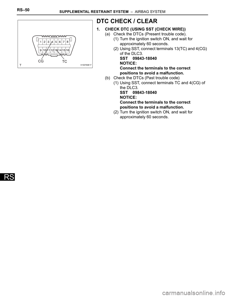
1. CHECK DTC (USING SST (CHECK WIRE))
(a) Check the DTCs (Present trouble code).
(1) Turn the ignition switch ON, and wait for
approximately 60 seconds.
(2) Using SST, connect terminals 13(TC) and 4(CG)
of the DLC3.
SST 09843-18040
NOTICE:
Connect the terminals to the correct
positions to avoid a malfunction.
(b) Check the DTCs (Past trouble code)
(1) Using SST, connect terminals TC and 4(CG) of
the DLC3.
SST 09843-18040
NOTICE:
Connect the terminals to the correct
positions to avoid a malfunction.
(2) Turn the ignition switch ON, and wait for
approximately 60 seconds.
H100769E17
Page 1702 of 2000

SUPPLEMENTAL RESTRAINT SYSTEM – AIRBAG SYSTEMRS–53
RS
3. CHECK DTC (USING INTELLIGENT TESTER)
(a) Connect the intelligent tester (with CAN VIM) to the
DLC3.
(b) Turn the ignition switch ON.
(c) Check the DTCs by following the prompts on the
tester screen.
HINT:
Refer to the intelligent tester operator's manual for
further details.
4. CLEAR DTC (USING INTELLIGENT TESTER)
(a) Connect the intelligent tester (with CAN VIM) to the
DLC3.
(b) Turn the ignition switch ON.
(c) Clear the DTCs by following the prompts on the
tester screen.
HINT:
Refer to the intelligent tester operator's manual for
further details.
CHECK MODE PROCEDURE
1. CHECK MODE (SIGNAL CHECK)
(a) Connect the intelligent tester (with CAN VIM) to the
DLC3.
(b) Turn the ignition switch ON.
(c) Select the "SIGNAL CHECK", and continue
checking with the intelligent tester.
NOTICE:
Select the "SIGNAL CHECK" from the "DTC
CHECK" screen displayed on the intelligent
tester to clear the output DTCs (both present
and past).
HINT:
• Check mode is more sensitive to malfunctions
than normal mode.
• If the normal system code is output in normal
mode even when a sensor signal malfunction is
suspected, perform the inspection in check
mode.
B127989E01
B127989E01
Page 1780 of 2000

ENGINE IMMOBILISER – ENGINE IMMOBILISER SYSTEMEI–9
EI
3. REGISTRATION OF ADDITIONAL KEY (PROCEDURE
"A")
HINT:
• A maximum of 5 master key codes and 3 sub-key
codes can be registered.
• Additional key code registration mode ends if each
step is not completed within the specified time.
• When proceeding to the next step while the timer is
running, the timer is reset and begins the countdown
for the next step.
• When the ignition key cylinder or the ignition key
cylinder set is replaced, remove the transmitter
module from the original master key. Then install this
transmitter module to a new key and use the new key
as the master key. If necessary, use this master key to
register other keys.
NOTICE:
When the ignition key cylinder has been replaced,
locking and unlocking doors are possible with the
new master key once the transmitter module from
the original master key has been transferred to it.
However, the new master key will not be able to lock
and unlock doors through the door key cylinder.
Keep the original master key. If the new master key's
transmitter module battery fails, the original master
key can be used to lock and unlock doors through
the door key cylinder.
(a) Additional key code registration
Condition:
At least one key code must be registered in the
transponder key ECU.
ProcedureTime
(Operation completion time)Security Indicator Light Condition
1. START -BLINKING
HINT:
Until first key is inserted
2. Insert previously registered master key into
ignition key cylinder, turn ignition switch to ON
position, and turn intelligent tester on
-OFF
3. Select the following items on the tester:
(1) IMMOBILISER
(2) ID UTILITY
(3) IMMOB CODE REGON
4. Remove master key and then push NEXT
button on tester. Immediately after above
operation, insert previously registered master
key into ignition key cylinder, turn ignition
switch to ON position, and then push NEXT
button on tester.Within 120 seconds BLINKING
ON
5. Remove master key and then push NEXT
button on testerWithin 20 seconds
HINT:
After the tester instruction.ON
6. Insert key to be registered into ignition key
cylinderWithin 10 seconds. BLINKING
Page 1936 of 2000

ES–482AZ-FE ENGINE CONTROL SYSTEM – SFI SYSTEM
ES
PURGE DENSITY Learning value of purge density:
Min.: -50, Max.: 350-40 to 10: Idling -
EVAP PURGE FLOWRatio of evaporative purge flow to
intake air volume:
Min.: 0 %, Max.: 102.4 %0 to 10 %: Idling -
EVAP PURGE VSVEVAP (PURGE) VSV control duty:
Min.: 0 %, Max.: 100 %10 to 50 %: Idling Order signal from ECM
VAPOR PRES PUMPVapor pressure:
Min.: 33.853 kPa, Max.: 125.596
kPaApproximately 100 kPa: Ignition
switch ONEVAP system pressure monitored
by canister pressure sensor
VAPOR PRES CALCVapor pressure (calculated):
Min.: -5.632 kPa, Max.: 715.264
kPaApproximately 100 kPa: Ignition
switch ONEVAP system pressure monitored
by canister pressure sensor
KNOCK CRRT VALKnock correction learning value:
Min: -64
CA, Max.: 1,984CA0 to 20
CA: Driving at 70 km/h
(44 mph)Service data
KNOCK FB VALKnock feedback value:
Min: -64
CA, Max.: 1,984CA-20 to 0
CA: Driving at 70 km/h
(44 mph)Service data
CLUTCHClutch current:
Min.: 0 A, Max.: 2.49 A--
EVAP VAPOR PRESEVAP vapor pressure:
Min.: 0 kPa, Max.: 327.675 kPaApproximately 100 kPa: Ignition
switch ONEVAP system pressure monitored
by canister pressure sensor
ACCEL POS #1Absolute Accelerator Pedal
Position (APP) No. 1:
Min.: 0 %, Max.: 100 %10 to 22 %: Accelerator pedal
released
52 to 90 %: Accelerator pedal
fully depressedRead value with ignition switch ON
(Do not start engine)
ACCEL POS #2Absolute APP No. 2:
Min.: 0 %, Max.: 100 %24 to 40 %: Accelerator pedal
released
68 to 100 %: Accelerator pedal
fully depressedRead value with ignition switch ON
(Do not start engine)
ACCEL POS #1APP sensor No. 1 voltage:
Min.: 0 V, Max.: 4.98 V- ETCS freeze data
ACCEL POS #2APP sensor No. 2 voltage:
Min.: 0 V, Max.: 4.98 V- ETCS freeze data
ACCEL POS #1APP sensor No. 1 voltage:
Min.: 0 V, Max.: 5 V0.5 to 1.1 V: Accelerator pedal
released
2.6 to 4.5 V: Accelerator pedal
fully depressedRead value with ignition switch ON
(Do not start engine)
ACCEL POS #2APP sensor No. 2 voltage:
Min.: 0 V, Max.: 5 V1.2 to 2.0 V: Accelerator pedal
released
3.4 to 5.0 V: Accelerator pedal
fully depressedRead value with ignition switch ON
(Do not start engine)
ACCEL IDL POSWhether or not accelerator pedal
position sensor detecting idle:
ON or OFFON: Idling -
THRTL LEARN VALThrottle valve fully closed
(learned value):
Min.: 0 V, Max.: 5 V0.4 to 0.8 V -
ACCEL SSR #1 ADAPP sensor No. 1 voltage (AD):
Min.: 0 V, Max.: 4.98 V-ETCS service data
ACCEL LRN VAL#1 Accelerator fully closed learning
value No. 1:
Min.: 0 deg, Max.: 124.512 deg-ETCS service data
ACCEL LRN VAL#2Accelerator fully closed learning
value No. 2:
Min.: 0 deg, Max.: 124.512 deg-ETCS service data
FAIL #1 Whether or not fail safe function
executed:
ON or OFFON: ETCS has failed -
FAIL #2 Whether or not fail safe function
executed:
ON or OFFON: ETCS has failed - Intelligent Tester Display Measurement: Range (Display) Normal Condition*1 Diagnostic Note
Page 1943 of 2000

2AZ-FE ENGINE CONTROL SYSTEM – SFI SYSTEMES–55
ES
(c) Turn the tester ON.
(d) Select the following menu items: DIAGNOSIS /
ENHANCED OBD II / ACTIVE TEST.
(e) Perform the ACTIVE TEST by referring to the table
below.
ECM:
Intelligent Tester Displays Test Details Control Ranges Diagnostic Notes
INJ VOL Change injection volume Between -12.5 and 24.8 %• All injectors tested at same
time
• Perform test at less than
3,000 rpm
• Injection volume can be
changed in 0.1 % graduations
within control range
A/F CONTROL Change injection volumeDecrease by 12.5 % or increase
by 24.8 %• Perform test at less than
3,000 rpm
• A/F CONTROL enables
checking and graphing of A/F
(Air-Fuel Ratio) sensor and
Heated Oxygen (HO2) sensor
voltage outputs
• To conduct test, select
following menu items:
ACTIVE TEST / A/F
CONTROL / USER DATA /
AFS B1S1 and O2S B1S2;
then press YES and ENTER
followed by F4.
EVAP VSV (ALONE) Activate purge VSV control ON/OFF -
VVT B1 Control VVT (bank 1)-128 to 127 %
This value added to present OCV
control duty
100 %: Maximum advance
-100 %: Maximum retardEngine stall or rough idle when
VVT actuator operated by 100 %.
Test possible while vehicle
stopped and engine idling
VVT CTRL B1Turn on and off OCV
(Oil Control Valve)ON/OFF• Engine stalls or idles roughly
when OCV turned ON
• Normal engine running or
idling when OCV OFF
• Test possible while vehicle
stopped and engine idling
FUEL PUMP / SPDActivate fuel pump (C/OPN
Relay)ON/OFFTest possible when engine
stopped
TC/TE1Turn on and off TC and TE1
connectionON/OFF• ON: TC and TE1 connected
• OFF: TC and TE1
disconnected
FC IDL PROHBT Prohibit idling fuel cut control ON/OFF -
COOLING FAN Control electric cooling fan ON/OFF -
ETCS OPEN SLOW Throttle actuator ON: Throttle valve opens slowly Test possible when following
conditions met:
• Engine stopped
• Shift position in P
• Fully depressing accelerator
pedal (APP: 59
or more) ETCS CLOSE SLOW Throttle actuator ON: Throttle valve closes slowly
ETCS OPEN FAST Throttle actuator ON: Throttle valve opens fast
ETCS CLOSE FAST Throttle actuator ON: Throttle valve closes fast
FUEL CUT #1 Cylinder #1 injector fuel cut ON/OFF
Test possible during vehicle
stopping and engine idling
ON: All cylinder injector fuel cut
and ignition stop FUEL CUT #2 Cylinder #2 injector fuel cut ON/OFF
FUEL CUT #3 Cylinder #3 injector fuel cut ON/OFF
FUEL CUT #4 Cylinder #4 injector fuel cut ON/OFF
FUEL CUT ALL All cylinder injector fuel cut ON/OFF ON: All cylinder injector fuel cut
VACUUM PUMP Leak detection pump ON/OFF -
VENT VALVE Vent valve ON/OFF -
Page 1958 of 2000

E S –702AZ-FE ENGINE CONTROL SYSTEM – SFI SYSTEM
ES
MONITOR DESCRIPTION
The ECM optimizes the valve timing using the VVT system to control the intake camshaft. The VVT
system includes the ECM, the OCV and the VVT controller. The ECM sends a target duty-cycle control
signal to the OCV. This control signal regulates the oil pressure supplied to the VVT controller. The VVT
controller can advance or retard the intake camshaft.
After the ECM sends the target duty-cycle control signal to the OCV, the ECM monitors the OCV current
to establish an actual duty-cycle. The ECM determines the existence of a malfunction and sets the DTC
when the actual duty-cycle ratio varies from the target duty-cycle ratio.
MONITOR STRATEGY
TYPICAL ENABLING CONDITIONS
TYPICAL MALFUNCTION THRESHOLDS
COMPONENT OPERATING RANGE
Related DTCs P0010: VVT OCV range check
Required Sensors/Components (Main) VVT OCV
Required Sensors/Components (Related) -
Frequency of Operation Continuous
Duration 1 second
MIL Operation Immediate
Sequence of Operation None
Monitor runs whenever following DTCs not present None
All of following conditions met -
Starter OFF
Ignition switch ON
Time after ignition switch OFF to ON 0.5 seconds or more
One of following conditions met -
A. All of following conditions met -
Battery voltage 11 to 13 V
Target duty ratio Less than 70 %
Output signal duty ratio 100 %
B. All of following conditions met -
Battery voltage 13 V or more
Target duty ratio Less than 80 %
Output signal duty ratio 100 %
C. Both of following conditions met -
Current cut status Not cut
Output signal duty ratio 3 % or less
VVT OCV duty ratio 3 to 100 %
Page 1963 of 2000

2AZ-FE ENGINE CONTROL SYSTEM – SFI SYSTEMES–75
ES
TYPICAL ENABLING CONDITIONS
TYPICAL MALFUNCTION THRESHOLDS
Advanced camshaft timing:
Retard camshaft timing:
If the difference between the target and actual camshaft timings is greater than the specified value, the
ECM operates the VVT actuator.
Then, the ECM monitors the camshaft timing change for 5 seconds.
WIRING DIAGRAM
Refer to DTC P0010 (see page ES-64).
INSPECTION PROCEDURE
NOTICE:
DTC P0011 or P0012 may be set when foreign objects in the engine oil are caught in some parts of
the system. The DTC will remain set even if the system returns to normal after a short time.
Foreign objects are filtered out by the oil filter.
HINT:
If DTC P0011 or P0012 is present, check the VVT (Variable Valve Timing) system.
Read freeze frame data using the intelligent tester. Freeze frame data records the engine condition when
malfunctions are detected. When troubleshooting, freeze frame data can help determine if the vehicle was
moving or stationary, if the engine was warmed up or not, if the air-fuel ratio was lean or rich, and other
data from the time the malfunction occurred.
(a) Connect the intelligent tester to the DLC3.
(b) Turn the ignition switch ON and turn the tester ON.
(c) Select the following menu items: DIAGNOSIS /
ENHANCED OBD II / DTC INFO / CURRENT CODES.
(d) Read DTCs.
Result
Monitor runs whenever following DTCs not presentP0100 - P0103 (MAF meter)
P0115 - P0118 (ECT sensor)
P0125 (Insufficient ECT for closed loop)
P0335 (CKP sensor)
P0340 (CMP sensor)
P0351 - P0354 (Igniter)
Battery voltage 11 V or more
Engine RPM 550 to 4,000 rpm
ECT 75
C (167F) to 100C (212F)
All of following conditions met -
Crank angle between reference position and actual intake camshaft
angle67
CA or more
Valve timing No change at advanced valve timing
All of following conditions met -
Crank angle between reference point and actual intake camshaft
angleLess than 67
CA
Valve timing No change at retarded valve timing
1CHECK ANY OTHER DTCS OUTPUT (IN ADDITION TO DTC P0011 OR P0012)
Display (DTC Output) Proceed To