tires TOYOTA RAV4 2006 Service Repair Manual
[x] Cancel search | Manufacturer: TOYOTA, Model Year: 2006, Model line: RAV4, Model: TOYOTA RAV4 2006Pages: 2000, PDF Size: 45.84 MB
Page 167 of 2000

IN–22INTRODUCTION – REPAIR INSTRUCTION
IN
VEHICLE LIFT AND SUPPORT
LOCATIONS
1. NOTICE ABOUT VEHICLE CONDITION WHEN
JACKING UP VEHICLE
(a) The vehicle must be unloaded before jacking up /
lifting up the vehicle. Never jack up / lift up a heavily
loaded vehicle.
(b) When removing heavy parts such as the engine and
transmission, the center of gravity of the vehicle
may shift. To stabilize the vehicle, place a balance
weight in a location where it will not roll or shift, or
use a mission jack to hold the jacking support.
2. NOTICE FOR USING 4 POST LIFT
(a) Follow the safety procedures outlined in the lift
instruction manual.
(b) Use precautionary measures to prevent the free
wheel beam from damaging tires or wheels.
(c) Use wheel chocks to secure the vehicle.
3. NOTICE FOR USING JACK AND SAFETY STAND
(a) Work on a level surface. Use wheel chocks at all
times.
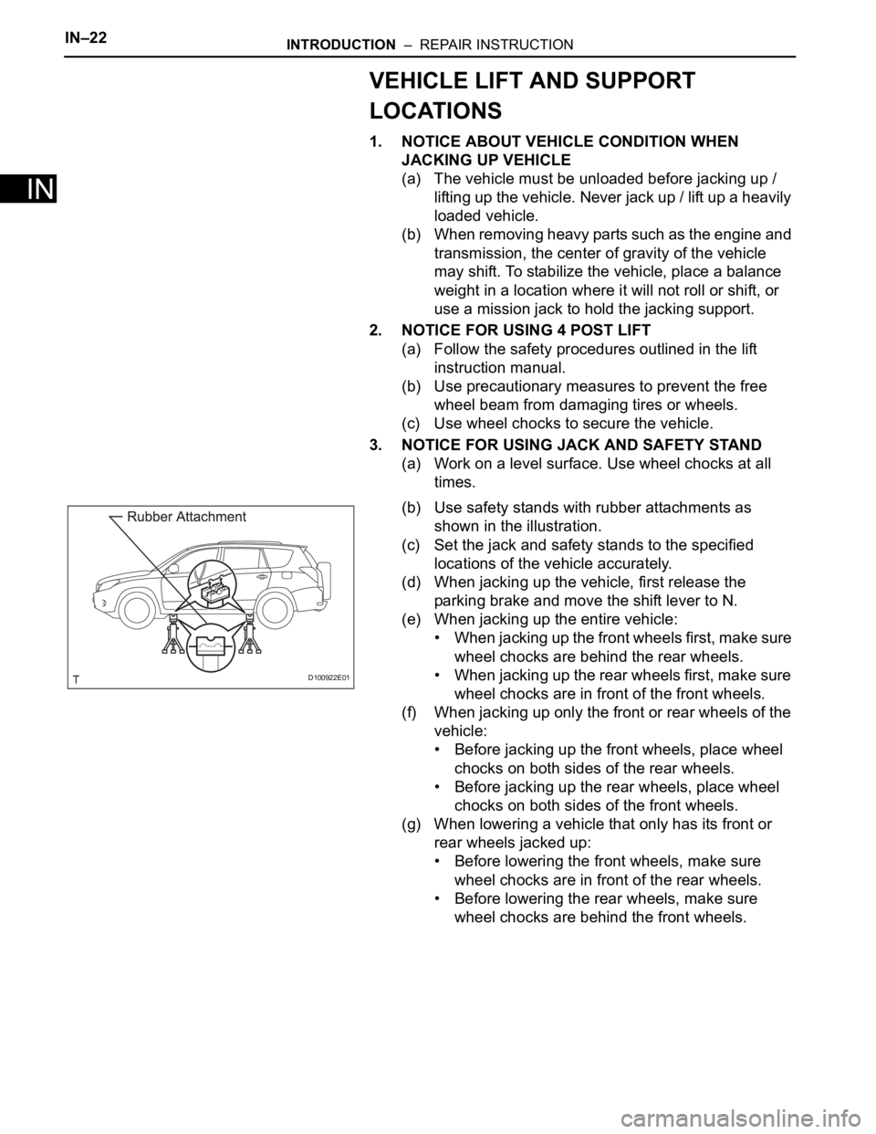
(b) Use safety stands with rubber attachments as
shown in the illustration.
(c) Set the jack and safety stands to the specified
locations of the vehicle accurately.
(d) When jacking up the vehicle, first release the
parking brake and move the shift lever to N.
(e) When jacking up the entire vehicle:
• When jacking up the front wheels first, make sure
wheel chocks are behind the rear wheels.
• When jacking up the rear wheels first, make sure
wheel chocks are in front of the front wheels.
(f) When jacking up only the front or rear wheels of the
vehicle:
• Before jacking up the front wheels, place wheel
chocks on both sides of the rear wheels.
• Before jacking up the rear wheels, place wheel
chocks on both sides of the front wheels.
(g) When lowering a vehicle that only has its front or
rear wheels jacked up:
• Before lowering the front wheels, make sure
wheel chocks are in front of the rear wheels.
• Before lowering the rear wheels, make sure
wheel chocks are behind the front wheels.
D100922E01
Page 419 of 2000

MA–12MAINTENANCE – CHASSIS
MA
GENERAL MAINTENANCE
(2006/01- )
1. INSPECT STEERING LINKAGE AND GEAR HOUSING
(a) Check the steering wheel free play.
(b) Check the steering linkage for looseness or
damage.
(1) Check that the tie rod ends do not have
excessive play.
(2) Check that the dust seals and boots are not
damaged.
(3) Check that the boot clamps are not loose.
(4) Check that the steering gear housing is not
damaged.
(5) Check that the connectors are properly
connected to the steering gear housing.
2. INSPECT BALL JOINTS AND DUST COVERS
(a) Inspect the ball joints for excessive looseness.
(1) Jack up the front of the vehicle and place
wooden blocks with a height of 180 to 200 mm
(7.09 to 7.87 in.) under the front tires.
(2) Lower the vehicle until the front coil spring has
about half its ordinary load. Place stands under
the vehicle for safety.
(3) Check that the front wheels are pointing
straight ahead. Use wheel chocks on all 4
wheels.
(4) Using a lever, pry up the end of the lower arm.
Check the amount of play.
Maximum ball joint vertical play:
0 mm (0 in.)
If there is any play, replace the ball joint.
(b) Check the dust cover for damage.
3. INSPECT DRIVE SHAFT BOOTS
(a) Check the drive shaft boots for loose clamps,
grease leakage, kinks or damage.
4. INSPECT AUTOMATIC TRANSAXLE FLUID LEVEL
(a) Visually check the transmission for fluid leakage. If
oil is leaking, find the cause and repair it.
5. INSPECT TRANSFER OIL (for 4WD)
(a) Visually check the transfer for oil leakage. If oil is
leaking, find the cause and repair it.
6. INSPECT REAR DIFFERENTIAL OIL (for 4WD)
(a) For the rear differential oil inspection, refer to the
following procedures (see page DF-3).
Type See procedures
U151E See page AX-126
U151F See page AX-126
Type See procedures
Front Oil See page TF-45
Rear Oil See page TF-45
Page 420 of 2000

MAINTENANCE – CHASSISMA–13
MA
7. ROTATE TIRES (See page TW-1)
Page 421 of 2000

STEERING COLUMN – STEERING SYSTEMSR–3
SR
PROBLEM SYMPTOMS TABLE
(2006/01- )
HINT:
Use the table below to help determine the cause of the
problem symptom. The potential causes of the symptoms are
listed in order of probability in the "Suspected Area" column
of the table. Check each symptom by checking the suspected
areas in the order they are listed. Replace parts as
necessary.
Steering system
ON-VEHICLE INSPECTION
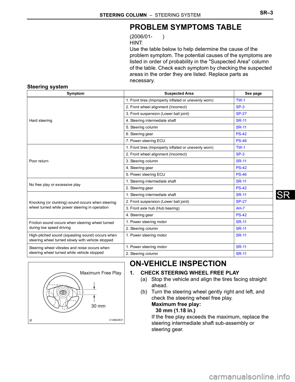
1. CHECK STEERING WHEEL FREE PLAY
(a) Stop the vehicle and align the tires facing straight
ahead.
(b) Turn the steering wheel gently right and left, and
check the steering wheel free play.
Maximum free play:
30 mm (1.18 in.)
If the free play exceeds the maximum, replace the
steering intermediate shaft sub-assembly or
steering gear.
Symptom Suspected Area See page
Hard steering1. Front tires (Improperly inflated or unevenly worn)TW-1
2. Front wheel alignment (Incorrect)SP-3
3. Front suspension (Lower ball joint)SP-27
4. Steering intermediate shaftSR-11
5. Steering columnSR-11
6. Steering gearPS-42
7. Power steering ECUPS-46
Poor return1. Front tires (Improperly inflated or unevenly worn)TW-1
2. Front wheel alignment (Incorrect)SP-3
3. Steering columnSR-11
4. Steering gearPS-42
5. Power steering ECUPS-46
No free play or excessive play1. Steering intermediate shaftSR-11
2. Steering gearPS-42
Knocking (or clunking) sound occurs when steering
wheel turned while power steering in operation1. Steering intermediate shaftSR-11
2. Front suspension (Lower ball joint)SP-27
3. Front axle hub (Hub bearing)AH-7
4. Steering gearPS-42
Friction sound occurs when steering wheel turned
during low speed driving1. Power steering motorSR-11
2. Steering columnSR-11
High-pitched sound (squealing sound) occurs when
steering wheel turned slowly with vehicle stopped1. Power steering motorSR-11
Steering wheel vibrates and noise occurs when
steering wheel turned while vehicle stopped1. Power steering motorSR-11
2. Steering columnSR-11
C128822E01
Page 1343 of 2000

GF1A TRANSFER – ACTIVE TORQUE CONTROL 4WD SYSTEMTF–15
TF
PROBLEM SYMPTOMS TABLE
HINT:
• Use the table below to help determine the cause of the
problem symptom. The potential causes of the symptoms
are listed in order of probability in the "Suspected area"
column of the table. Check each symptom by checking the
suspected areas in the order they are listed. Replace parts
as necessary.
• Inspect the fuses and relays related to this system before
inspecting the suspected areas below.
Active torque control 4WD system
HINT:
*:When driving 4WD mode, the vehicle is hard to turn, as if
the brakes were applied, due to the rotational difference
between the front and rear tires while turning.
Symptom Suspected area See page
Phenomenon of tight-corner braking*1.Steering angle sensor circuitTF-27
2.Linear solenoid circuitTF-30
3.4WD control ECU
4WD indicator light remains ON 4WD indicator light circuitTF-36
4WD indicator light does not come ON 4WD indicator light circuitTF-40
The system is in the DTC output mode although
terminals TC and CG of the DLC3 are not short
circuited1.TC and CG terminal circuitTF-42
2.4WD indicator light circuit
The system is not in the DTC output mode although
terminals TC and CG of the DLC3 are not short
circuited1.TC and CG terminal circuitTF-42
2.4WD indicator light circuit
Page 1479 of 2000

TIRE AND WHEEL – TIRE PRESSURE WARNING SYSTEMTW–7
TW
(b) Under the following conditions, the system may not
function properly;
• Areas, facilities or devices that use similar radio
frequencies are located in the vicinity of the
vehicle.
• Devices using similar radio frequencies are used
in the vehicle.
• Large amounts of snow or ice are stuck to the
vehicle, especially on the wheels and around the
wheel houses.
• The battery of the transmitter is depleted.
• Tires and wheels without tire pressure warning
valves and transmitters are used.
• Snow tires and tire chains are used.
• If wheels other than the specified ones are used,
the system may not function properly because
different radio waves are transmitted from the tire
pressure warning valve and transmitter.
• Depending on the tire type, the tire pressure
warning valve and transmitter may not function
properly even though the specified wheels are
used.
• The system may not function properly if it is
initialized with tire pressures which are not the
specified values.
(c) The average life of the grommet of the tire pressure
warning antenna and receiver is approximately 5
years, at which time it must be replaced. Retighten
the valve nut if the valve is leaking air, if it is less
than 5 years old, and there is no problem with the
grommets.
(d) After removing and installing the ECU or a sensor,
output a diagnosis code and check that it is a
normal code.
3. FUNCTION OF COMPONENTS
Components Function
Tire pressure warning antenna and receiver • Combined as a single unit with a disc wheel air valve, it measures
tire pressure and temperature, and transmits an ID number for
measurement value and identification
• Battery is built into valve
Tire pressure warning antenna and receiver Receives necessary signals from tire pressure warning antenna and
receiver and transmits them to tire pressure warning ECU
Tire pressure warning ECU • Receives signal from receiver and identifies it as vehicle's own
signal.
• If measurement value is equal to or lower than specified value, it
transmits a signal so that the air pressure warning light on
combination meter turns on.
Tire pressure warning light Located in the combination meter, it informs driver of lowered tire air
pressure and system failure
Page 1482 of 2000

TW–10TIRE AND WHEEL – TIRE PRESSURE WARNING SYSTEM
TW
REGISTRATION
1. IN CASE OF TIRE PRESSURE WARNING ECU
REPLACEMENT
(a) Read ID stored in the old ECU using the intelligent
tester.
2. IN CASE OF TIRE PRESSURE WARNING VALVE AND
TRANSMITTER AND/OR TIRE PRESSURE WARNING
ECU REPLACEMENT
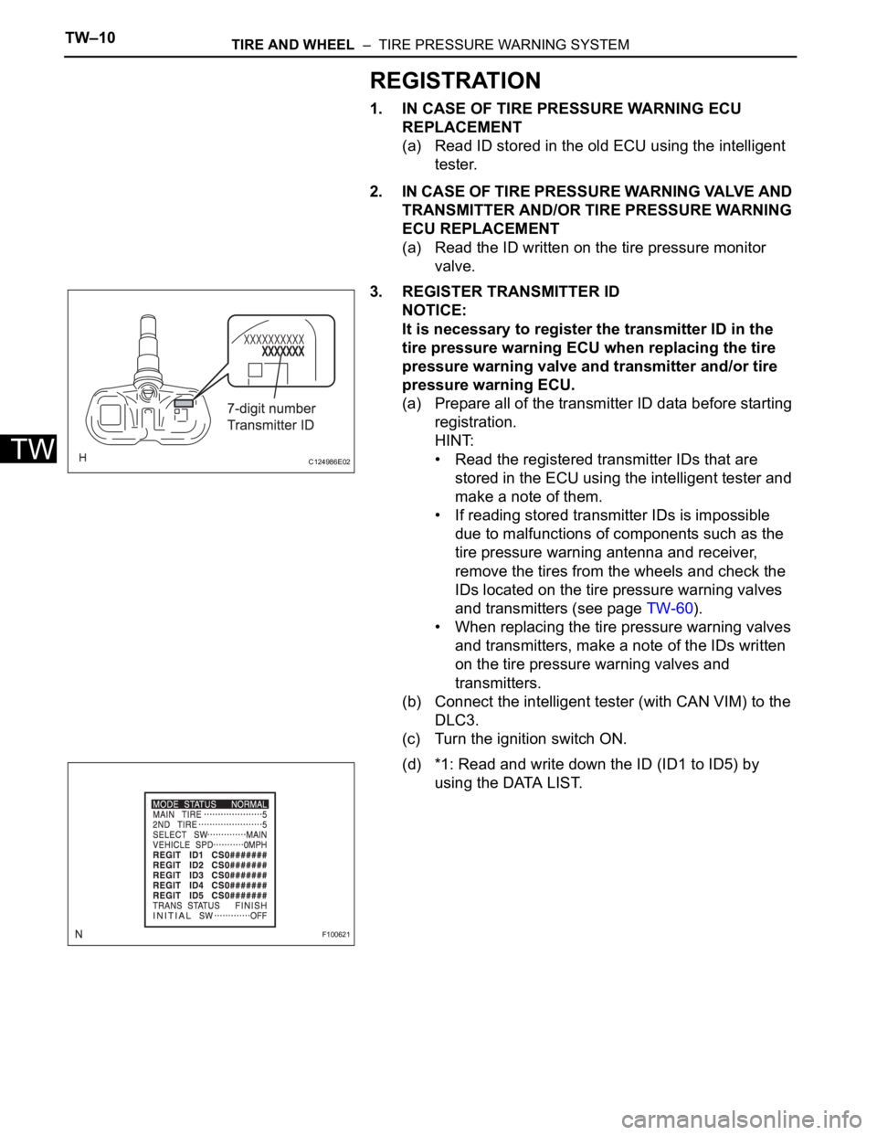
(a) Read the ID written on the tire pressure monitor
valve.
3. REGISTER TRANSMITTER ID
NOTICE:
It is necessary to register the transmitter ID in the
tire pressure warning ECU when replacing the tire
pressure warning valve and transmitter and/or tire
pressure warning ECU.
(a) Prepare all of the transmitter ID data before starting
registration.
HINT:
• Read the registered transmitter IDs that are
stored in the ECU using the intelligent tester and
make a note of them.
• If reading stored transmitter IDs is impossible
due to malfunctions of components such as the
tire pressure warning antenna and receiver,
remove the tires from the wheels and check the
IDs located on the tire pressure warning valves
and transmitters (see page TW-60).
• When replacing the tire pressure warning valves
and transmitters, make a note of the IDs written
on the tire pressure warning valves and
transmitters.
(b) Connect the intelligent tester (with CAN VIM) to the
DLC3.
(c) Turn the ignition switch ON.
(d) *1: Read and write down the ID (ID1 to ID5) by
using the DATA LIST.
C124986E02
F100621
Page 1485 of 2000

TIRE AND WHEEL – TIRE PRESSURE WARNING SYSTEMTW–13
TW
(b) Connect the intelligent tester (with CAN VIM ) to the
DLC3.
(c) Turn the ignition switch ON.
(d) Select "SIGNAL CHECK" mode on the intelligent
tester (with CAN VIM ) (see page TW-12).
(e) Confirm that the transmitter IDs and tire pressure
data for all the tires are displayed on the intelligent
tester screen.
NOTICE:
• It may take up to 1 minute to update the tire
pressure data.
• If the IDs have not been registered, DTC
C2171/71 is set in the tire pressure warning
ECU after approximately 60 minutes.
Page 1500 of 2000

TW–28TIRE AND WHEEL – TIRE PRESSURE WARNING SYSTEM
TW
DESCRIPTION
The tire pressure warning valve and transmitter that is installed in the tires and wheels measures the air
pressure of the tires. The measured values are transmitted to the tire pressure warning receiver on the
body as radio waves and then sent to the tire pressure warning ECU. The ECU compares the measured
air pressure values with the air pressure threshold. When the measured air pressure values are less than
this threshold, the warning light in the combination meter turns on.
The tire pressure warning ECU stores a DTC when the tire pressure monitor valve stops transmitting
signals. At this time, forcibly transmit the signals by releasing the tire pressure rapidly. The stored DTC is
cleared when the signal transmission is resumed.
HINT:
It is necessary to perform the procedure to identify the tire pressure monitor valve that is malfunctioning
because it cannot be identified by the output DTC.
DTC C2111/11 Transmitter ID1 Operation Stop
DTC C2112/12 Transmitter ID2 Operation Stop
DTC C2113/13 Transmitter ID3 Operation Stop
DTC C2114/14 Transmitter ID4 Operation Stop
DTC C2115/15 Transmitter ID5 Operation Stop
DTC No DTC Detection Condition Trouble Area
C 2 111 / 11
C2112/12
C2113/13
C2114/14
C2115/15Tire pressure monitor valve stops transmitting
signals• Tire pressure warning valve and
transmitter
• Tire pressure warning ECU
Page 1502 of 2000

TW–30TIRE AND WHEEL – TIRE PRESSURE WARNING SYSTEM
TW
(e) Rapidly release the pressure from each wheel by
approximately 40 kPa (0.4 kgf/cm
2, 5.8 psi) for 30
seconds or more.
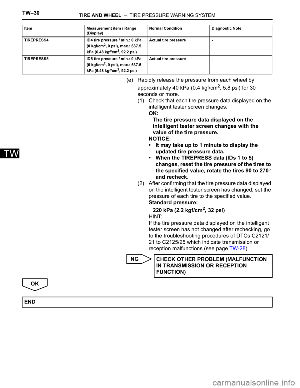
(1) Check that each tire pressure data displayed on the
intelligent tester screen changes.
OK:
The tire pressure data displayed on the
intelligent tester screen changes with the
value of the tire pressure.
NOTICE:
• It may take up to 1 minute to display the
updated tire pressure data.
• When the TIREPRESS data (IDs 1 to 5)
changes, reset the tire pressure of the tires to
the specified value, rotate the tires 90 to 270
and recheck.
(2) After confirming that the tire pressure data displayed
on the intelligent tester screen has changed, set the
pressure of each tire to the specified value.
Standard pressure:
220 kPa (2.2 kgf/cm
2, 32 psi)
HINT:
If the tire pressure data displayed on the intelligent
tester screen has not changed after rechecking, go
to the troubleshooting procedures of DTCs C2121/
21 to C2125/25 which indicate transmission or
reception malfunctions (see page TW-28).
NG
OK
TIREPRESS4 ID4 tire pressure / min.: 0 kPa
(0 kgf/cm2, 0 psi), max.: 637.5
kPa (6.48 kgf/cm2, 92.2 psi) Actual tire pressure -
TIREPRESS5 ID5 tire pressure / min.: 0 kPa
(0 kgf/cm
2, 0 psi), max.: 637.5
kPa (6.48 kgf/cm2, 92.2 psi) Actual tire pressure - Item Measurement item / Range
(Display) Normal Condition Diagnostic Note
CHECK OTHER PROBLEM (MALFUNCTION
IN TRANSMISSION OR RECEPTION
FUNCTION)
END