check engine light TOYOTA RAV4 2022 Owner's Manual
[x] Cancel search | Manufacturer: TOYOTA, Model Year: 2022, Model line: RAV4, Model: TOYOTA RAV4 2022Pages: 748, PDF Size: 22.93 MB
Page 220 of 748
2204-4. Refueling
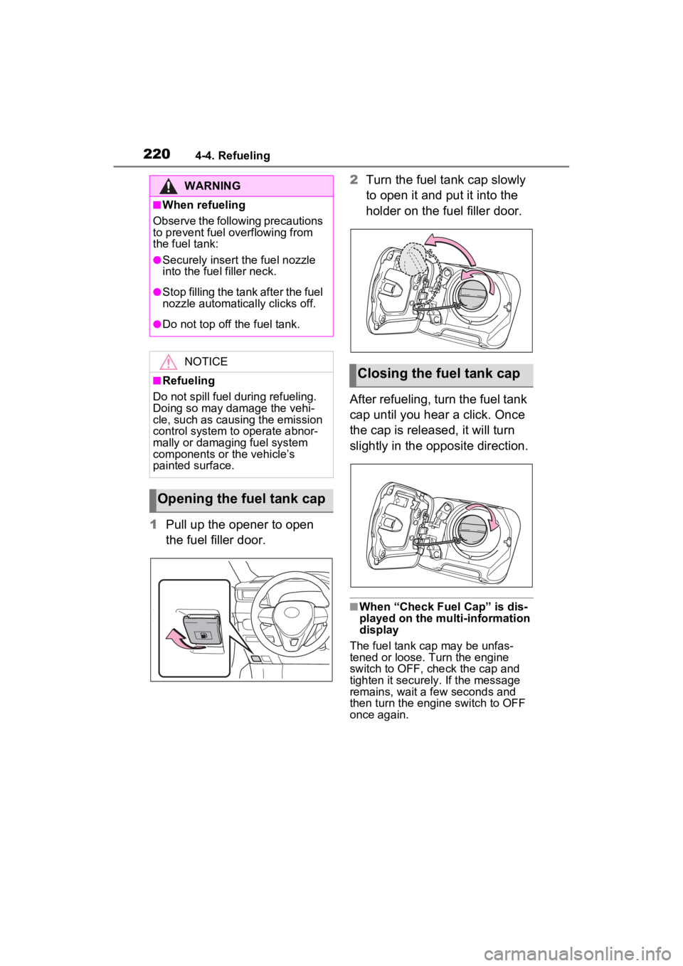
1Pull up the opener to open
the fuel filler door. 2
Turn the fuel tank cap slowly
to open it and put it into the
holder on the fuel filler door.
After refueling, turn the fuel tank
cap until you hear a click. Once
the cap is released, it will turn
slightly in the opposite direction.
■When “Check Fuel Cap” is dis-
played on the multi-information
display
The fuel tank cap may be unfas-
tened or loose. Turn the engine
switch to OFF, check the cap and
tighten it securely. If the message
remains, wait a few seconds and
then turn the engine switch to OFF
once again.
WARNING
■When refueling
Observe the following precautions
to prevent fuel overflowing from
the fuel tank:
●Securely insert the fuel nozzle
into the fuel filler neck.
●Stop filling the tank after the fuel
nozzle automatically clicks off.
●Do not top off the fuel tank.
NOTICE
■Refueling
Do not spill fuel during refueling.
Doing so may damage the vehi-
cle, such as causing the emission
control system to operate abnor-
mally or damaging fuel system
components or the vehicle’s
painted surface.
Opening the fuel tank cap
Closing the fuel tank cap
Page 353 of 748
3534-5. Using the driving support systems
4
Driving
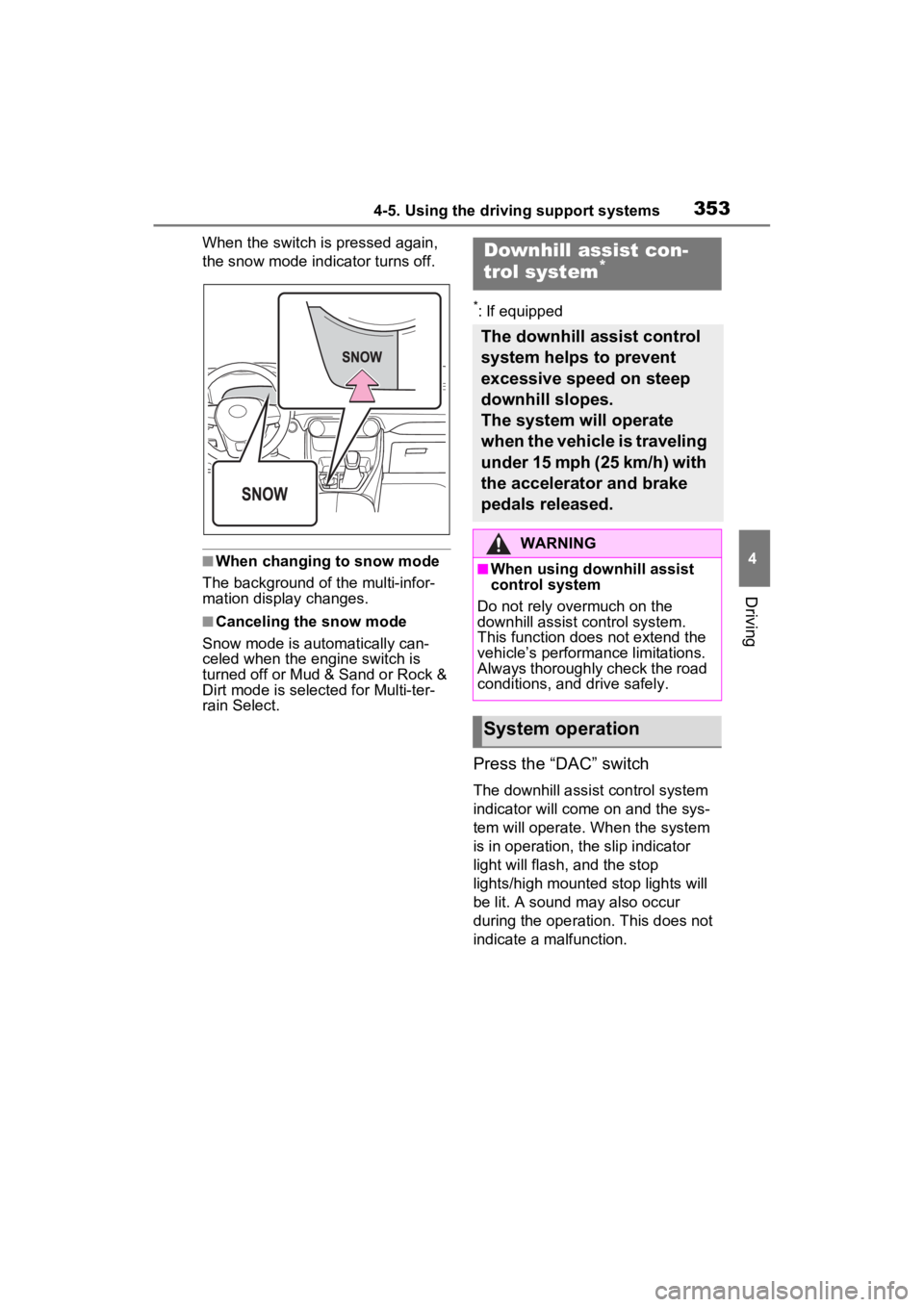
When the switch is pressed again,
the snow mode indicator turns off.
■When changing to snow mode
The background of the multi-infor-
mation display changes.
■Canceling the snow mode
Snow mode is automatically can-
celed when the engine switch is
turned off or Mud & Sand or Rock &
Dirt mode is selec ted for Multi-ter-
rain Select.
*: If equipped
Press the “DAC” switch
The downhill assist control system
indicator will come on and the sys-
tem will operate. When the system
is in operation, the slip indicator
light will flash, and the stop
lights/high mounted stop lights will
be lit. A sound may also occur
during the operati on. This does not
indicate a malfunction.
Downhill assist con-
trol system*
The downhill assist control
system helps to prevent
excessive speed on steep
downhill slopes.
The system will operate
when the vehicle is traveling
under 15 mph (25 km/h) with
the accelerator and brake
pedals released.
WARNING
■When using downhill assist
control system
Do not rely overmuch on the
downhill assist control system.
This function does not extend the
vehicle’s performance limitations.
Always thoroughly check the road
conditions, and drive safely.
System operation
Page 354 of 748
3544-5. Using the driving support systems
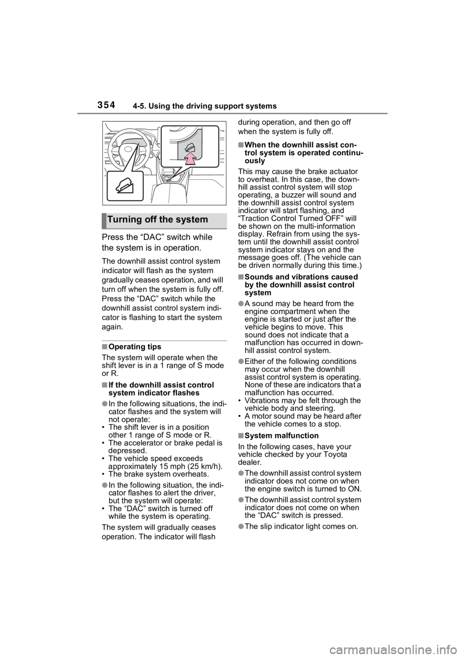
Press the “DAC” switch while
the system is in operation.
The downhill assist control system
indicator will flash as the system
gradually ceases operation, and will
turn off when the system is fully off.
Press the “DAC” switch while the
downhill assist control system indi-
cator is flashing to start the system
again.
■Operating tips
The system will op erate when the
shift lever is in a 1 range of S mode
or R.
■If the downhill assist control
system indicator flashes
●In the following situations, the indi-
cator flashes and the system will
not operate:
• The shift lever is in a position other 1 range of S mode or R.
• The accelerator or brake pedal is depressed.
• The vehicle speed exceeds
approximately 15 mph (25 km/h).
• The brake system overheats.
●In the following si tuation, the indi-
cator flashes to a lert the driver,
but the system will operate:
• The “DAC” switch is turned off
while the system is operating.
The system will gr adually ceases
operation. The indicator will flash during operation,
and then go off
when the system is fully off.
■When the downhill assist con-
trol system is operated continu-
ously
This may cause the brake actuator
to overheat. In thi s case, the down-
hill assist control system will stop
operating, a buzze r will sound and
the downhill assist control system
indicator will start flashing, and
“Traction Contro l Turned OFF” will
be shown on the mu lti-information
display. Refrain from using the sys-
tem until the downhill assist control
system indicator stays on and the
message goes off. (The vehicle can
be driven normally during this time.)
■Sounds and vibrations caused
by the downhill assist control
system
●A sound may be heard from the
engine compartment when the
engine is started or just after the
vehicle begins to move. This
sound does not indicate that a
malfunction has occurred in down-
hill assist control system.
●Either of the following conditions
may occur when the downhill
assist control system is operating.
None of these are indicators that a
malfunction has occurred.
• Vibrations may be felt through the
vehicle body and steering.
• A motor sound may be heard after the vehicle comes to a stop.
■System malfunction
In the following ca ses, have your
vehicle checked by your Toyota
dealer.
●The downhill assist control system
indicator does not come on when
the engine switch is turned to ON.
●The downhill assist control system
indicator does not come on when
the “DAC” switch is pressed.
●The slip indicator light comes on.
Turning off the system
Page 542 of 748
5426-4. Using the other interior features
Repeatedly flashes 4 times
continuously (Orange)
■The wireless charger can be
operated when
The engine switch is in ACC or ON.
■Usable portable devices
●Qi standard wireless charge stan-
dard can be used on compatible
devices. However, not all Qi stan-
dard devices and compatibility are
guaranteed.
●Starting with mobile phones and
smartphones, it is aimed for low
power electrically supplied porta-
ble devices of no more than 5W.
●However, charging exceeding 5 W
is supported by the following por-
table devices.
• Charging at 7.5 W or less is sup-
ported by iPhone’s that support
7.5 W charging.
• Charging at 10 W or less is sup-
ported by portable devices compli-
ant with WPC standard Ver1.2.4.
■Using the smart key system
If the smart key system detects the
key while a device is being charged,
charging will be temporarily
stopped.
■When covers and accessories
are attached to portable devices
Do not charge in situations where
cover and accessories not able to
handle Qi are attached to the porta-
ble device. Depending on the type
of cover and acce ssory, it may not
be possible to charge. When
charging is not performed even with
the portable devic e placed on the
charge area, remove the cover and
accessories.
■While charging, noise enters
the AM radio
●Turn off the wireless charger and
confirm that the noise has
decreased. If the noise
decreases, continuously pushing
the power supply switch of the
wireless charger for 2 seconds,
the frequency of the charger can
be changed and the noise can be
reduced. Also, on that occasion,
the operation indicator light will
flash orange 2 times.
●iPhone’s use a particular fre-
quency for rapid charging.
Depending on the iOS version,
rapid charging may not be per-
formed while switching frequen-
cies.
Portable device
misaligned:
The charging coil
in the portable
device moved
outside of the
charge area, and
so the abnormal
heating preven-
tion function of
the charging coil
operated
Remove the por-
table device from
the charging
tray, check that
the operation
indicator light
switches back to
green, and then
once again place
the device near
the center of the
charging tray. If
there is a case or
cover attached
to the portable
device, remove
it.
Suspected
causesHandling method
Safety shut-
down resulting
when the tem-
perature within
the wireless
charger
exceeded the set
valueStop charging,
remove the por-
table device from
the charging
tray, wait for the
temperature to
drop, and then
start charging
again.
Suspected causesHandling method
Page 555 of 748
555
7
7
Maintenance and care
Maintenance and care
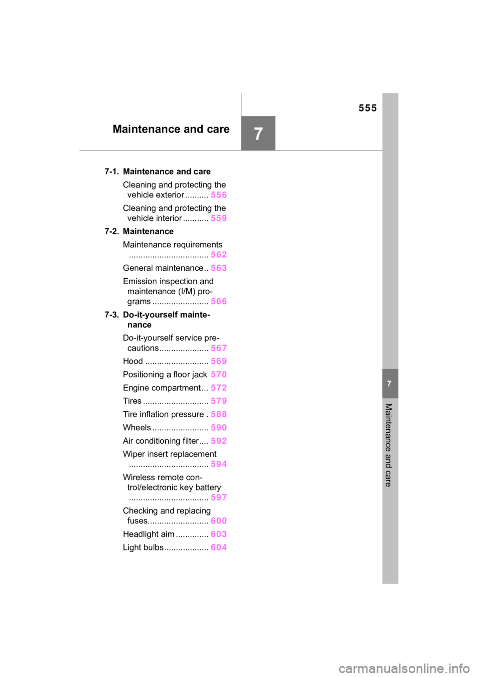
7-1. Maintenance and careCleaning and protecting the vehicle exterior .......... 556
Cleaning and protecting the vehicle interior ........... 559
7-2. Maintenance Maintenance requirements.................................. 562
General maintenance.. 563
Emission inspection and maintenance (I/M) pro-
grams ........................ 566
7-3. Do-it-yourself mainte- nance
Do-it-yourself service pre- cautions ..................... 567
Hood ........................... 569
Positioning a floor jack 570
Engine compartment ... 572
Tires ............................ 579
Tire inflation pressure . 588
Wheels ......... ...............590
Air conditioning filter .... 592
Wiper insert replacement .................................. 594
Wireless remote con- trol/electronic key battery.................................. 597
Checking and replacing fuses.......................... 600
Headlight aim .............. 603
Light bulbs................... 604
Page 563 of 748
5637-2. Maintenance
7
Maintenance and care
■Resetting the message indicat-
ing maintenance is required
After the required maintenance is
performed according to the mainte-
nance schedule, please reset the
reminder light or message.
To reset the reminder light or mes-
sage, follow the procedure
described below:
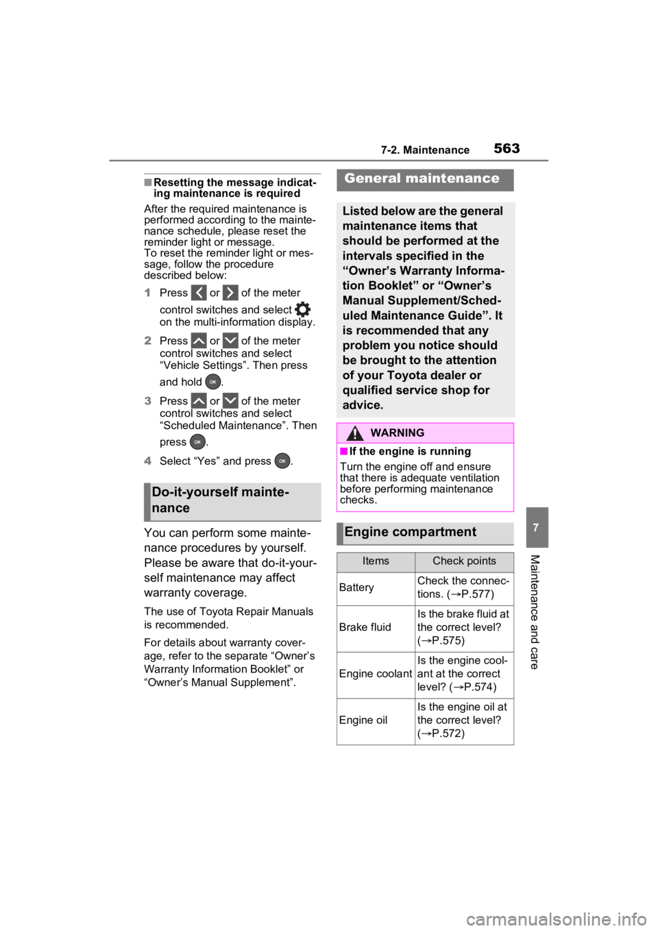
1 Press or of the meter
control switches and select
on the multi-information display.
2 Press or of the meter
control switches and select
“Vehicle Settings”. Then press
and hold .
3 Press or of the meter
control switches and select
“Scheduled Maintenance”. Then
press .
4 Select “Yes” and press .
You can perform some mainte-
nance procedures by yourself.
Please be aware that do-it-your-
self maintenance may affect
warranty coverage.
The use of Toyota Repair Manuals
is recommended.
For details about warranty cover-
age, refer to the separate “Owner’s
Warranty Information Booklet” or
“Owner’s Manual Supplement”.
Do-it-yourself mainte-
nance
General maintenance
Listed below are the general
maintenance items that
should be performed at the
intervals specified in the
“Owner’s Warranty Informa-
tion Booklet” or “Owner’s
Manual Supplement/Sched-
uled Maintenance Guide”. It
is recommended that any
problem you notice should
be brought to the attention
of your Toyota dealer or
qualified service shop for
advice.
WARNING
■If the engine is running
Turn the engine o ff and ensure
that there is adequate ventilation
before performing maintenance
checks.
Engine compartment
ItemsCheck points
BatteryCheck the connec-
tions. ( P.577)
Brake fluid
Is the brake fluid at
the correct level?
( P.575)
Engine coolant
Is the engine cool-
ant at the correct
level? ( P.574)
Engine oil
Is the engine oil at
the correct level?
( P.572)
Page 577 of 748
5777-3. Do-it-yourself maintenance
7
Maintenance and care
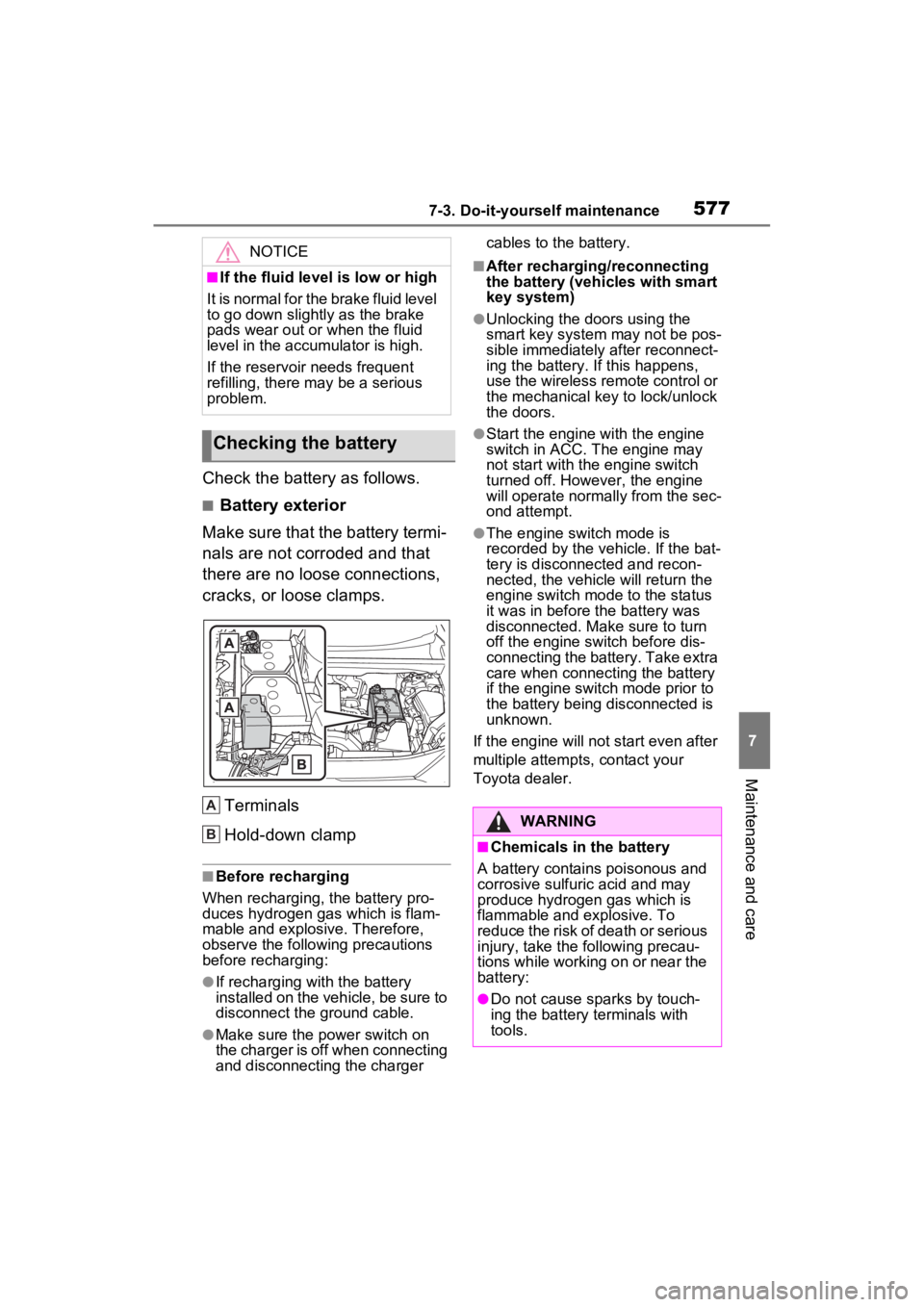
Check the battery as follows.
■Battery exterior
Make sure that the battery termi-
nals are not corroded and that
there are no loose connections,
cracks, or loose clamps.
Terminals
Hold-down clamp
■Before recharging
When recharging, t he battery pro-
duces hydrogen ga s which is flam-
mable and explosive. Therefore,
observe the following precautions
before recharging:
●If recharging wi th the battery
installed on the vehicle, be sure to
disconnect the ground cable.
●Make sure the power switch on
the charger is off when connecting
and disconnecting the charger cables to the battery.
■After recharging/reconnecting
the battery (vehicles with smart
key system)
●Unlocking the doors using the
smart key system may not be pos-
sible immediately
after reconnect-
ing the battery. If this happens,
use the wireless remote control or
the mechanical key to lock/unlock
the doors.
●Start the engine with the engine
switch in ACC. T he engine may
not start with th e engine switch
turned off. However, the engine
will operate normally from the sec-
ond attempt.
●The engine switch mode is
recorded by the vehicle. If the bat-
tery is disconnected and recon-
nected, the vehicle will return the
engine switch mode to the status
it was in before t he battery was
disconnected. Make sure to turn
off the engine switch before dis-
connecting the battery. Take extra
care when connecting the battery
if the engine switch mode prior to
the battery being disconnected is
unknown.
If the engine will no t start even after
multiple attempts, contact your
Toyota dealer.
NOTICE
■If the fluid level is low or high
It is normal for the brake fluid level
to go down slightly as the brake
pads wear out or when the fluid
level in the accumulator is high.
If the reservoir needs frequent
refilling, there may be a serious
problem.
Checking the battery
A
B�:�$�5�1�,�1�*
■Chemicals in the battery
A battery contains poisonous and
corrosive sulfur ic acid and may
produce hydrogen gas which is
flammable and explosive. To
reduce the risk of death or serious
injury, take the following precau-
tions while working on or near the
battery:
●Do not cause sparks by touch-
ing the battery terminals with
tools.
Page 582 of 748
5827-3. Do-it-yourself maintenance
■When rotating the tires (vehi-
cles with tire pressure warning
system)
Make sure that the engine switch is
OFF. If the tires are rotated while
the engine switch i s in ON, the tire
position informa tion will not be
updated. If this accidentally occurs,
either turn the engine switch to OFF
and then to ON, or initialize the sys-
tem after checking that the tire pres-
sure is properly adjusted.
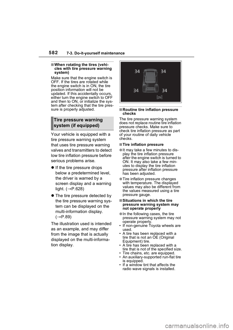
Your vehicle is equipped with a
tire pressure warning system
that uses tire pressure warning
valves and transmitters to detect
low tire inflation pressure before
serious problems arise.
If the tire pressure drops
below a predetermined level,
the driver is warned by a
screen display and a warning
light. ( P.628)
The tire pressure detected by
the tire pressure warning sys-
tem can be displayed on the
multi-information display.
( P.89)
The illustration used is intended
as an example, and may differ
from the image that is actually
displayed on the multi-informa-
tion display.
■Routine tire inflation pressure
checks
The tire pressure warning system
does not replace routine tire inflation
pressure checks . Make sure to
check tire inflation pressure as part
of your routine o f daily vehicle
checks.
■Tire inflation pressure
●It may take a few minutes to dis-
play the tire inflation pressure
after the engine switch is turned to
ON. It may also take a few min-
utes to display the tire inflation
pressure after infl ation pressure
has been adjusted.
●Tire inflation pressure changes
with temperature. The displayed
values may also be different from
the values measured using a tire
pressure gauge.
■Situations in which the tire
pressure warning system may
not operate properly
●In the following cases, the tire
pressure warning system may not
operate properly.
• If non-genuine Toyota wheels are used.
• A tire has been replaced with a tire that is not an OE (Original
Equipment) tire.
• A tire has been replaced with a tire that is not of the specified size.
• Tire chains, etc. are equipped.
• An auxiliary-support ed run-flat tire
is equipped.
• If a window tint that affects the radio wave signals is installed.
Tire pressure warning
system (if equipped)
Page 630 of 748

6308-2. Steps to take in an emergency
the warning light to flash and the
warning buzzer to sound even if a
passenger is not sitting in the
seat.
●If a cushion is placed on the seat,
the sensor may not detect a pas-
senger, and the warning light may
not operate properly.
■SRS warning light
This warning light system monitors
the airbag sensor assembly, front
impact sensors, side impact sensors
(front door), side impact sensors
(front), driver’s seat position sen-
sor, driver’s seat belt buckle switch,
front passenger occupant classifica-
tion system (ECU and sensors),
“AIR BAG ON” indicator light, “AIR
BAG OFF” indicator light, front pas-
senger’s seat belt buckle switch,
driver’s seat belt p retensioner, front
passenger’s seat be lt pretensioner
and force limiter, airbags, intercon-
necting wiring and power sources.
( P.36)
■If the malfunction indicator
lamp comes on while driving
First check the following:
●Is the fuel t ank empty?
If it is, fill the fuel tank immediately.
●Is the fuel tank cap loose?
If it is, tighten it securely.
The light will go o ff after several
driving trips.
If the light does not go off even after
several trips, contact your Toyota
dealer as soon as possible.
■Electric power steering system
warning light (warning buzzer)
When the battery charge becomes
insufficient or the voltage temporar-
ily drops, the electric power steering
system warning light may come on
and the warning buzzer may sound.
■When the tire pressure warning
light comes on ( vehicles with
tire pressure warning system)
Inspect the tires to check if a tire is
punctured.
If a tire is punctured: P.637
If none of the tires are punctured:
Turn the engine switch to OFF then
turn it to ON. Check if the tire pres-
sure warning light comes on or
blinks.
If the tire pressur e warning light
blinks for approximately 1 minute
then stays on
There may be a malfunction in the
tire pressure warning system. Have
the vehicle inspected by your
Toyota dealer immediately.
If the tire pressur e warning light
comes on
1 After the temperature of the tires
has lowered sufficiently, check
the inflation pressure of each tire
and adjust them to the specified
level.
2 If the warning light does not turn
off even after several minutes
have elapsed, check that the
inflation pressure of each tire is
at the specified level and perform
initialization. ( P.584)
■The tire pressure warning light
may come on due to natural
causes (vehicles with tire pres-
sure warning system)
The tire pressure warning light may
come on due to natural causes such
as natural air leaks and tire inflation
pressure changes caused by tem-
perature. In this ca se, adjusting the
tire inflation pressure will turn off the
warning ligh t (after a few minutes).
■When a tire is replaced with a
compact spare tire (vehicles
with tire pressure warning sys-
tem)
The compact spare tire is not
equipped with a tire pressure warn-
Page 647 of 748
6478-2. Steps to take in an emergency
8
When trouble arises
The battery terminal connec-
tions may be loose or cor-
roded.
The engine starting system may
be malfunctioning due to an
electrical problem such as elec-
tronic key battery depletion or a
blown fuse. However, an interim
measure is available to start the
engine. ( P.647)
One of the following may be the
cause of the problem:
The battery may be dis-
charged. ( P.650)
One or both of the battery ter-
minals may be disconnected.
Contact your Toyota dealer if
the problem cannot be repaired,
or if repair procedures are
unknown.
When the engine does not start,
the following steps can be used as an interim measure to start
the engine if the engine switch is
functioning normally:
1
Pull the parking brake switch
to check that the parking
brake is set. ( P.201)
Parking brake indicator will come
on.
2 Shift the shift lever to P.
3 Turn the engine switch to
ACC.
4 Press and hold the engine
switch for about 15 seconds
while depressing the brake
pedal firmly.
Even if the engine can be
started using the above steps,
the system may be malfunction-
ing. Have the vehicle inspected
by your Toyota dealer.
The starter motor does
not turn over (vehicles
with smart key system)
The starter motor does
not turn over, the interior
lights and headlights do
not turn on, or the horn
does not sound
Emergency start function
(vehicles with smart key
system)