TOYOTA RAV4 PRIME 2021 Owners Manual (in English)
Manufacturer: TOYOTA, Model Year: 2021, Model line: RAV4 PRIME, Model: TOYOTA RAV4 PRIME 2021Pages: 616, PDF Size: 34.66 MB
Page 531 of 616

5318-2. Steps to take in an emergency
8
When trouble arises
5Raise the vehicle until the tire
is slightly raised off the
ground.
6 Remove all the wheel nuts
and the tire.
When resting the tire on the
ground, place the tire so that the
wheel design faces up to avoid
scratching the wheel surface.
1 Remove any dirt or foreign
matter from the wheel con-
tact surface.
If foreign matter is on the wheel
contact surface, the wheel nuts
may loosen while the vehicle is in
WARNING
■Replacing a flat tire
●Do not touch the disc wheels or
the area around the brakes
immediately after the vehicle
has been driven.
After the vehicle has been
driven the disc wheels and the
area around the brakes will be
extremely hot. Touching these
areas with hands , feet or other
body parts while changing a tire,
etc. may result in burns.
●Failure to follow these precau-
tions could cause the wheel
nuts to loosen and the tire to fall
off, resulting in death or serious
injury.
• Have the wheel nuts tightened
with a torque wrench to 76 ft•lbf
(103 N•m, 10.5 kgf•m) as soon
as possible after changing
wheels.
• When installing a tire, only use wheel nuts that have been spe-
cifically designed for that wheel.
• If there are any cracks or defor- mations in the bolt screws, nut
threads or bolt holes of the
wheel, have the vehicle
inspected by your Toyota
dealer.
●For vehicles with power back
door: In cases such as when
replacing tires, make sure to
turn off the po wer back door
system ( P.216). Failure to do
so may cause the back door to
operate unintentionally if the
power back door switch is acci-
dentally touched , resulting in
hands and fingers being caught
and injured.
Installing the spare tire
Page 532 of 616
5328-2. Steps to take in an emergency
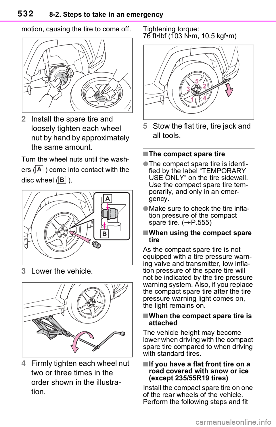
motion, causing the tire to come off.
2Install the spare tire and
loosely tighten each wheel
nut by hand by approximately
the same amount.
Turn the wheel nuts until the wash-
ers ( ) come into contact with the
disc wheel ( ).
3Lower the vehicle.
4 Firmly tighten each wheel nut
two or three times in the
order shown in the illustra-
tion.
Tightening torque:
76 ft•lbf (103 N•m, 10.5 kgf•m)
5Stow the flat tire, tire jack and
all tools.
■The compact spare tire
●The compact spare tire is identi-
fied by the label “TEMPORARY
USE ONLY” on the tire sidewall.
Use the compact spare tire tem-
porarily, and only in an emer-
gency.
●Make sure to check the tire infla-
tion pressure of the compact
spare tire. ( P.555)
■When using the compact spare
tire
As the compact spare tire is not
equipped with a tire pressure warn-
ing valve and transm itter, low infla-
tion pressure of t he spare tire will
not be indicated by the tire pressure
warning system. Also , if you replace
the compact spare ti re after the tire
pressure warning light comes on,
the light remains on.
■When the compact spare tire is
attached
The vehicle height may become
lower when driving with the compact
spare tire compared to when driving
with standard tires.
■If you have a flat front tire on a
road covered wit h snow or ice
(except 235/55R19 tires)
Install the compact spare tire on one
of the rear wheels of the vehicle.
Perform the following steps and fit
A
B
Page 533 of 616

5338-2. Steps to take in an emergency
8
When trouble arises
tire chains to the front tires:
1Replace a rear tire with the com-
pact spare tire.
2 Replace the flat front tire with the
tire removed from the rear of the
vehicle.
3 Fit tire chains to the front tires.
WARNING
■When using the compact
spare tire
●Remember that the compact
spare tire provided is specifi-
cally designed for use with your
vehicle. Do not use your com-
pact spare tire on another vehi-
cle.
●Do not use more than one com-
pact spare tire simultaneously.
●Replace the compact spare tire
with a standard tire as soon as
possible.
●Avoid sudden acceleration,
abrupt steering, sudden brak-
ing and shifting operations that
cause sudden engine braking.
■When the compact spare tire
is attached
The vehicle speed may not be
correctly detecte d, and the follow-
ing systems may not operate cor-
rectly:
• ABS & Brake assist
• VSC/Trailer Sway Control
• TRAC
• Dynamic radar cruise control with full-speed range
• PCS (Pre-Collision System)
• EPS
• LTA (Lane Tracing Assist)
• Tire pressure warning system
• AHB (Automatic High Beam)
• AFS (Adaptive Front-lighting System) (if equipped)
• BSM (Blind Spot Monitor)
• Rear view monitor system (if equipped)
• Panoramic view monitor (if equipped)
• Toyota parking assist monitor (if equipped)
• Intuitive parking assist (if equipped)
• PKSB (Parking Support Brake) (if equipped)
• Navigation system (if equipped)
Also, not only c an the following
system not be utilized fully, but it
may actually negatively affect the
drive-train components:
• E-Four (Electronic On-Demand AWD system)
■Speed limit when using the
compact spare tire
Do not drive at speeds in excess
of 50 mph (80 km /h) when a com-
pact spare tire is installed on the
vehicle.
The compact spare tire is not
designed for driving at high
speeds. Failure to observe this
precaution may lead to an acci-
dent causing death or serious
injury.
■After using the tools and jack
Before driving, ma ke sure all the
tools and jack are securely in
place in their storage location to
reduce the possibility of personal
injury during a collision or sudden
braking.
Page 534 of 616
5348-2. Steps to take in an emergency
One of the following may be the
cause of the problem:
The AC charging cable may
be attached to the vehicle.
( P.123)
The electronic key may not be
functioning properly.
( P.537)
There may not be sufficient
fuel in the vehicle’s tank.
Refuel the vehicle. ( P.306)
There may be a malfunction
in the immobilizer system.
( P.72)
There may be a malfunction
in the steering lock system.
The hybrid system may be
malfunctioning due to an elec-
trical problem such as elec-
tronic key battery depletion or
a blown fuse. However,
depending on the type of mal-
NOTICE
■Be careful when driving over
bumps with the compact
spare tire installed on the
vehicle
The vehicle height may become
lower when driving with the com-
pact spare tire compared to when
driving with standard tires. Be
careful when driving over uneven
road surfaces.
■Driving with tire chains and
the compact spare tire
Do not fit tire chains to the com-
pact spare tire.
Tire chains may damage the vehi-
cle body and adversely affect driv-
ing performance.
■When replacing the tires
When removing or fitting the
wheels, tires or the tire pressure
warning valve and transmitter,
contact your Toyota dealer as the
tire pressure warning valve and
transmitter may be damaged if not
handled correctly.
If the hybrid system
will not start
Reasons for the hybrid sys-
tem not starting vary
depending on the situation.
Check the following and
perform the appropriate
procedure:
The hybrid system will not
start even though the cor-
rect starting procedure is
being followed ( P.279)
Page 535 of 616
5358-2. Steps to take in an emergency
8
When trouble arises
function, an interim measure
is available to start the hybrid
system. (P.535)
There is a possibility that the
temperature of the hybrid bat-
tery (traction battery) is
extremely low (approximately
below -22°F [-30°C]).
( P.280)
One of the following may be the
cause of the problem:
The 12-volt battery may be
discharged. ( P.539)
The 12-volt battery terminal
connections may be loose or
corroded. ( P.467)
One of the following may be the
cause of the problem:
The 12-volt battery may be
discharged. ( P.539)
One or both of the 12-volt bat-
tery terminals may be discon-
nected. ( P.467)
Contact your Toyota dealer if
the problem cannot be repaired,
or if repair procedures are unknown.
When the hybrid system does
not start, the following steps can
be used as an interim measure
to start the hybrid system if the
power switch is functioning nor-
mally.
Do not use this starting proce-
dure except in cases of emer-
gency.
1
Pull the parking brake switch
to check that the parking
brake is set. ( P.290)
Parking brake indicator will come
on.
2 Shift the shift lever to P.
3 Turn the power switch to
ACC.
4 Press and hold the power
switch for about 15 seconds
while depressing the brake
pedal firmly.
Even if the hybrid system can be
started using the above steps,
the system may be malfunction-
ing. Have the vehicle inspected
by your Toyota dealer.
The interior lights and
headlights are dim, or the
horn does not sound or
sounds at a low volume
The interior lights and
headlights do not turn on,
or the horn does not
sound
Starting the hybrid sys-
tem in an emergency
Page 536 of 616
5368-2. Steps to take in an emergency
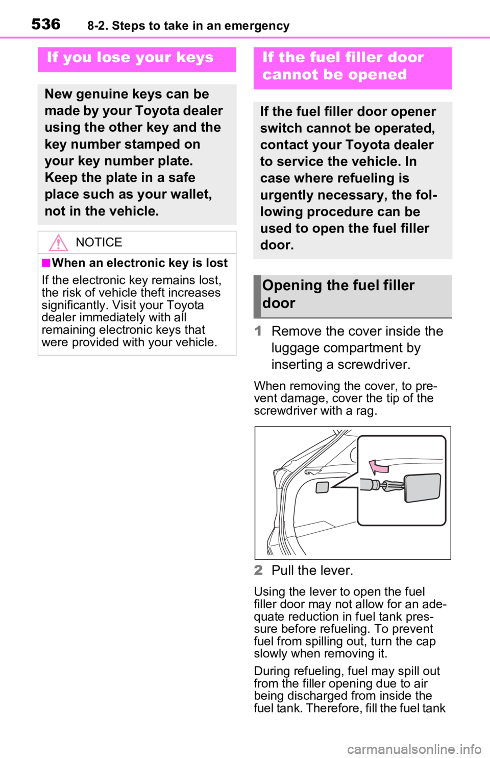
1Remove the cover inside the
luggage compartment by
inserting a screwdriver.
When removing the cover, to pre-
vent damage, cover the tip of the
screwdriver with a rag.
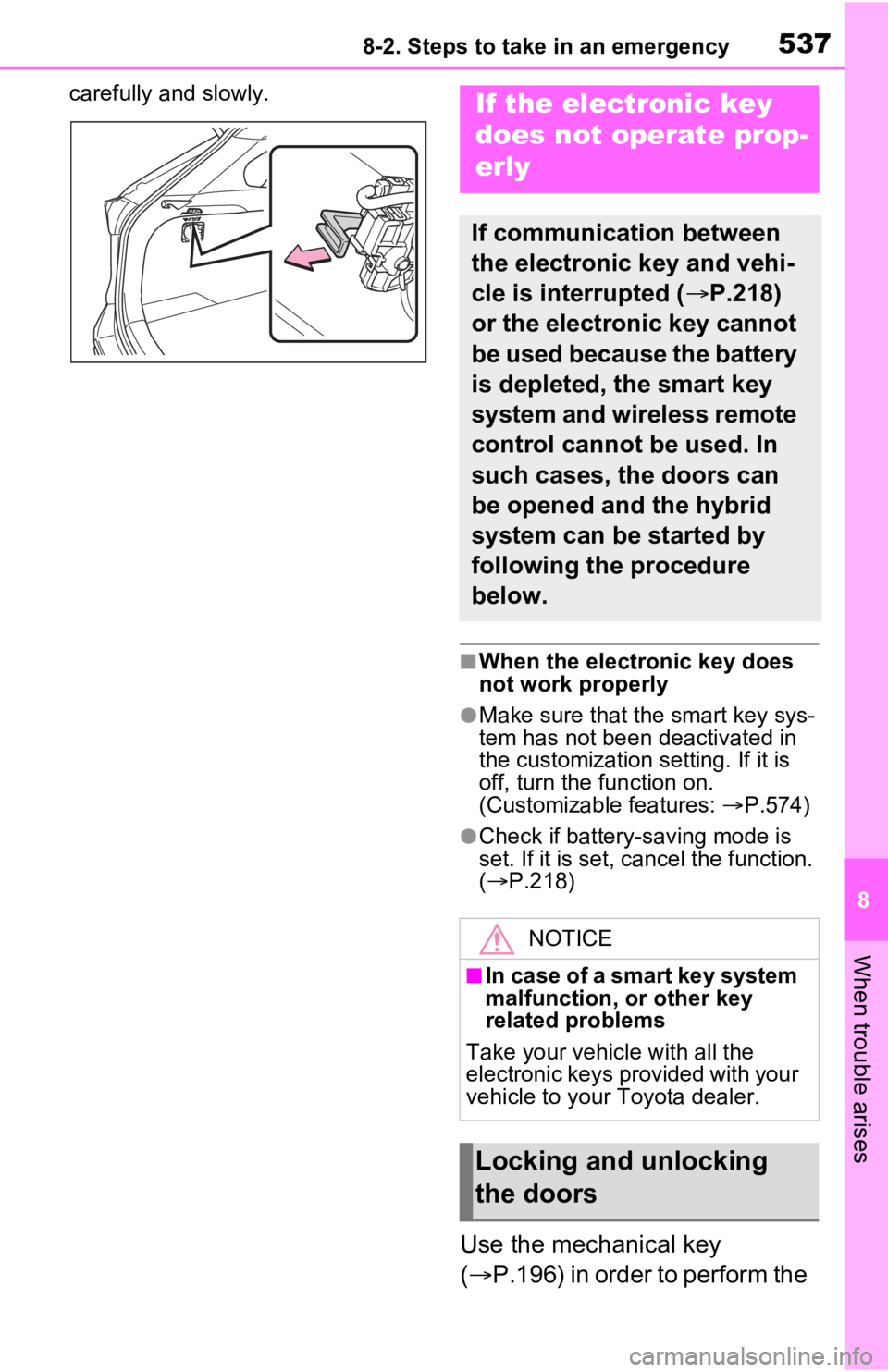
2Pull the lever.
Using the lever to open the fuel
filler door may no t allow for an ade-
quate reduction in fuel tank pres-
sure before refueling. To prevent
fuel from spilling out, turn the cap
slowly when removing it.
During refueling, fuel may spill out
from the filler opening due to air
being discharged from inside the
fuel tank. Therefore, fill the fuel tank
If you lose your keys
New genuine keys can be
made by your Toyota dealer
using the other key and the
key number stamped on
your key number plate.
Keep the plate in a safe
place such as your wallet,
not in the vehicle.
NOTICE
■When an electronic key is lost
If the electronic key remains lost,
the risk of vehicle theft increases
significantly. Visit your Toyota
dealer immediately with all
remaining electronic keys that
were provided wit h your vehicle.
If the fuel filler door
cannot be opened
If the fuel filler door opener
switch cannot be operated,
contact your Toyota dealer
to service the vehicle. In
case where refueling is
urgently necessary, the fol-
lowing procedure can be
used to open the fuel filler
door.
Opening the fuel filler
door
Page 537 of 616
5378-2. Steps to take in an emergency
8
When trouble arises
carefully and slowly.
■When the electronic key does
not work properly
●Make sure that the smart key sys-
tem has not been deactivated in
the customization setting. If it is
off, turn the function on.
(Customizable features: P.574)
●Check if battery-saving mode is
set. If it is set, cancel the function.
( P.218)
Use the mechanical key
( P.196) in order to perform the
If the electronic key
does not operate prop-
erly
If communication between
the electronic key and vehi-
cle is interrupted ( P.218)
or the electronic key cannot
be used because the battery
is depleted, the smart key
system and wireless remote
control cannot be used. In
such cases, the doors can
be opened and the hybrid
system can be started by
following the procedure
below.
NOTICE
■In case of a smart key system
malfunction, o r other key
related problems
Take your vehicle with all the
electronic keys provided with your
vehicle to your Toyota dealer.
Locking and unlocking
the doors
Page 538 of 616

5388-2. Steps to take in an emergency
following operations.
1Locks all the doors
2 Unlocks the door
Turning the key rearward unlocks
the driver’s door. Turning the key
once again within 5 seconds
unlocks the other doors.
■Key linked functions
1 Closes the windows and the
moon roof
*1 or panoramic moon
roof
*1 (turn and hold)*2
2 Opens the windows and the
moon roof
*1 or panoramic moon
roof
*1 (turn and hold)*2
*1
: If equipped
*2: These settings must be custom- ized at your Toyota dealer.
1 Ensure that the shift lever is
in P and depress the brake
pedal.
2 Touch the area behind the
buttons on the electronic key
to the power switch.
When the electronic key is
detected, a buzzer sounds and the
power switch will turn to ON.
When the smart key system is
deactivated in customization set-
ting, the power switch will turn to
ACC.
WARNING
■When using the mechanical
key and operating the power
windows or the moon roof (if
equipped) or panoramic
moon roof (if equipped)
Operate the power window or the
moon roof or panoramic moon
roof after checking to make sure
that there is no p ossibility of any
passenger having any of their
body parts caught in the window
or the moon roof or panoramic
moon roof. Also, do not allow chil-
dren to operate t he mechanical
key. It is possible for children and
other passengers to get caught in
the power window or the moon
roof or panoramic moon roof.
Starting the hybrid sys-
tem
Page 539 of 616
5398-2. Steps to take in an emergency
8
When trouble arises
3Firmly depress the brake
pedal and check that
is displayed on the multi-
information display.
4 Press the power switch
shortly and firmly.
In the event that the hybrid system
still cannot be started, contact your
Toyota dealer.
■Stopping the hybrid system
Shift the shift lever to P, set the
parking brake and press the power
switch as you no rmally do when
stopping the hybrid system.
■Replacing the key battery
As the above proc edure is a tempo-
rary measure, it is recommended
that the electronic key battery be
replaced immediate ly when the bat-
tery is depleted. ( P.493)
■Changing power switch modes
Release the brake pedal and press
the power switch in step 3 above.
The hybrid system does not start
and modes will be changed each
time the switch is pressed.
( P.283)
If you have a set of jumper (or
booster) cables and a second
vehicle with a 12-volt battery,
you can jump start your vehicle
by following the steps below.
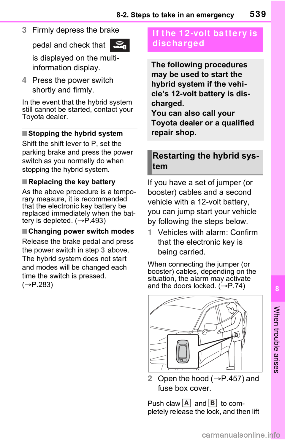
1 Vehicles with alarm: Confirm
that the electronic key is
being carried.
When connecting the jumper (or
booster) cables, depending on the
situation, the alarm may activate
and the doors locked. ( P.74)
2 Open the hood ( P.457) and
fuse box cover.
Push claw and to com-
pletely release the lock, and then lift
If the 12-volt battery is
discharged
The following procedures
may be used to start the
hybrid system if the vehi-
cle’s 12-volt battery is dis-
charged.
You can also call your
Toyota dealer or a qualified
repair shop.
Restarting the hybrid sys-
tem
AB
Page 540 of 616

5408-2. Steps to take in an emergency
up the cover.3Open the exclusive jump
starting terminal cover.
4 Connect a positive jumper cable clamp to on your vehicle and
connect the clamp on the other end of the positive cable to on
the second vehicle. Then, connect a negative cable clamp to
on the second vehicle and connect the clamp at the other end of
the negative cable to .
Exclusive jump starting terminal (your vehicle)
Positive (+) battery terminal (second vehicle)
Negative (-) battery term inal (second vehicle)
Solid, stationary, unpainted metallic point away from the exclu -
sive jump starting terminal and any moving parts as shown in th e
illustration
5 Start the engine of the sec-
ond vehicle. Increase the
engine speed slightly and maintain at that level for
approximately 5 minutes to
A
B
C
D
A
B
C
D