display TOYOTA RAV4 PRIME 2021 Owners Manual
[x] Cancel search | Manufacturer: TOYOTA, Model Year: 2021, Model line: RAV4 PRIME, Model: TOYOTA RAV4 PRIME 2021Pages: 618, PDF Size: 24.18 MB
Page 477 of 618
4777-3. Do-it-yourself maintenance
7
Maintenance and care
“Vehicle Settings”, and then
press and hold .
4 Press or of the meter
control switches and select
“TPWS”, and then press .
5 Press or of the meter
control switches and select
“Identify Wheel”. Then press
and hold until the tire
pressure warning light starts
slowly blinking 3 times.
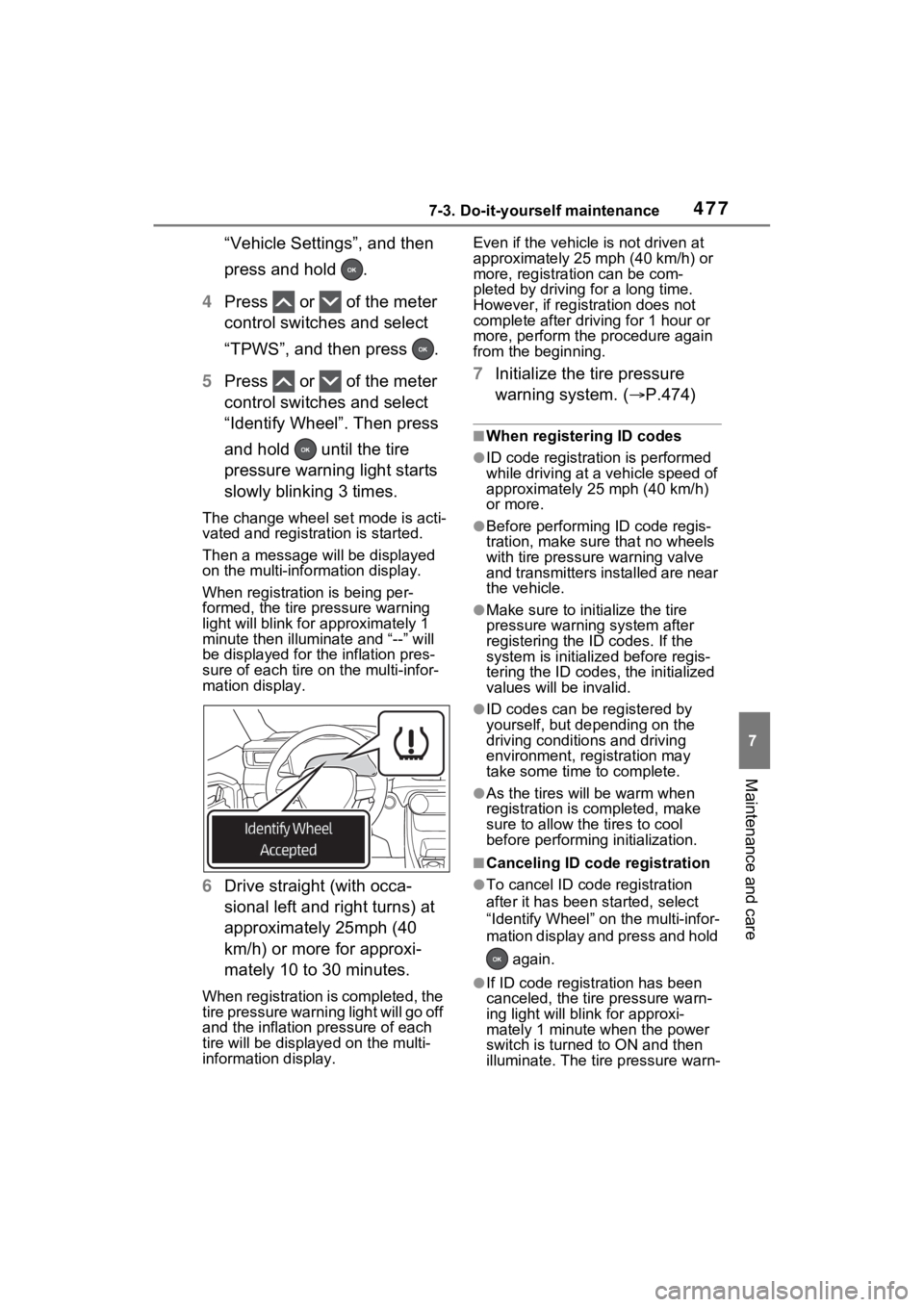
The change wheel set mode is acti-
vated and registration is started.
Then a message w ill be displayed
on the multi-info rmation display.
When registration is being per-
formed, the tire pressure warning
light will blink for approximately 1
minute then illumi nate and “--” will
be displayed for the inflation pres-
sure of each tire on the multi-infor-
mation display.
6 Drive straight (with occa-
sional left and right turns) at
approximately 25mph (40
km/h) or more for approxi-
mately 10 to 30 minutes.
When registration is completed, the
tire pressure warning light will go off
and the inflation pressure of each
tire will be displayed on the multi-
information display. Even if the vehicle
is not driven at
approximately 25 mph (40 km/h) or
more, registration can be com-
pleted by driving for a long time.
However, if registr ation does not
complete after driving for 1 hour or
more, perform the p rocedure again
from the beginning.
7 Initialize the tire pressure
warning system. ( P.474)
■When registering ID codes
●ID code registrati on is performed
while driving at a vehicle speed of
approximately 25 mph (40 km/h)
or more.
●Before performing ID code regis-
tration, make sure that no wheels
with tire pressure warning valve
and transmitters installed are near
the vehicle.
●Make sure to initi alize the tire
pressure warning system after
registering the ID codes. If the
system is initialized before regis-
tering the ID codes , the initialized
values will be invalid.
●ID codes can be registered by
yourself, but depending on the
driving conditions and driving
environment, registration may
take some time to complete.
●As the tires will be warm when
registration is completed, make
sure to allow the tires to cool
before performin g initialization.
■Canceling ID code registration
●To cancel ID code registration
after it has been started, select
“Identify Wheel” on the multi-infor-
mation display and press and hold
again.
●If ID code registration has been
canceled, the tire pressure warn-
ing light will blin k for approxi-
mately 1 minute when the power
switch is turned to ON and then
illuminate. The tire pressure warn-
Page 479 of 618
4797-3. Do-it-yourself maintenance
7
Maintenance and care
registered wheel set is possi-
ble, mixing between these
wheel sets is not supported.
■How to change between
wheel sets
1 Have the vehicle fitted with
the preferred wheel set.
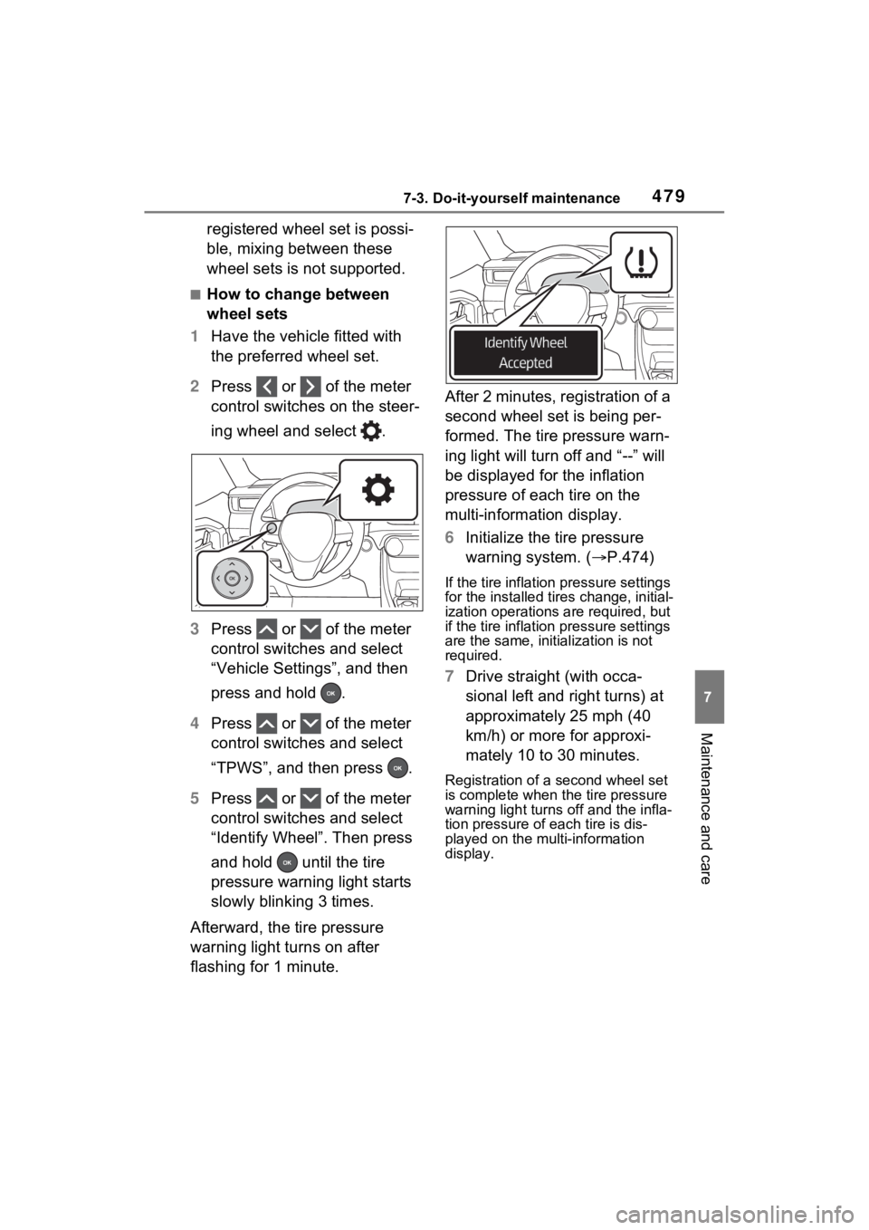
2 Press or of the meter
control switches on the steer-
ing wheel and select .
3 Press or of the meter
control switches and select
“Vehicle Settings”, and then
press and hold .
4 Press or of the meter
control switches and select
“TPWS”, and then press .
5 Press or of the meter
control switches and select
“Identify Wheel”. Then press
and hold until the tire
pressure warning light starts
slowly blinking 3 times.
Afterward, the tire pressure
warning light turns on after
flashing for 1 minute. After 2 minutes, registration of a
second wheel set is being per-
formed. The tire pressure warn-
ing light will turn off and “--” will
be displayed for the inflation
pressure of each tire on the
multi-information display.
6
Initialize the tire pressure
warning system. ( P.474)
If the tire inflation pressure settings
for the installed ti res change, initial-
ization operations are required, but
if the tire inflation pressure settings
are the same, init ialization is not
required.
7 Drive straight (with occa-
sional left and right turns) at
approximately 25 mph (40
km/h) or more for approxi-
mately 10 to 30 minutes.
Registration of a second wheel set
is complete when the tire pressure
warning light turns off and the infla-
tion pressure of each tire is dis-
played on the multi-information
display.
Page 480 of 618
4807-3. Do-it-yourself maintenance
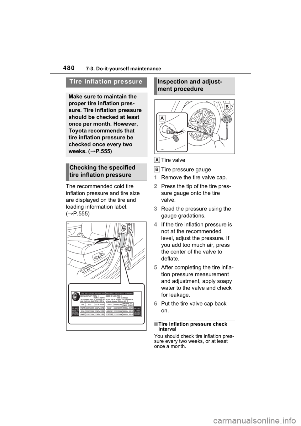
The recommended cold tire
inflation pressure and tire size
are displayed on the tire and
loading information label.
(P.555) Tire valve
Tire pressure gauge
1 Remove the tire valve cap.
2 Press the tip of the tire pres-
sure gauge onto the tire
valve.
3 Read the pressure using the
gauge gradations.
4 If the tire inflation pressure is
not at the recommended
level, adjust the pressure. If
you add too much air, press
the center of the valve to
deflate.
5 After completing the tire infla-
tion pressure measurement
and adjustment, apply soapy
water to the valve and check
for leakage.
6 Put the tire valve cap back
on.
■Tire inflation pressure check
interval
You should check tire inflation pres-
sure every two week s, or at least
once a month.
Tire inflation pressure
Make sure to maintain the
proper tire inflation pres-
sure. Tire inflation pressure
should be checked at least
once per month. However,
Toyota recommends that
tire inflation pressure be
checked once every two
weeks. ( P.555)
Checking the specified
tire inflation pressure
Inspection and adjust-
ment procedure
A
B
Page 486 of 618
4867-3. Do-it-yourself maintenance
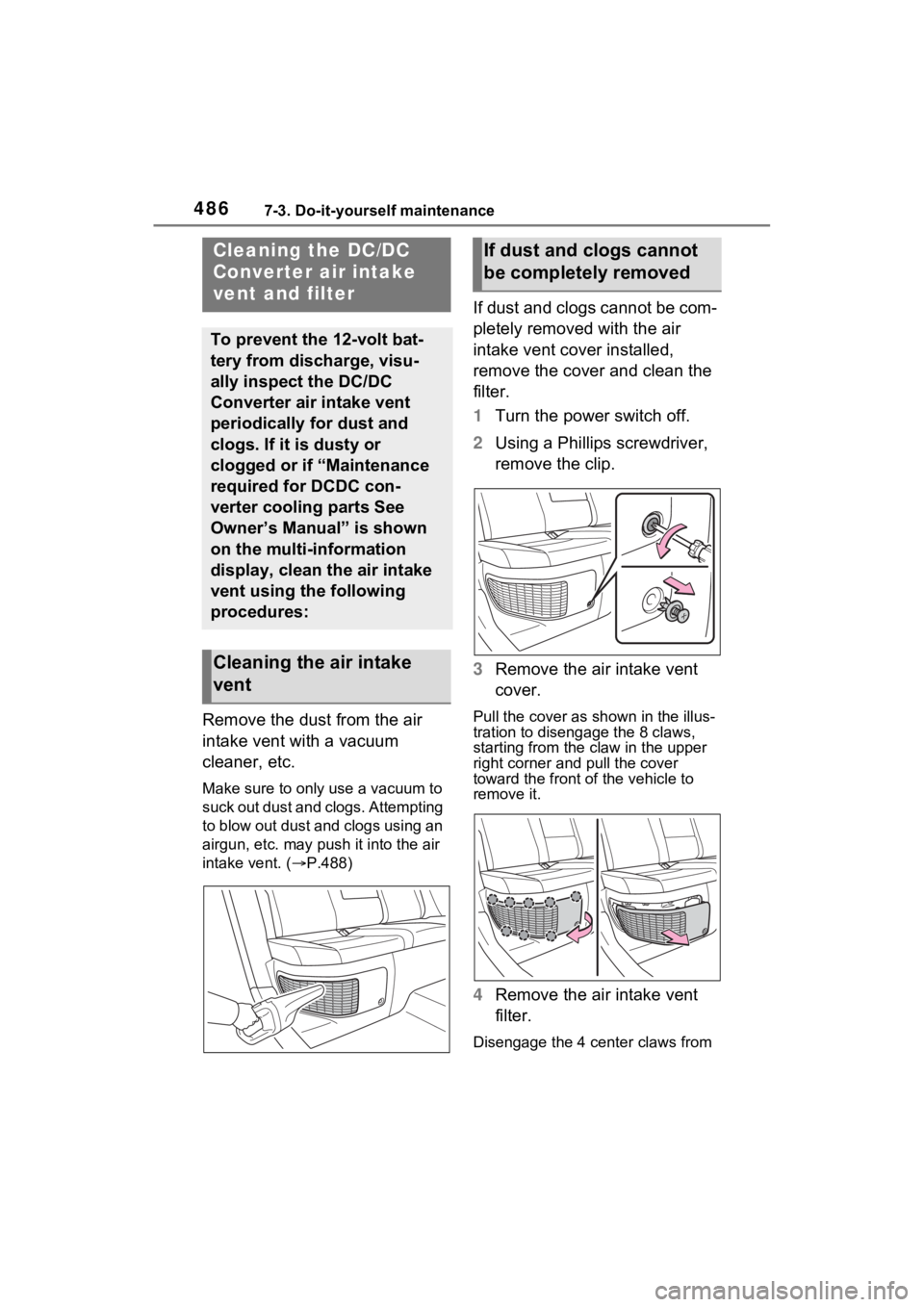
Remove the dust from the air
intake vent with a vacuum
cleaner, etc.
Make sure to only use a vacuum to
suck out dust and clogs. Attempting
to blow out dust and clogs using an
airgun, etc. may push it into the air
intake vent. (P.488)
If dust and clogs cannot be com-
pletely removed with the air
intake vent cover installed,
remove the cover and clean the
filter.
1 Turn the power switch off.
2 Using a Phillips screwdriver,
remove the clip.
3 Remove the air intake vent
cover.
Pull the cover as shown in the illus-
tration to disengage the 8 claws,
starting from the claw in the upper
right corner and pull the cover
toward the front of the vehicle to
remove it.
4 Remove the air intake vent
filter.
Disengage the 4 center claws from
Cleaning the DC/DC
Converter air intake
vent and filter
To prevent the 12-volt bat-
tery from discharge, visu-
ally inspect the DC/DC
Converter air intake vent
periodically for dust and
clogs. If it is dusty or
clogged or if “Maintenance
required for DCDC con-
verter cooling parts See
Owner’s Manual” is shown
on the multi-information
display, clean the air intake
vent using the following
procedures:
Cleaning the air intake
vent
If dust and clogs cannot
be completely removed
Page 488 of 618
4887-3. Do-it-yourself maintenance
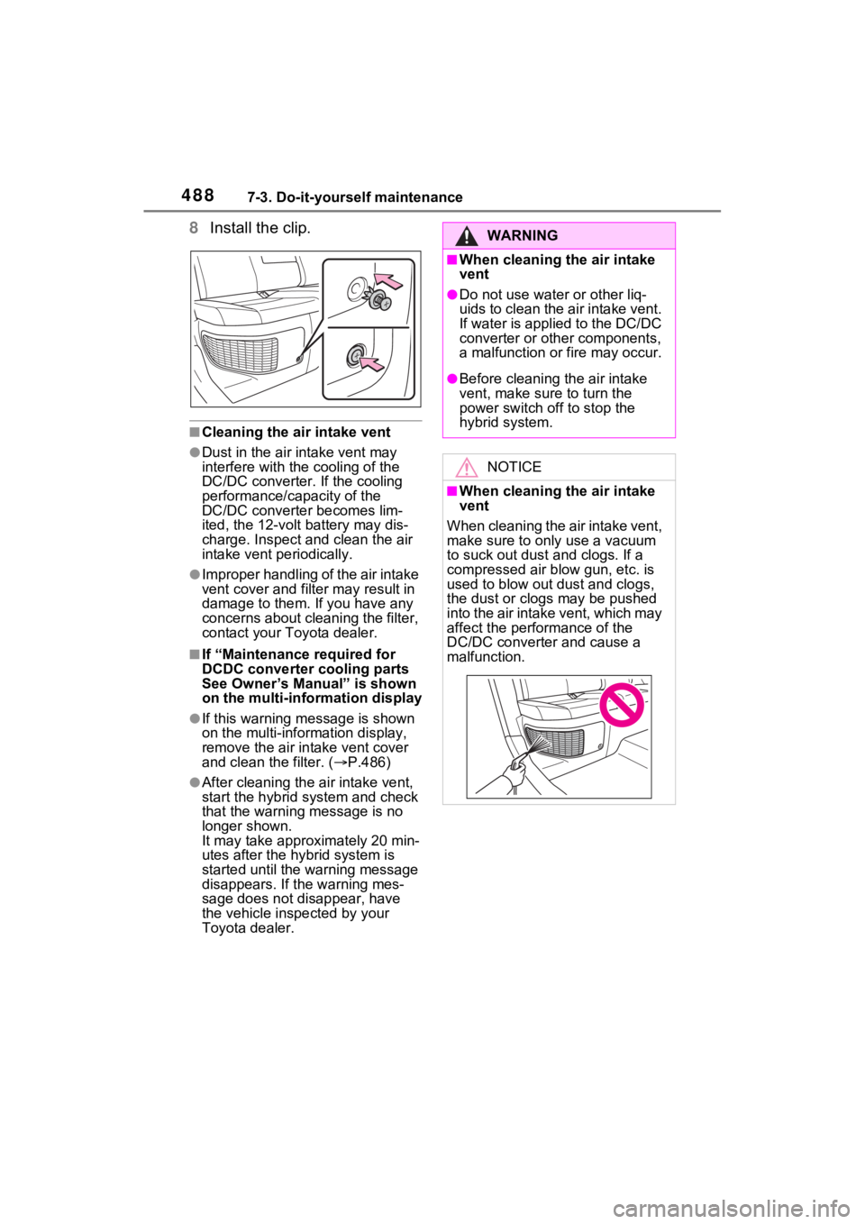
8Install the clip.
■Cleaning the ai r intake vent
●Dust in the air intake vent may
interfere with the cooling of the
DC/DC converter. If the cooling
performance/capacity of the
DC/DC converte r becomes lim-
ited, the 12-volt battery may dis-
charge. Inspect and clean the air
intake vent periodically.
●Improper handling of the air intake
vent cover and filt er may result in
damage to them. If you have any
concerns about cleaning the filter,
contact your Toyota dealer.
■If “Maintenance required for
DCDC converter cooling parts
See Owner’s Manual” is shown
on the multi-information display
●If this warning m essage is shown
on the multi-information display,
remove the air in take vent cover
and clean the filter. ( P.486)
●After cleaning the air intake vent,
start the hybrid system and check
that the warning message is no
longer shown.
It may take approximately 20 min-
utes after the hybrid system is
started until the warning message
disappears. If the warning mes-
sage does not disappear, have
the vehicle inspected by your
Toyota dealer.
WARNING
■When cleaning the air intake
vent
●Do not use water or other liq-
uids to clean the air intake vent.
If water is applied to the DC/DC
converter or other components,
a malfunction or fire may occur.
●Before cleaning the air intake
vent, make sure to turn the
power switch off to stop the
hybrid system.
NOTICE
■When cleaning the air intake
vent
When cleaning the air intake vent,
make sure to onl y use a vacuum
to suck out dust and clogs. If a
compressed air blow gun, etc. is
used to blow out dust and clogs,
the dust or clog s may be pushed
into the air intake vent, which may
affect the perfor mance of the
DC/DC converter and cause a
malfunction.
Page 489 of 618
4897-3. Do-it-yourself maintenance
7
Maintenance and care
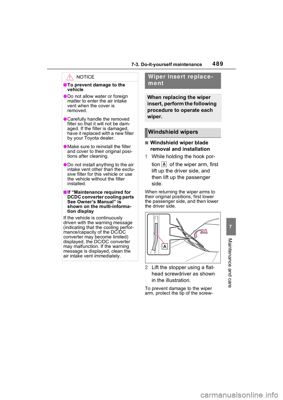
■Windshield wiper blade
removal and installation
1 While holding the hook por-
tion of the wiper arm, first
lift up the driver side, and
then lift up the passenger
side.
When returning the wiper arms to
their original positions, first lower
the passenger side, and then lower
the driver side.
2Lift the stopper using a flat-
head screwdriver as shown
in the illustration.
To prevent damage to the wiper
arm, protect the tip of the screw-
NOTICE
■To prevent damage to the
vehicle
●Do not allow water or foreign
matter to enter t he air intake
vent when the cover is
removed.
●Carefully handle the removed
filter so that i t will not be dam-
aged. If the filter is damaged,
have it replaced with a new filter
by your Toyota dealer.
●Make sure to reinstall the filter
and cover to their original posi-
tions after cleaning.
●Do not install anything to the air
intake vent other than the exclu-
sive filter for this vehicle or use
the vehicle without the filter
installed.
■If “Maintenance required for
DCDC converter cooling parts
See Owner’s Manual” is
shown on the multi-informa-
tion display
If the vehicle is continuously
driven with the warning message
(indicating that the cooling perfor-
mance/capacity of the DC/DC
converter may become limited)
displayed, the DC/DC converter
may malfunction. If the warning
message is displayed, clean the
air intake vent immediately.
Wiper insert replace-
ment
When replacing the wiper
insert, perform the following
procedure to operate each
wiper.
Windshield wipers
A
Page 508 of 618
5088-2. Steps to take in an emergency
The following may indicate a
problem with your transmission.
Contact your Toyota dealer or
commercial towing service
before towing.
The hybrid system warning
message is shown on the
multi-information display and
the vehicle does not move.
The vehicle makes an abnor-
mal sound.
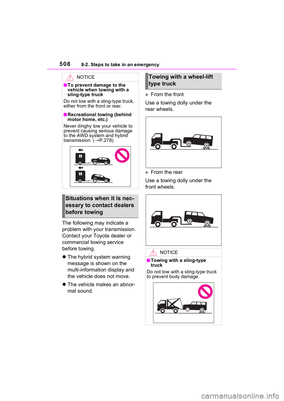
From the front
Use a towing dolly under the
rear wheels.
From the rear
Use a towing dolly under the
front wheels.
NOTICE
■To prevent damage to the
vehicle when towing with a
sling-type truck
Do not tow with a sling-type truck,
either from the front or rear.
■Recreational towing (behind
motor home, etc.)
Never dinghy tow your vehicle to
prevent causing serious damage
to the AWD system and hybrid
transmission. ( P.278)
Situations when it is nec-
essary to contact dealers
before towing
Towing with a wheel-lift
type truck
NOTICE
■Towing with a sling-type
truck
Do not tow with a sling-type truck
to prevent body damage.
Page 511 of 618
5118-2. Steps to take in an emergency
8
When trouble arises
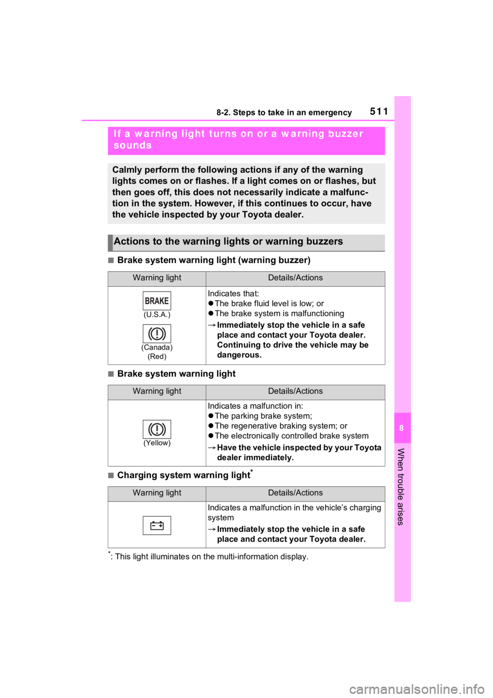
■Brake system warning light (warning buzzer)
■Brake system warning light
■Charging system warning light*
*: This light illuminat es on the multi-information display.
If a warning light turns on or a warning buzzer
sounds
Calmly perform the following actions if any of the warning
lights comes on or flashes. If a light comes on or flashes, but
then goes off, this does not necessarily indicate a malfunc-
tion in the system. However, if this continues to occur, have
the vehicle inspected by your Toyota dealer.
Actions to the warning lights or warning buzzers
Warning lightDetails/Actions
(U.S.A.)
(Canada) (Red)
Indicates that:
The brake fluid level is low; or
The brake system is malfunctioning
Immediately stop the vehicle in a safe
place and contact your Toyota dealer.
Continuing to drive the vehicle may be
dangerous.
Warning lightDetails/Actions
(Yellow)
Indicates a malfunction in:
The parking brake system;
The regenerative braking system; or
The electronically controlled brake system
Have the vehicle inspected by your Toyota
dealer immediately.
Warning lightDetails/Actions
Indicates a malfunction in the vehicle’s charging
system
Immediately stop the vehicle in a safe
place and contact your Toyota dealer.
Page 512 of 618
5128-2. Steps to take in an emergency
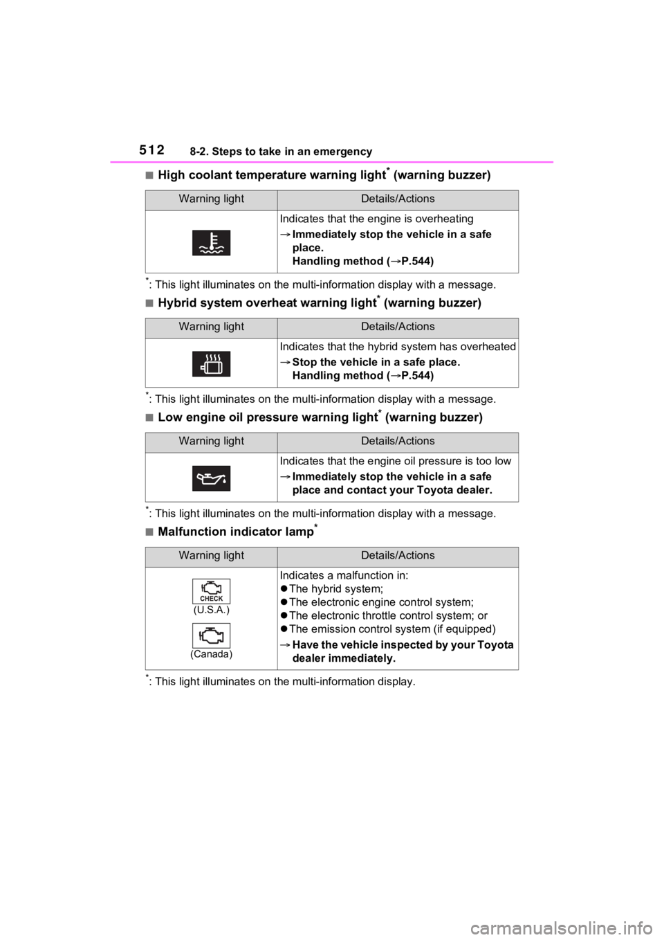
■High coolant temperature warning light* (warning buzzer)
*: This light illuminates on the mu lti-information display with a message.
■Hybrid system overheat warning light* (warning buzzer)
*: This light illuminates on the mu lti-information display with a message.
■Low engine oil pressure warning light* (warning buzzer)
*: This light illuminates on the mu lti-information display with a message.
■Malfunction indicator lamp*
*: This light illuminat es on the multi-information display.
Warning lightDetails/Actions
Indicates that the engine is overheating
Immediately stop the vehicle in a safe
place.
Handling method ( P.544)
Warning lightDetails/Actions
Indicates that the hybrid system has overheated
Stop the vehicle in a safe place.
Handling method ( P.544)
Warning lightDetails/Actions
Indicates that the engine oil pressure is too low
Immediately stop the vehicle in a safe
place and contact your Toyota dealer.
Warning lightDetails/Actions
(U.S.A.)
(Canada)
Indicates a malfunction in:
The hybrid system;
The electronic engi ne control system;
The electronic throttle control system; or
The emission control s ystem (if equipped)
Have the vehicle inspected by your Toyota
dealer immediately.
Page 513 of 618
5138-2. Steps to take in an emergency
8
When trouble arises
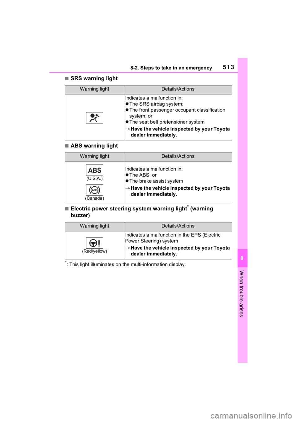
■SRS warning light
■ABS warning light
■Electric power steering system warning light* (warning
buzzer)
*: This light illuminat es on the multi-information display.
Warning lightDetails/Actions
Indicates a malfunction in:
The SRS airbag system;
The front passenger o ccupant classification
system; or
The seat belt pretensioner system
Have the vehicle inspected by your Toyota
dealer immediately.
Warning lightDetails/Actions
(U.S.A.)
(Canada)
Indicates a malfunction in:
The ABS; or
The brake assist system
Have the vehicle inspected by your Toyota
dealer immediately.
Warning lightDetails/Actions
(Red/yellow)
Indicates a malfunction in the EPS (Electric
Power Steeri ng) system
Have the vehicle inspected by your Toyota
dealer immediately.