warning light TOYOTA RAV4 PRIME 2022 Owner's Manual
[x] Cancel search | Manufacturer: TOYOTA, Model Year: 2022, Model line: RAV4 PRIME, Model: TOYOTA RAV4 PRIME 2022Pages: 624, PDF Size: 24.01 MB
Page 126 of 624
1262-2. Charging
WARNING
■When charging
Observe the following precau-
tions.
Failure to do so may cause an
unexpected accident, resulting in
death or serious injury.
●Connect to a power source suit-
able for charging. ( P.111)
●Check that the AC charging
cable, plug and outlet are free of
foreign matter.
●Before charging, check that the
AC charging inlet is not
deformed, damaged or cor-
roded, and check that the inlet
is free of foreign matter such as
dirt, snow and ice.
If there is dirt or dust in these
areas, remove completely
before inserting the charging
connector.
●Do not get the terminals of the
AC charging inlet wet.
●Only use outlets where the plug
can be securely inserted.
●Do not bundle or wind the AC
charging cable while charging,
as doing so may result in over-
heating.
●Do not touch the terminals of
the charging connector and AC
charging inlet with a sharp metal
objects (needles etc.) or hands,
or short them with foreign
objects.
●When charging outdoors, make
sure to connect to a weather-
proof outlet for outdoor use.
Ensure the weatherproof outlet
cover closes completely. If the
weatherproof outlet cover can-
not be closed, install a weather-
proof outlet cover that will close.
●In order to stop charging at the
charging station, follow the
instructions of the charger.
●If any heat, smoke, odors, noise
or other abnormalities are
noticed during charging, stop
charging immediately.
●Do not insert the plug if the out-
let is submerge d in water or
snow.
●When charging while it is raining
or snowing, do not connect or
disconnect the plug if your
hands are wet. Also, do not get
the plug or outlet wet.
●Do not charge the vehicle
during a lightning storm.
●Prevent the AC charging cable
from being caught in the door or
back door.
●Do not let the wheels on the AC
charging cable, plug, charging
connector and CCID (Charging
Circuit Interru pting Device).
●Firmly insert the plug into the
outlet.
●Do not use an extension cord
and converting adaptor.
●Close the hood before using the
charging system. The cooling
fan may start operating sud-
denly. Touching or getting close
to rotating parts such as the fan
may cause your hands or
clothes (especially a necktie or
scarf) to becom e caught and
result in a serious injury.
●After connecting the charging
cable, confirm that it is not
wound around anything.
Page 129 of 624
1292-2. Charging
2
Plug-in hybrid system
5Remove the plug from the
outlet when the charging
equipment will not be used
for a prolonged period of
time.
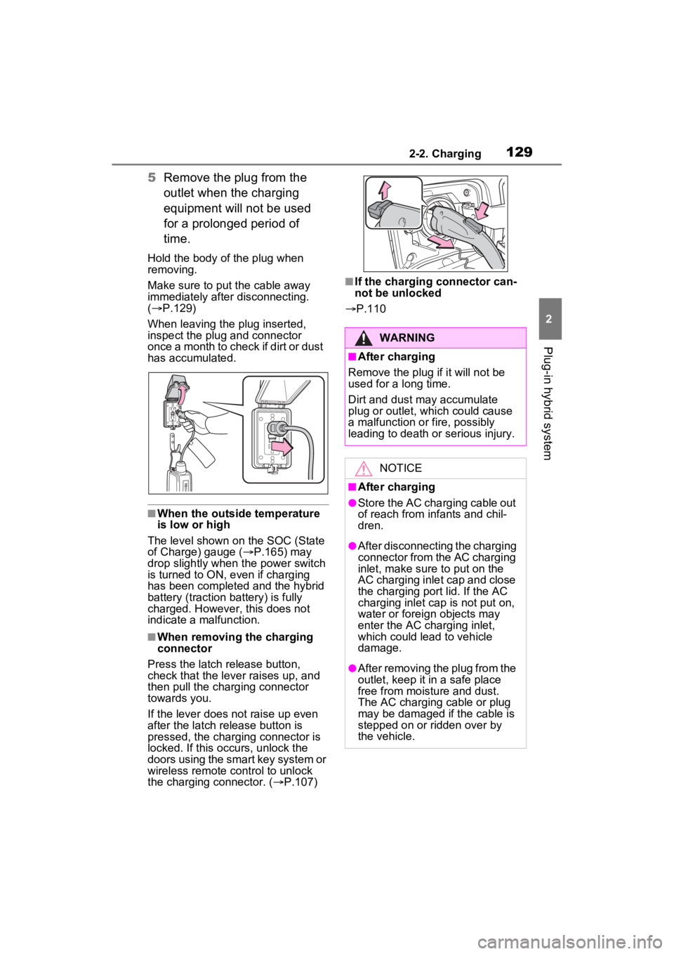
Hold the body of the plug when
removing.
Make sure to put the cable away
immediately afte r disconnecting.
( P.129)
When leaving the plug inserted,
inspect the plug and connector
once a month to check if dirt or dust
has accumulated.
■When the outside temperature
is low or high
The level shown on the SOC (State
of Charge) gauge ( P.165) may
drop slightly when the power switch
is turned to ON, e ven if charging
has been completed and the hybrid
battery (traction battery) is fully
charged. However, this does not
indicate a malfunction.
■When removing the charging
connector
Press the latch release button,
check that the lever raises up, and
then pull the charging connector
towards you.
If the lever does not raise up even
after the latch release button is
pressed, the charging connector is
locked. If this occurs, unlock the
doors using the smart key system or
wireless remote control to unlock
the charging connector. ( P.107)
■If the charging connector can-
not be unlocked
P.110
WARNING
■After charging
Remove the plug if it will not be
used for a long time.
Dirt and dust may accumulate
plug or outlet, which could cause
a malfunction or fire, possibly
leading to death or serious injury.
NOTICE
■After charging
●Store the AC charging cable out
of reach from infants and chil-
dren.
●After disconnecting the charging
connector from the AC charging
inlet, make sure to put on the
AC charging inlet cap and close
the charging port lid. If the AC
charging inlet cap is not put on,
water or foreign objects may
enter the AC cha rging inlet,
which could lead to vehicle
damage.
●After removing the plug from the
outlet, keep it in a safe place
free from moisture and dust.
The AC charging cable or plug
may be damaged if the cable is
stepped on or ridden over by
the vehicle.
Page 145 of 624
1452-2. Charging
2
Plug-in hybrid system
To stop “My Room Mode”, turn
the power switch off.
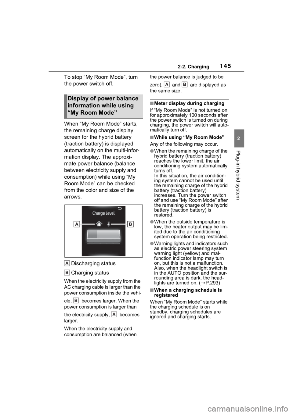
When “My Room Mode” starts,
the remaining charge display
screen for the hybrid battery
(traction battery) is displayed
automatically on the multi-infor-
mation display. The approxi-
mate power balance (balance
between electricity supply and
consumption) while using “My
Room Mode” can be checked
from the color and size of the
arrows.Discharging status
Charging status
When the electricity supply from the
AC charging cable is larger than the
power consumption inside the vehi-
cle, becomes larger. When the
power consumption is larger than
the electricity su pply, becomes
larger.
When the electricity supply and
consumption are balanced (when the power balance is judged to be
zero), and are displayed as
the same size.
■Meter display during charging
If “My Room Mode” is not turned on
for approximately 100 seconds after
the power switch is turned on during
charging, the power switch will auto-
matically turn off.
■While using “My Room Mode”
Any of the following may occur.
●When the remaining charge of the
hybrid battery (traction battery)
reaches the lowe r limit, the air
conditioning system automatically
turns off.
In this situation, the air condition-
ing system cannot be used until
the remaining charge of the hybrid
battery (traction battery)
increases. Turn the power switch
off and use “My Room Mode” after
the remaining charge of the hybrid
battery (traction battery) is
restored.
●When the outside temperature is
low, the heater ou tput may be lim-
ited due to the air conditioning
system operation being restricted.
●Warning lights and indicators such
as electric power steering system
warning light (yellow) and mal-
function indicator lamp may turn
on, but this is no t a malfunction.
Also, when the headlight switch is
in the AUTO position and the sur-
rounding area is dark, the head-
lights are turned on. ( P.293)
■When a charging schedule is
registered
When “My Room Mode” starts while
the charging schedule is on
standby, charging schedules are
ignored and charging starts.
Display of power balance
information while using
“My Room Mode”
A
B
B
A
AB
Page 159 of 624
159
3
3
Vehicle status information and indicators
Vehicle status informa-tion and indicators
3-1. Instrument cluster
Warning lights and indica-tors ............................ 160
Gauges and meters .... 165
Multi-information display .................................. 170
Head-up display .......... 182
Energy monitor/consump- tion screen................. 187
Page 160 of 624
1603-1. Instrument cluster
3-1.Instrument cluster
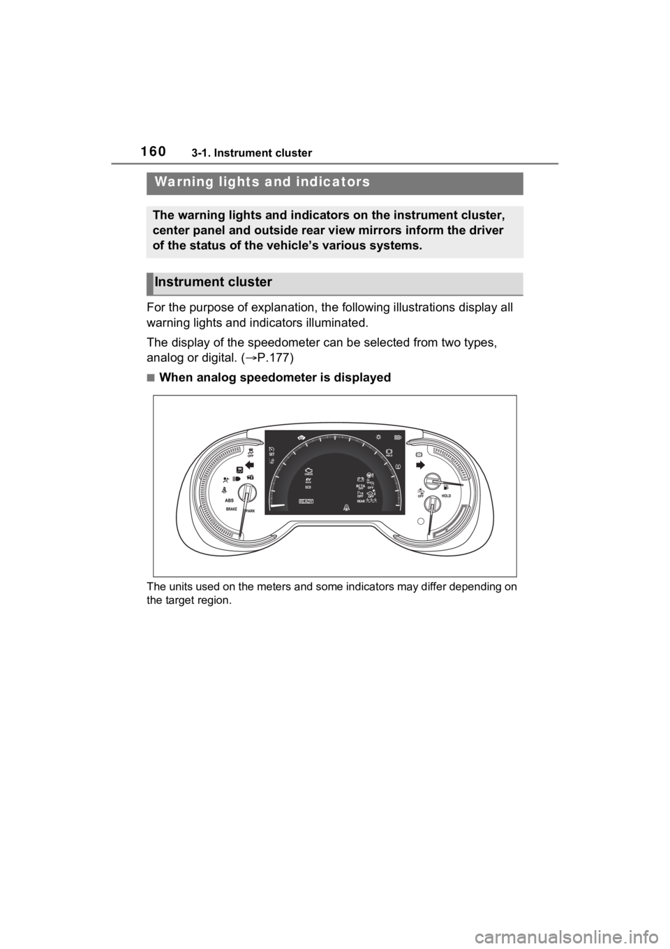
For the purpose of explanation, the following illustrations display all
warning lights and indicators illuminated.
The display of the speedometer can be selected from two types,
analog or digital. ( P.177)
■When analog speedometer is displayed
The units used on the meters and some indicators may differ dep ending on
the target region.
Warning lights and indicators
The warning lights and indicators on the instrument cluster,
center panel and outside rear view mirrors inform the driver
of the status of the vehicle’s various systems.
Instrument cluster
Page 161 of 624
1613-1. Instrument cluster
3
Vehicle status information and indicators
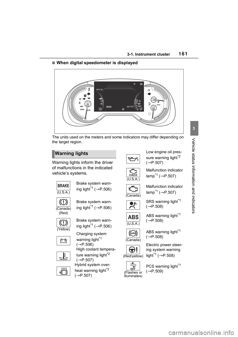
■When digital speedometer is displayed
The units used on the meters and some indicators may differ depending on
the target region.
Warning lights inform the driver
of malfunctions in the indicated
vehicle’s systems.
Warning lights
(U.S.A.)
Brake system warn-
ing light
*1 ( P.506)
(Canada)
(Red)
Brake system warn-
ing light
*1 ( P.506)
(Yellow)
Brake system warn-
ing light
*1 ( P.506)
Charging system
warning light
*1
( P.506)
High coolant tempera-
ture warning light
*2
( P.507)
Hybrid system over-
heat warning light
*2
( P.507)
Low engine oil pres-
sure warning light
*2
( P.507)
(U.S.A.)
Malfunction indicator
lamp
*1 ( P.507)
(Canada)
Malfunction indicator
lamp
*1 ( P.507)
SRS warning light
*1
( P.508)
(U.S.A.)
ABS warning light*1
( P.508)
(Canada)
ABS warning light*1
( P.508)
(Red/yellow)
Electric power steer-
ing system warning
light
*1 ( P.508)
(Flashes or
illuminates)
PCS warning light*1
( P.509)
Page 162 of 624
1623-1. Instrument cluster
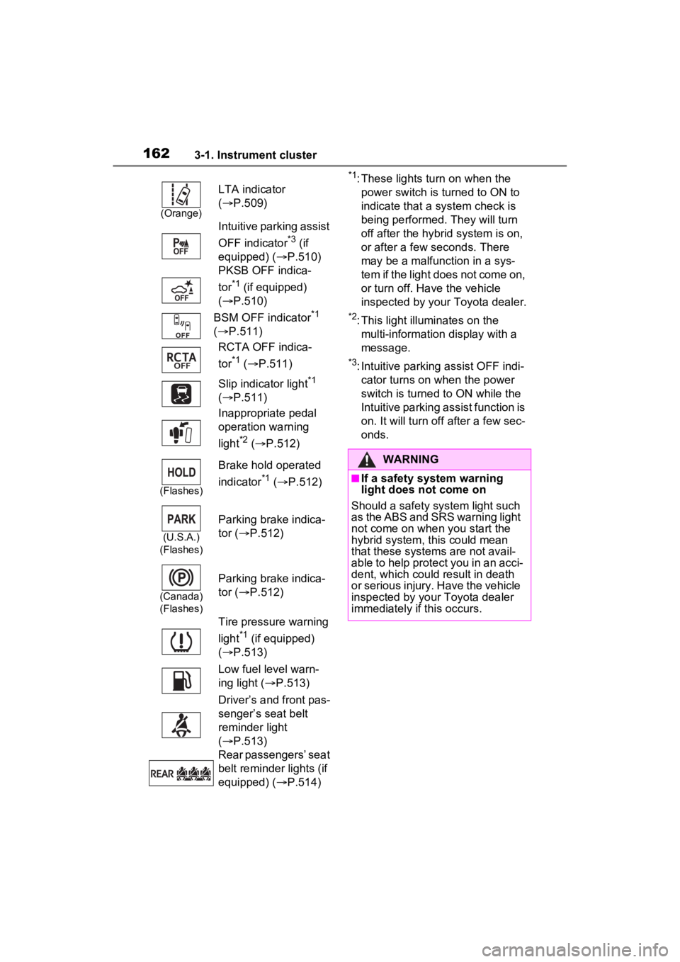
*1: These lights turn on when the
power switch is turned to ON to
indicate that a system check is
being performed. They will turn
off after the hybrid system is on,
or after a few seconds. There
may be a malfunction in a sys-
tem if the light does not come on,
or turn off. Have the vehicle
inspected by your Toyota dealer.
*2: This light illuminates on the multi-information display with a
message.
*3: Intuitive parking assist OFF indi-cator turns on wh en the power
switch is turned t o ON while the
Intuitive parking assist function is
on. It will turn off after a few sec-
onds.
(Orange)
LTA indicator
( P.509)
Intuitive parking assist
OFF indicator
*3 (if
equipped) ( P.510)
PKSB OFF indica-
tor
*1 (if equipped)
( P.510)
BSM OFF indicator
*1
( P.511)
RCTA OFF indica-
tor
*1 ( P.511)
Slip indicator light
*1
( P.511)
Inappropriate pedal
operation warning
light
*2 ( P.512)
(Flashes)
Brake hold operated
indicator
*1 ( P.512)
(U.S.A.)
(Flashes)
Parking brake indica-
tor ( P.512)
(Canada)
(Flashes)
Parking brake indica-
tor ( P.512)
Tire pressure warning
light
*1 (if equipped)
( P.513)
Low fuel level warn-
ing light ( P.513)
Driver’s and front pas-
senger’s seat belt
reminder light
( P.513)
Rear passengers’ seat
belt reminder lights (if
equipped) ( P.514)
WARNING
■If a safety system warning
light does not come on
Should a safety system light such
as the ABS and SRS warning light
not come on when you start the
hybrid system, this could mean
that these system s are not avail-
able to help protect you in an acci-
dent, which could result in death
or serious injury. Have the vehicle
inspected by your Toyota dealer
immediately if this occurs.
Page 163 of 624

1633-1. Instrument cluster
3
Vehicle status information and indicators
The indicators inform the driver
of the operating state of the
vehicle’s various systems.
Indicators
Turn signal indicator
( P.286)
(U.S.A.)
Headlight indicator
( P.293)
(Canada)
Tail light indicator
( P.293)
Headlight high beam
indicator ( P.295)
Automatic High Beam
indicator ( P.296)
Smart key system
indicator
*1 ( P.277)
Cruise control indica-
tor ( P.334)
Dynamic radar cruise
control indicator
( P.334)
Cruise control “SET”
indicator ( P.334)
LTA indicator
*2
( P.326)
Intuitive parking assist
OFF indicator
*3, 4 (if
equipped) ( P.357)
PKSB OFF indicator
*3,
5
(if equipped)
( P.365)
(Flashes)
Slip indicator light*5
( P.376)
VSC OFF indicator*3,
5
( P.377)
PCS warning light
*3, 5
( P.315)
BSM outside rear view
mirror indicators
*5, 6
( P.346)
BSM OFF indicator
*3,
5
( P.346)
RCTA OFF indica-
tor
*3, 5 ( P.346)
Brake hold standby
indicator
*5 ( P.291)
Brake hold operated
indicator
*5 ( P.291)
Security indicator
( P.71, 72)
“READY” indicator
( P.277)
Low outside tempera-
ture indicator
*7
( P.168)
EV indicator ( P.82)
(U.S.A.)
Parking brake indica-
tor ( P.287)
(Canada)
Parking brake indica-
tor (P.287)
EV drive mode indica-
tor
*8 ( P.78)
AUTO EV/HV mode
indicator
*8 ( P.78)
HV drive mode indica-
tor
*8 ( P.78)
Page 169 of 624
1693-1. Instrument cluster
3
Vehicle status information and indicators
●Displays the outside temperature
within the range of -40°F (-40°C)
to 122°F (50°C).
●When the outside temperature is
approximately 37°F (3°C) or
lower, the indicator will flash
for approximately 10 seconds,
then stay on.
■Liquid crystal display
P.171
■Customization
Settings (e. g. meter display) can be
changed on the screen of the
multi-informat ion display. (P.177)
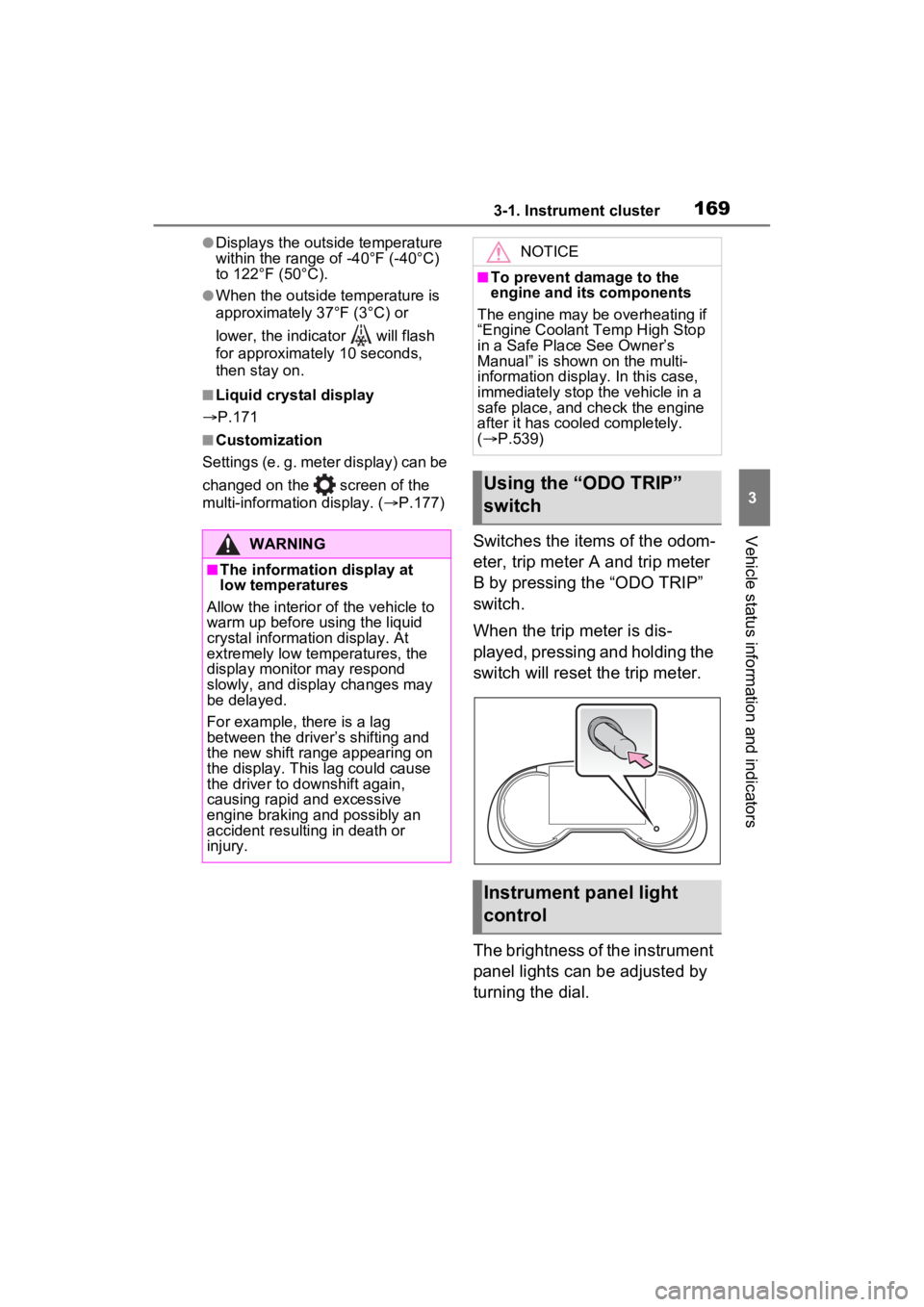
Switches the items of the odom-
eter, trip meter A and trip meter
B by pressing the “ODO TRIP”
switch.
When the trip meter is dis-
played, pressing and holding the
switch will reset the trip meter.
The brightness of the instrument
panel lights can be adjusted by
turning the dial.WARNING
■The information display at
low temperatures
Allow the interior of the vehicle to
warm up before u sing the liquid
crystal informat ion display. At
extremely low temperatures, the
display monitor may respond
slowly, and display changes may
be delayed.
For example, there is a lag
between the driver’s shifting and
the new shift range appearing on
the display. This lag could cause
the driver to downshift again,
causing rapid and excessive
engine braking and possibly an
accident resulting in death or
injury.
NOTICE
■To prevent damage to the
engine and its components
The engine may be overheating if
“Engine Coolant Temp High Stop
in a Safe Place See Owner’s
Manual” is shown on the multi-
information displa y. In this case,
immediately stop the vehicle in a
safe place, and c heck the engine
after it has cooled completely.
( P.539)
Using the “ODO TRIP”
switch
Instrument panel light
control
Page 171 of 624
1713-1. Instrument cluster
3
Vehicle status information and indicators
Information display area
A variety of information can be dis-
played by selecting a menu icon.
Additionally, warning or sugges-
tion/advice pop-up displays will be
displayed in some situations.
Menu icons ( P.171)
■The multi-information display is
displayed when
The power swit ch is in ON.
■When changing driving mode
Background color of the multi-infor-
mation display is changed following
the selected drivi ng mode or when
Trail Mode is turned on. ( P.372,
374)
■Liquid crystal display
Small spots or light spots may
appear on the display. This phe-
nomenon is character istic of liquid
crystal displays, and there is no
problem continuing to use the dis-
play.
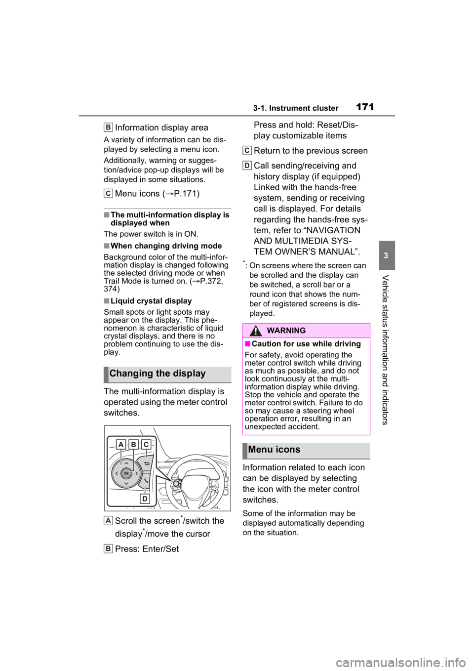
The multi-information display is
operated using the meter control
switches.
Scroll the screen
*/switch the
display
*/move the cursor
Press: Enter/Set Press and hold: Reset/Dis-
play customizable items
Return to the previous screen
Call sending/receiving and
history display (if equipped)
Linked with the hands-free
system, sending or receiving
call is displayed. For details
regarding the hands-free sys-
tem, refer to “NAVIGATION
AND MULTIMEDIA SYS-
TEM OWNER’S MANUAL”.
*: On screens where the screen can
be scrolled and the display can
be switched, a scroll bar or a
round icon that shows the num-
ber of registered screens is dis-
played.
Information related to each icon
can be displayed by selecting
the icon with the meter control
switches.
Some of the information may be
displayed automatically depending
on the situation.
Changing the display
B
C
A
B
�:�$�5�1�,�1�*
■Caution for use while driving
For safety, avoid operating the
meter control switch while driving
as much as possible, and do not
look continuously at the multi-
information display while driving.
Stop the vehicle and operate the
meter control switch. Failure to do
so may cause a steering wheel
operation error, resulting in an
unexpected accident.
Menu icons
C
D