turn signal TOYOTA SEQUOIA HYBRID 2023 User Guide
[x] Cancel search | Manufacturer: TOYOTA, Model Year: 2023, Model line: SEQUOIA HYBRID, Model: TOYOTA SEQUOIA HYBRID 2023Pages: 628, PDF Size: 14.27 MB
Page 222 of 628
2224-2. Driving procedures
Owners Manual_USA_M0C043_en
■Turn signals can be operated
when
The power swit ch is in ON.
■If the indicator flashes faster
than usual
Check that the front or rear turn sig-
nal lights has not burned out.
■If the turn signals stop flashing
before a lane change has been
performed
Operate the lever again.
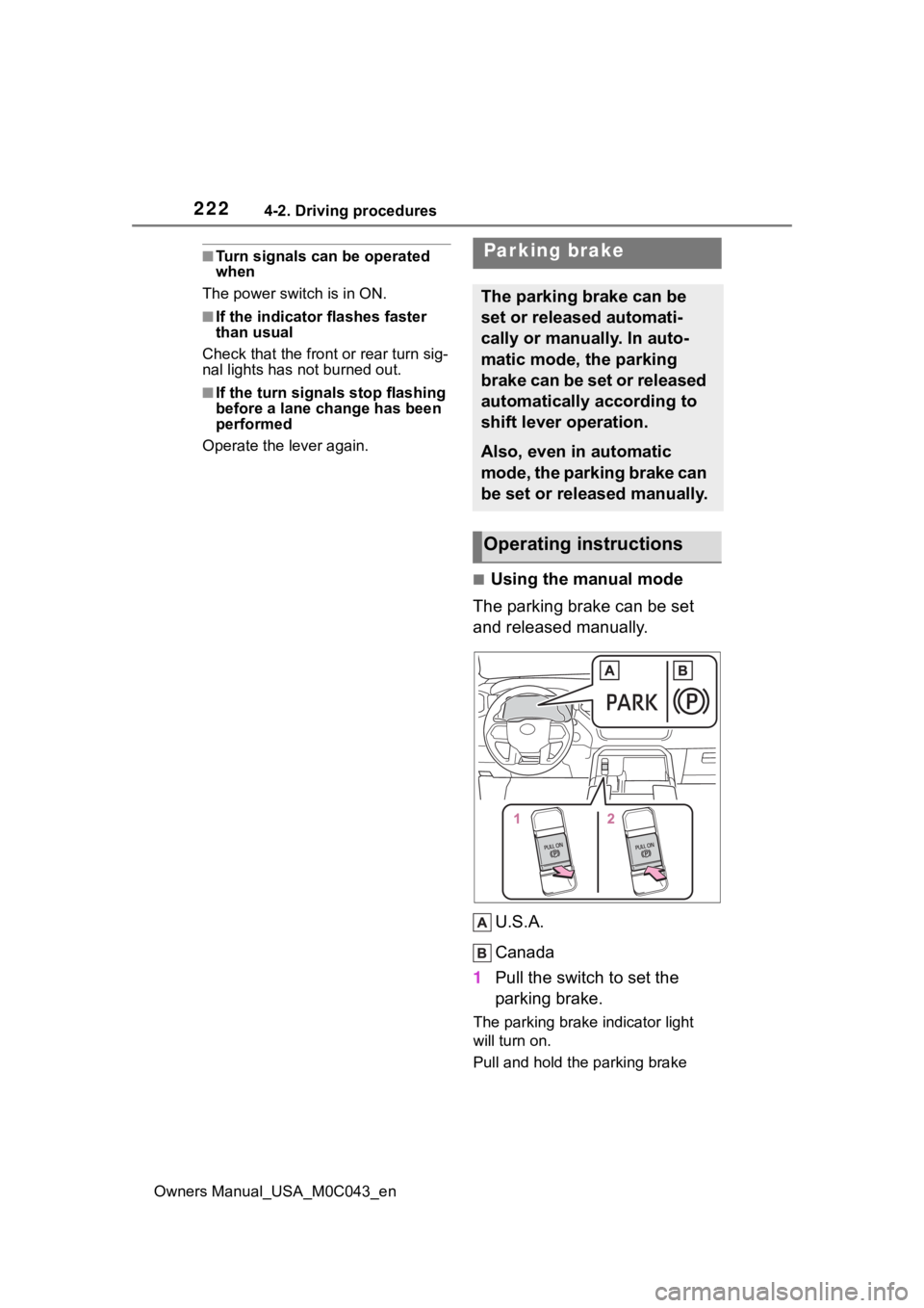
■Using the manual mode
The parking brake can be set
and released manually.
U.S.A.
Canada
1 Pull the switch to set the
parking brake.
The parking brake indicator light
will turn on.
Pull and hold the parking brake
Parking brake
The parking brake can be
set or released automati-
cally or manually. In auto-
matic mode, the parking
brake can be set or released
automatically according to
shift lever operation.
Also, even in automatic
mode, the parking brake can
be set or released manually.
Operating instructions
Page 232 of 628
2324-3. Operating the lights and wipers
Owners Manual_USA_M0C043_en
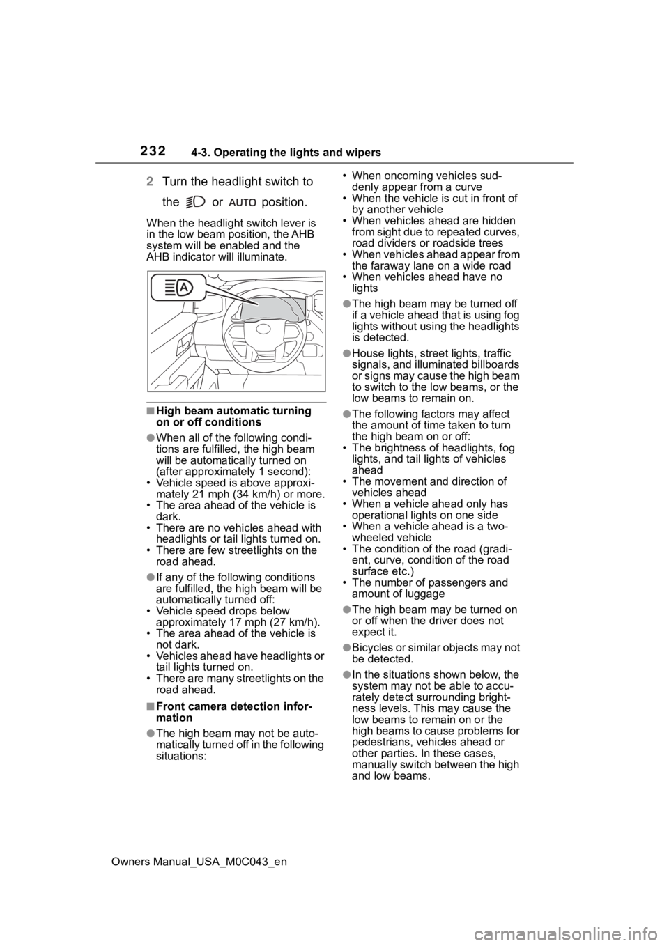
2Turn the headlight switch to
the or position.
When the headlight switch lever is
in the low beam position, the AHB
system will be enabled and the
AHB indicator will illuminate.
■High beam automatic turning
on or off conditions
●When all of the following condi-
tions are fulfille d, the high beam
will be automatica lly turned on
(after approximately 1 second):
• Vehicle speed is above approxi- mately 21 mph (34 km/h) or more.
• The area ahead of the vehicle is
dark.
• There are no vehicles ahead with headlights or tail lights turned on.
• There are few streetlights on the road ahead.
●If any of the following conditions
are fulfilled, the h igh beam will be
automatically turned off:
• Vehicle speed drops below approximately 17 mph (27 km/h).
• The area ahead of the vehicle is
not dark.
• Vehicles ahead have headlights or tail lights turned on.
• There are many streetlights on the road ahead.
■Front camera detection infor-
mation
●The high beam may not be auto-
matically turned off in the following
situations: • When oncoming vehicles sud-
denly appear from a curve
• When the vehicle is cut in front of
by another vehicle
• When vehicles ahead are hidden from sight due to repeated curves,
road dividers or roadside trees
• When vehicles ahead appear from the faraway lane on a wide road
• When vehicles ahead have no lights
●The high beam ma y be turned off
if a vehicle ahead that is using fog
lights without using the headlights
is detected.
●House lights, street lights, traffic
signals, and illuminated billboards
or signs may cause the high beam
to switch to the low beams, or the
low beams to remain on.
●The following fact ors may affect
the amount of time taken to turn
the high beam on or off:
• The brightness of headlights, fog
lights, and tail lig hts of vehicles
ahead
• The movement and direction of
vehicles ahead
• When a vehicle ahead only has
operational lights on one side
• When a vehicle ahead is a two- wheeled vehicle
• The condition of the road (gradi-
ent, curve, condition of the road
surface etc.)
• The number of passengers and
amount of luggage
●The high beam ma y be turned on
or off when the driver does not
expect it.
●Bicycles or similar objects may not
be detected.
●In the situations shown below, the
system may not be able to accu-
rately detect surrounding bright-
ness levels. This may cause the
low beams to remain on or the
high beams to cause problems for
pedestrians, vehicles ahead or
other parties. In these cases,
manually switch between the high
and low beams.
Page 252 of 628
2524-5. Using the driving support systems
Owners Manual_USA_M0C043_en
WARNING
●Emergency steering assist may
not operate or may be cancel in
the following cases as the sys-
tem may determine the driver is
taking actions.
• If the accelerato r pedal is being
depressed strongly, the steering
wheel is being operated sharply,
the brake pedal is being
depressed or the turn signal
lever is being ope rated. In this
case, the system may deter-
mine that the driver is taking
evasive action and the emer-
gency steering assist may not
operate.
• The emergency steering assist will be disabled automatically
when the system judges that a
trailer is connected.
• In some situations, while the emergency steering assist is
operating, operation of the func-
tion may be canceled if the
accelerator peda l is depressed
strongly, the st eering wheel is
operated sharply or the brake
pedal is being depressed and
the system determines that the
driver is taking evasive action.
• When the emergency steering assist is operating, if the steer-
ing wheel is held firmly or is
operated in the opposite direc-
tion to that which the system is
generating torque, the function
may be canceled.
■When to disable the pre-colli-
sion system
In the following situations, disable
the system, as it may not operate
properly, possibly leading to an
accident resulting in death or seri-
ous injury:
●When the vehicle is being towed
●When your vehicles is towing a
trailer or another vehicle, except
when the followin g conditions
are all met
• When the other vehicle is a trailer properly attached and
connected to Toyota’s official
TBC ECU. ( P.198)
• When the vehicle is not being driven on a slippery surface
such as an icy road or a very
wet road.
●When transporting the vehicle
via truck, boat, train or similar
means of transportation
●When the vehicle is raised on a
lift with the hybrid system on
and the tires are allowed to
rotate freely
●When inspecting the vehicle
using a drum tester such as a
chassis dynamometer or speed-
ometer tester, or when using an
on vehicle wheel balancer
●When a strong impact is applied
to the front bumper or front
grille, due to an accident or
other reasons
●If the vehicle cannot be driven in
a stable manner, such as when
the vehicle has been in an acci-
dent or is malfunctioning
●When the vehicle is driven in a
sporty manner or off-road
●When the tires are not properly
inflated
●When the tires are very worn
●When tires of a size other than
specified are installed
●When tire chains are installed
●When a compact spare tire or
an emergency tire puncture
repair kit is used
Page 255 of 628
2554-5. Using the driving support systems
Owners Manual_USA_M0C043_en
4
Driving
• The steering wheel is tur ned sharply or abruptly.
●Emergency steering assist
When the turn signal lights are flashing, emergency steering as sist will not
operate in case of an emergency.
The emergency steeri ng assist will be disabl ed automatically when the sys-
tem judges that a trailer is connected.
If any of the following occur wh ile the emergency steering assi st function is
operating, it will be canceled:
• The accelerator pedal is depressed strongly.
• The steering wheel is tur ned sharply or abruptly.
• The brake pedal is depressed.
●Intersection right/left turn assistance (pre-collision warning)
When the turn signal lights are not flashing, support for turning left or right at
an intersection which targets on coming vehicles does not work.
When the system judges that a trailer is detected, intersection support is dis-
abled for vehicles and pedestrians.
●Intersection right/left turn assistance (pre-collision braking)
When the turn signal lights are not flashing, support for turning left or right at
an intersection which targets on coming vehicles does not work.
When the system judges that a trailer is detected, intersection support is dis-
abled for vehicles and pedestrians.
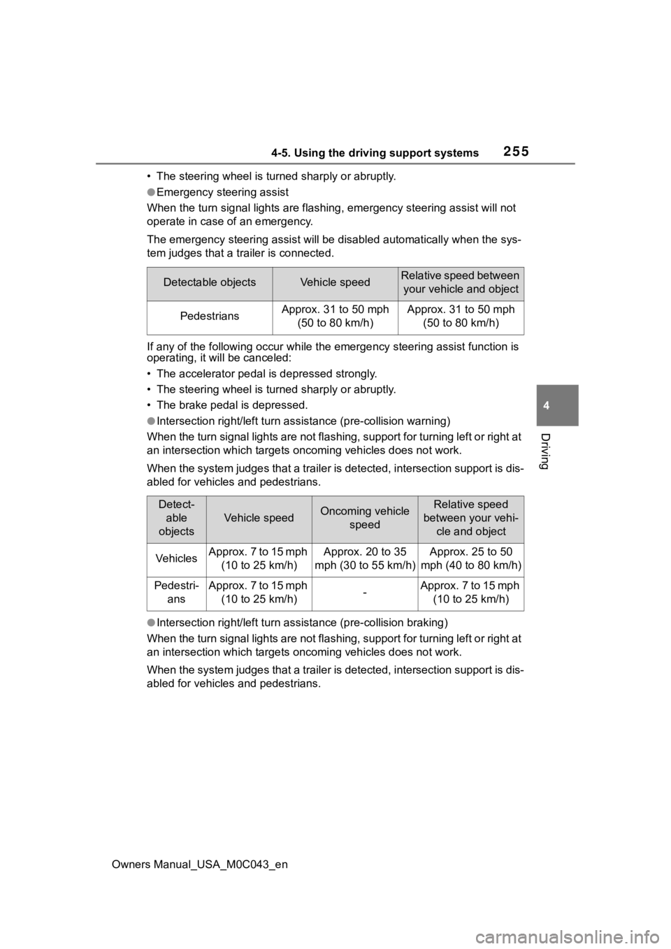
Detectable objectsVehicle speedRelative speed between your vehicle and object
PedestriansApprox. 31 to 50 mph (50 to 80 km/h)Approx. 31 to 50 mph (50 to 80 km/h)
Detect-able
objects
Vehicle speedOncoming vehicle speedRelative speed
between your vehi- cle and object
VehiclesApprox. 7 to 15 mph (10 to 25 km/h)Approx. 20 to 35
mph (30 to 55 km/h)Approx. 25 to 50
mph (40 to 80 km/h)
Pedestri- ansApprox. 7 to 15 mph (10 to 25 km/h)-Approx. 7 to 15 mph (10 to 25 km/h)
Page 265 of 628
2654-5. Using the driving support systems
Owners Manual_USA_M0C043_en
4
Driving
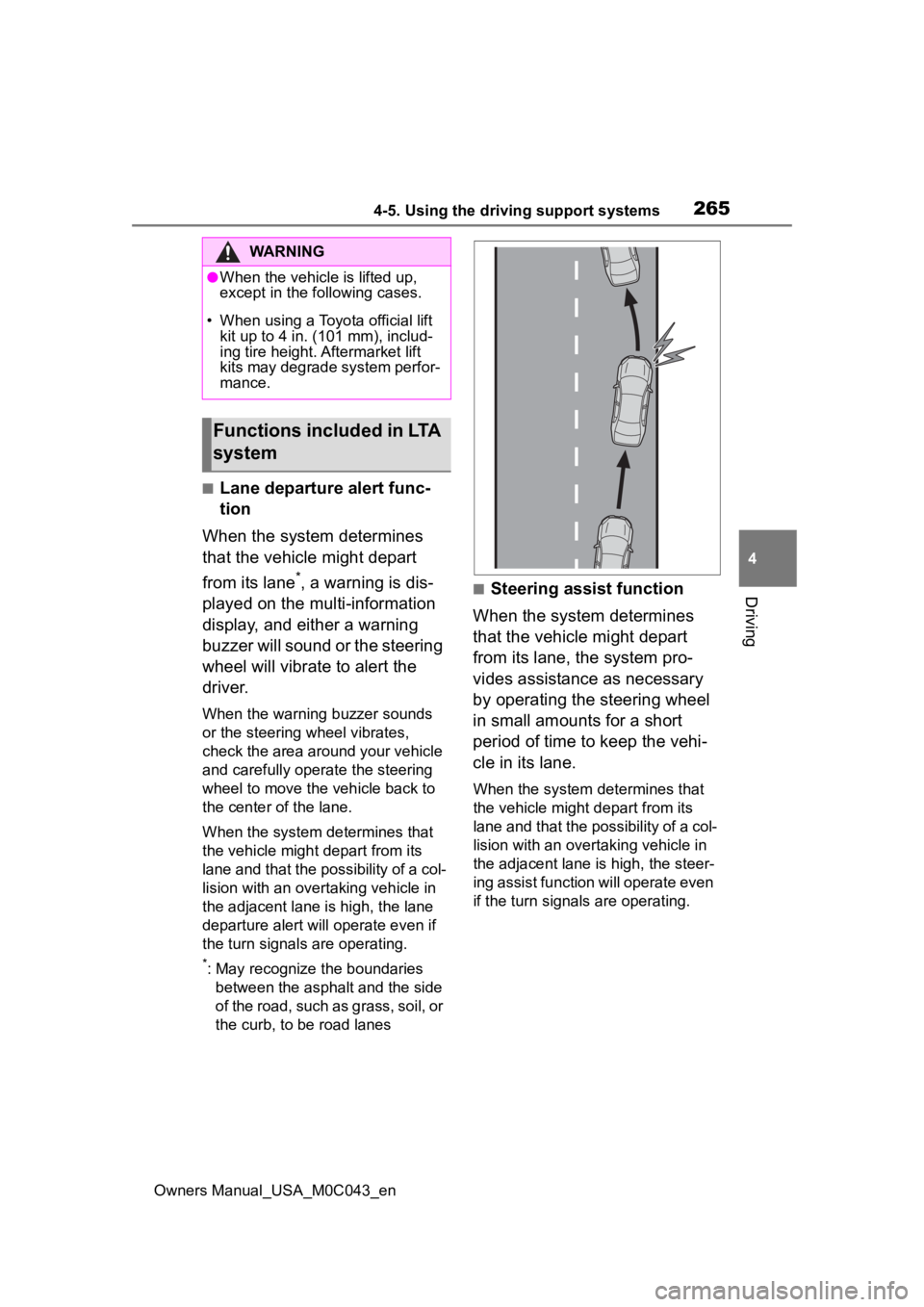
■Lane departure alert func-
tion
When the system determines
that the vehicle might depart
from its lane
*, a warning is dis-
played on the multi-information
display, and either a warning
buzzer will sound or the steering
wheel will vibrate to alert the
driver.
When the warning buzzer sounds
or the steering wheel vibrates,
check the area around your vehicle
and carefully operate the steering
wheel to move the vehicle back to
the center of the lane.
When the system determines that
the vehicle might depart from its
lane and that the possibility of a col-
lision with an overtaking vehicle in
the adjacent lane is high, the lane
departure alert will operate even if
the turn signals are operating.
*: May recognize the boundaries between the asphalt and the side
of the road, such as grass, soil, or
the curb, to be road lanes
■Steering assist function
When the system determines
that the vehicle might depart
from its lane, the system pro-
vides assistance as necessary
by operating the steering wheel
in small amounts for a short
period of time to keep the vehi-
cle in its lane.
When the system determines that
the vehicle might depart from its
lane and that the possibility of a col-
lision with an overta king vehicle in
the adjacent lane is high, the steer-
ing assist function will operate even
if the turn signals are operating.
WARNING
●When the vehicle is lifted up,
except in the following cases.
• When using a Toyota official lift kit up to 4 in. (101 mm), includ-
ing tire height. Aftermarket lift
kits may degrade system perfor-
mance.
Functions included in LTA
system
Page 269 of 628
2694-5. Using the driving support systems
Owners Manual_USA_M0C043_en
4
Driving
■Operation conditions of each
function
●Lane departure alert function
This function oper ates when all of
the following cond itions are met.
• LTA is turned on.
• Vehicle speed is approximately 32
mph (50 km/h) or more.
*1
• System recognizes white (yellow)
lane lines*2. (When a white [yel-
low] line*2 is recognized on only
one side, the system will operate
only for the reco gnized side.)
• Width of traffic lane is approxi- mately 9.8 ft. ( 3 m) or more.
• Turn signal lever is not operated.
(Except when another vehicle is in
the lane on the side where the
turn signal was operated)
• Vehicle is not being driven around a sharp curve.
• No system malfunctions are detected. ( P.271)
*1: The function opera tes even if the
vehicle speed is less than
approximately 32 mph (50 km/h)
when the lane centering function
is operating.
*2: May recognize the boundaries between the asphalt and the side
o f t he r oa d, su ch as gr as s, s oil, or
the curb, to be road lanes
●Steering assist function
This function oper ates when all of
the following conditions are met in
addition to the operation conditions
for the lane departure alert function.
• Vehicle is not accelerated or decelerated by a fixed amount or
more.
• Steering wheel is not operated with a steering force level suitable
for changing lanes.
• ABS, VSC, TRAC and PCS are not operating.
• TRAC or VSC is not turned off.
• Hands off steering wheel warning is not displayed. (
P.270)
●Vehicle sway warning function
This function operates when all of
the following conditions are met.
• Setting for “Sway Warning” in
of the multi-information display is
set to “ON”. ( P.578)
• Vehicle speed is approximately 32
mph (50 km/h) or more.
• Width of traffic lane is approxi- mately 9.8 ft. (3 m) or more.
• No system malfunctions are detected. ( P.271)
●Lane centering function
This function operates when all of
the following conditions are met.
• LTA is turned on.
• Setting for “Lane Center” in of
the multi-informatio n display is set
to “ON”. ( P.578)
• This function recognizes white
(yellow) lane lines or the position
of a preceding v ehicle (except
when the preceding vehicle is
small, such as a motorcycle).
• The dynamic radar cruise control with full-speed ran ge is operating
in vehicle-to-vehicle distance con-
trol mode.
• Width of traffic lane is approxi- mately 10 to 13 ft. (3 to 4 m).
• Turn signal lever is not operated.
• Vehicle is not being driven around a sharp curve.
• No system malfunctions are detected. ( P.271)
• Vehicle does not accelerate or
decelerate by a fixed amount or
more.
• Steering wheel is not operated
with a steering force level suitable
for changing lanes.
• ABS, VSC, TRAC and PCS are
not operating.
• TRAC or VSC is not turned off.
• Hands off steering wheel warning is not displayed. ( P.270)
• The vehicle is being driven in the center of a lane.
Page 279 of 628
2794-5. Using the driving support systems
Owners Manual_USA_M0C043_en
4
Driving
control continues to keep your vehicle stopped.
When the turn signal lever is ope rated and your vehicle moves to an over-
taking lane while driving at 50 mph (80 km/h) or more, the vehi cle will accel-
erate to help to overt ake a passing vehicle.
The system’s identification of what is an overtaking lane may be determined
solely based on the location of the steering wheel in the vehicle (left side
driver position versus right side driver position.) If the vehi cle is driven to a
region where the overtaking lane is on a different side from wh ere the vehi-
cle is normally driven, the vehicle may accelerate when the tur n signal lever
is operated in the opposite direction to the overtaking lane (e .g., if the driver
normally operates the vehicle in a region where the overtaking lane is to the
right but then drives to a region where the overtaking lane is to the left, the
vehicle may accelerate when the right turn signal is activated).
Example of acceleration
When there are no longer any preceding vehicles driving slower
than the set speed
The system accelerates until the set speed is reached. The system then
returns to constan t speed cruising.
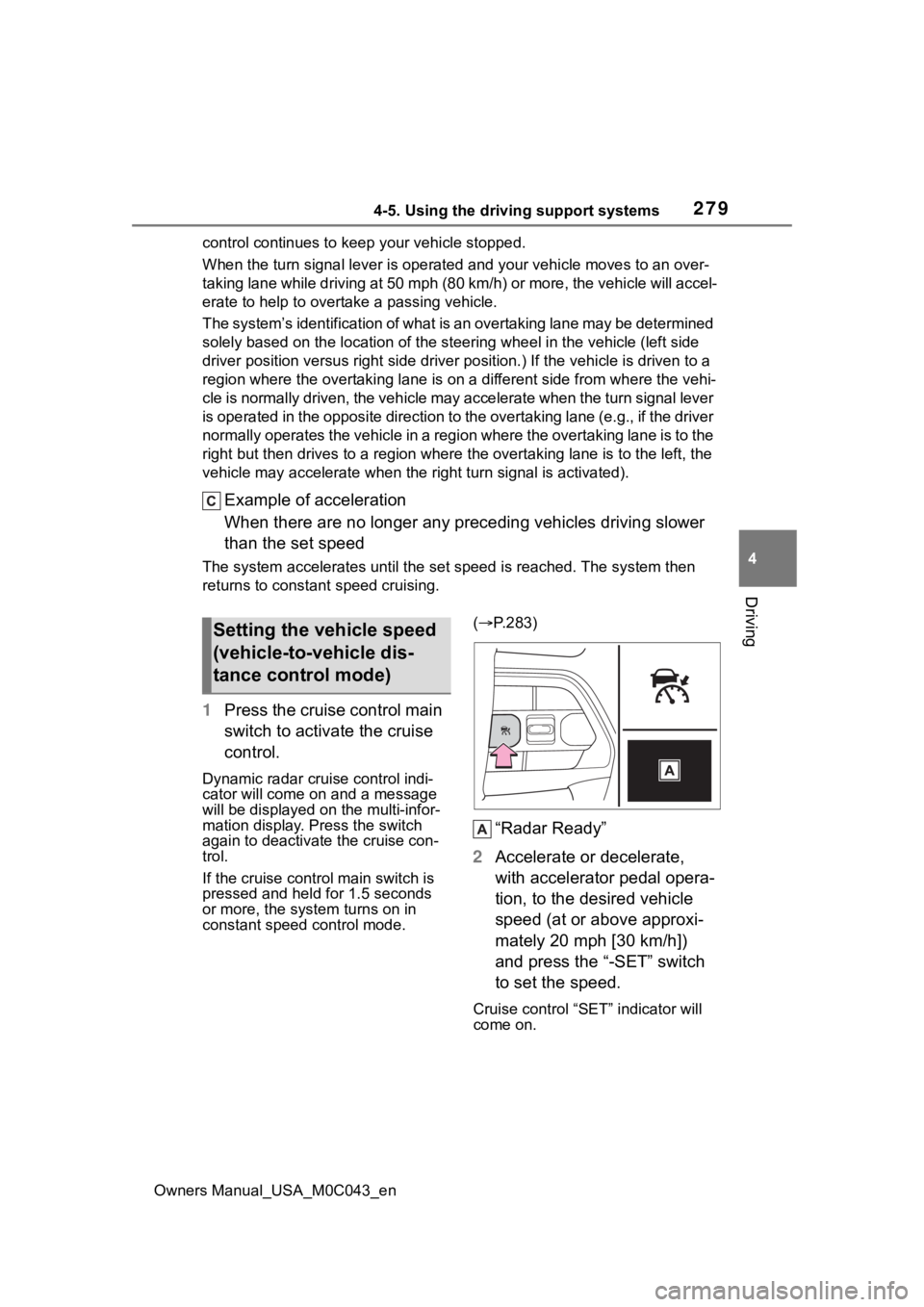
1Press the cruise control main
switch to activate the cruise
control.
Dynamic radar cruise control indi-
cator will come on and a message
will be displayed on the multi-infor-
mation display. Press the switch
again to deactivate the cruise con-
trol.
If the cruise cont rol main switch is
pressed and held for 1.5 seconds
or more, the syste m turns on in
constant speed control mode. (
P.283)
“Radar Ready”
2 Accelerate or decelerate,
with accelerator pedal opera-
tion, to the desired vehicle
speed (at or above approxi-
mately 20 mph [30 km/h])
and press the “-SET” switch
to set the speed.
Cruise control “SET” indicator will
come on.
Setting the vehicle speed
(vehicle-to-vehicle dis-
tance control mode)
Page 287 of 628
2874-5. Using the driving support systems
Owners Manual_USA_M0C043_en
4
Driving
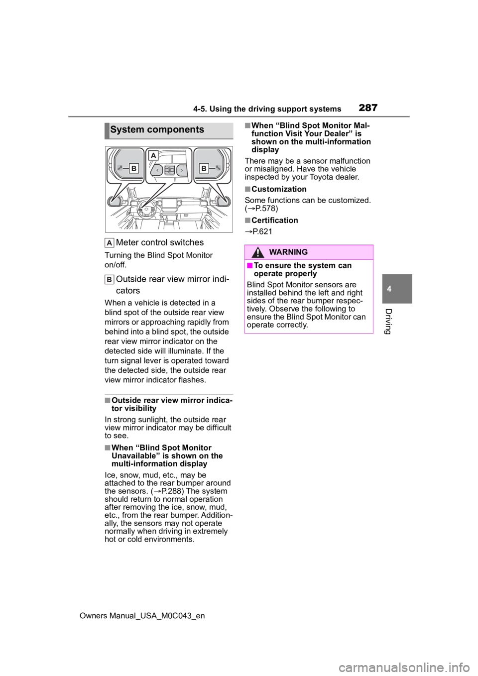
Meter control switches
Turning the Blind Spot Monitor
on/off.
Outside rear view mirror indi-
cators
When a vehicle is detected in a
blind spot of the outside rear view
mirrors or approaching rapidly from
behind into a blind spot, the outside
rear view mirror indicator on the
detected side will illuminate. If the
turn signal lever is operated toward
the detected side, the outside rear
view mirror indicator flashes.
■Outside rear view mirror indica-
tor visibility
In strong sunlight, the outside rear
view mirror indicato r may be difficult
to see.
■When “Blind Spot Monitor
Unavailable” is shown on the
multi-information display
Ice, snow, mud, etc., may be
attached to the rear bumper around
the sensors. ( P.288) The system
should return to normal operation
after removing the ice, snow, mud,
etc., from the rear bumper. Addition-
ally, the sensors may not operate
normally when driving in extremely
hot or cold environments.
■When “Blind Spot Monitor Mal-
function Visit Your Dealer” is
shown on the multi-information
display
There may be a sensor malfunction
or misaligned. Have the vehicle
inspected by your Toyota dealer.
■Customization
Some functions can be customized.
( P.578)
■Certification
P.621
System components
WARNING
■To ensure the system can
operate properly
Blind Spot Monitor sensors are
installed behind the left and right
sides of the rear bumper respec-
tively. Observe the following to
ensure the Blind Spot Monitor can
operate correctly.
Page 477 of 628
4776-3. Do-it-yourself maintenance
Owners Manual_USA_M0C043_en
6
Maintenance and care
■How to change the unit
1 Park the vehicle in a safe
place and turn the power
switch off.
Changing the unit cannot be per-
formed while the vehicle is moving.
2Turn the power switch to ON.
3 Press or of the meter
control switch to select .
4 Press or to select
“Vehicle Settings” and then
press and hold .
5 Press or to select
“TPWS” and then press .
6 Press or to select “Set
Unit” and then press .
7 Press or to select the
desired unit and then press
.
■Routine tire inflation pressure
checks
The tire pressure warning system
does not replace routine tire inflation
pressure checks. Make sure to
check tire inflation pressure as part
of your routine of daily vehicle
checks.
■Tire inflation pressure
●It may take a few minutes to dis-
play the tire inflation pressure
after the power switch is turned to
ON. It may also take a few min-
utes to display the tire inflation
pressure after inflation pressure
has been adjusted.
●Tire inflation pressure changes
with temperature. The displayed
values may also be different from
the values measured using a tire
pressure gauge.
■Situations in which the tire
pressure warning system may
not operate properly
●In the following cases, the tire
pressure warning system may not
operate properly.
• If non-genuine Toyota wheels are
used.
• A tire has been replaced with a
tire that is not an OE (Original
Equipment) tire.
• A tire has been replaced with a
tire that is not of the specified size.
• Tire chains, etc. , are equipped.
• An auxiliary-support ed run-flat tire
is equipped.
• If a window tint that affects the radio wave signals is installed.
• If there is a lot of snow or ice on
the vehicle, particularly around the
wheels or wheel housings.
• If the tire inflation pressure is
extremely higher than the speci-
fied level.
• If wheels without tire pressure
warning valves and transmitters
are used.
• If the ID code on the tire pressure
warning valves and transmitters is
not registered in the tire pressure
warning computer.
●Performance may be affected in
the following situations.
• Near a TV tower, electric power plant, gas station, radio station,
large display, airpo rt or other facil-
ity that generates strong radio
waves or electrical noise
• When carrying a portable radio,
cellular phone, cordless phone or
other wireless communication
device
If tire position info rmation is not cor-
rectly displayed due to the radio
wave conditions, the display may be
corrected by driving and changing
the radio wave c onditions may
Page 498 of 628
4986-3. Do-it-yourself maintenance
Owners Manual_USA_M0C043_en
Check the wattage of the light
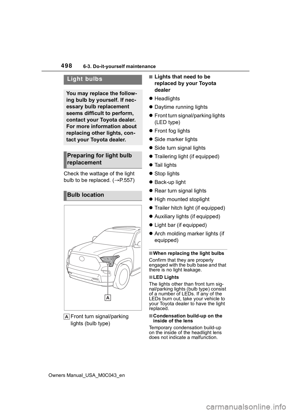
bulb to be replaced. ( P.557)
Front turn signal/parking
lights (bulb type)
■Lights that need to be
replaced by your Toyota
dealer
Headlights
Daytime running lights
Front turn signal/parking lights
(LED type)
Front fog lights
Side marker lights
Side turn signal lights
Trailering light (if equipped)
Tail lights
Stop lights
Back-up light
Rear turn signal lights
High mounted stoplight
Trailer hitch light (if equipped)
Auxiliary lights (if equipped)
Light bar (if equipped)
Arch molding marker lights (if
equipped)
■When replacing the light bulbs
Confirm that they are properly
engaged with the bulb base and that
there is no light leakage.
■LED Lights
The lights other than front turn sig-
nal/parking lights (b ulb type) consist
of a number of LEDs. If any of the
LEDs burn out, take your vehicle to
your Toyota dealer to have the light
replaced.
■Condensation build-up on the
inside of the lens
Temporary condensation build-up
on the inside of t he headlight lens
does not indicate a malfunction.
Light bulbs
You may replace the follow-
ing bulb by yourself. If nec-
essary bulb replacement
seems difficult to perform,
contact your Toyota dealer.
For more information about
replacing other lights, con-
tact your Toyota dealer.
Preparing for light bulb
replacement
Bulb location