engine TOYOTA SEQUOIA HYBRID 2023 Owners Manual
[x] Cancel search | Manufacturer: TOYOTA, Model Year: 2023, Model line: SEQUOIA HYBRID, Model: TOYOTA SEQUOIA HYBRID 2023Pages: 628, PDF Size: 14.27 MB
Page 4 of 628
4TABLE OF CONTENTS
Owners Manual_USA_M0C043_en
Downhill assist control sys-tem .............................. 380
Driving assist systems .. 382
Trailer brake controller .. 388
Trailer Backup Guide .... 391
4-6. Driving tips Hybrid Electric Vehicle driving tips............................... 396
Off-road precautions ..... 398
Winter driving tips ......... 401
5-1. Using the air conditioning
system and defogger
Automatic air conditioning system ......................... 406
Rear automatic air condition- ing system ................... 413
Heated steering wheel/seat heaters/seat ventilators 415
5-2. Using the interior lights Interior lights list ............ 418
5-3. Using the storage features List of storage features . 421
Luggage compartment fea- tures ............................ 425
5-4. Using the other interior fea- tures
Other interior features ... 428
Garage door opener...... 4416-1. Maintenance and care
Cleaning and protecting the vehicle exterior ............ 450
Cleaning and protecting the vehicle interior ............. 453
6-2. Maintenance Maintenance requirements.................................... 456
General maintenance .... 457
Emission inspection and maintenance (I/M) programs.................................... 460
6-3. Do-it-yourself maintenance Do-it-yourself service precau-tions ............................. 462
Hood .............................. 464
Engine compartment ..... 465
12-volt battery................ 471
Tires .............................. 474
Tire inflation pressure .... 484
Wheels .......................... 486
Air conditioning filter ...... 487
Cleaning the hybrid battery (traction battery) air intake
vent and filter ............... 489
Electronic key battery .... 493
Checking and replacing fuses .................................... 495
Light bulbs ..................... 498
5Interior features
6Maintenance and care
Page 7 of 628
7
Owners Manual_USA_M0C043_en
properly or the danger that it
may work in situations where it
should not be working.
The installation of a mobile two-
way radio system in your vehicle
could affect electronic systems
such as:
Multiport fuel injection sys-
tem/sequential multiport fuel
injection system
Toyota Safety Sense 2.5
Anti-lock brake system
Vehicle dynamics integrated
management
SRS airbag system
Seat belt pretensioner system
Be sure to check with your Toy-
ota dealer for precautionary
measures or special instructions
regarding installation of a mobile
two-way radio system.
The vehicle is equipped with
sophisticated computers that will
record certain data, such as:
• Engine speed / Electric motor speed (traction motor speed)
• Accelerator status
• Brake status
• Vehicle speed
• Operation status of the driving assist systems • Images from the cameras
Your vehicle is equipped with cam-
eras. Contact your Toyota dealer for
the location of re
cording cameras.
The recorded data varies
according to the vehicle grade
level and options with which it is
equipped.
These computers do not record
conversations or sounds, and
only record images outside of
the vehicle in certain situations.
Data Transmission
Your vehicle may transmit the data
recorded in these computers to
Toyota without notification to you.
Data usage
Toyota may use the data recorded
in this computer to diagnose mal-
functions, conduct research and
development, and improve quality.
Toyota will not disclose the
recorded data to a third party
except:
• With the consen t of the vehicle
owner or with the consent of the
lessee if the vehicle is leased
• In response to an official request by the police, a court of law or a
government agency
• For use by Toyota in a lawsuit
• For research purposes where the data is not tied to a specific vehi-
cle or vehicle owner
Recorded image information
can be erased by your Toyota
dealer.
The image recording function can
be disabled. However, if the func-
Installation of a mobile
two-way radio system
Vehicle data recording
Page 15 of 628
15Pictorial index
Owners Manual_USA_M0C043_en
Defogging the mirrors .......................................... ................ P.408
Windshield wipers.............................................. ................ P.235
Rear window wiper .............................................. .............. P.239
Precautions for winter seas on.............................................. P.401
To prevent freezing (windshield wiper de-icer)
*.................... P.411
Precautions for car wash (vehicles with rain-sensing windshield wip-
ers)
*...................................................................................... P.451
Fuel filler door ............................................... ..................... P.241
Refueling method ............................................... .................. P.241
Fuel type/fuel tan k capacity ................................... .............. P.550
Tires.......................................................... ........................... P.474
Tire size/inflation pressure ................................... ................ P.555
Winter tires/tire chains ....................................... .................. P.401
Checking/rotation/tire pressur e warning system ..................P.474
Coping with flat tires......................................... .................... P.523
Hood ........................................................... ......................... P.464
Opening ............................................................................... P.464
Engine oil ..................................................... ........................ P.551
Coping with overheating ...................................................... P.543
Headlights..................................................... ...................... P.228
Parking lights ................................................. .................... P.228
Turn signal lights ............................................. .................. P.221
Daytime running lights .. .................................................... P.228
Head lights/daytime running lights ............................. ..... P.228
Turn signal lights ............................................. .................. P.221
Parking lights ................................................. .................... P.228
Side marker lights
*............................................................. P. 228
Light bulbs of the exterior lights for driving
(Replacing method: P.498, Watts: P.557)
Page 39 of 628
391-1. For safe use
Owners Manual_USA_M0C043_en
1
For safety and security
Driver’s seat bel t buckle switch
Driver’s seat position sensor
Front passenger’s seat belt buckle switch
Airbag sensor assembly
Your vehicle is equipped with ADVANCED AIRBAGS designed
based on the US motor vehicle safety standards (FMVSS208). The
airbag sensor assembly (ECU) cont rols airbag deployment based on
information obtained from the sensors etc. shown in the system
components diagram above. This in formation includes crash sever-
ity and occupant information. As the airbags deploy, a chemical
reaction in the inflators quickly fills the airbags with non-toxic gas to
help restrain the motion of the occupants.
■If the SRS airbags deploy
(inflate)
●Slight abrasions, burns, bruising,
etc., may be sustained from SRS
airbags, due to the extremely high
speed deployment (inflation) by
hot gases.
●A loud noise and white powder will
be emitted.
●Parts of the airbag module (steer-
ing wheel hub, airbag cover and
inflator) as well as the front seats,
parts of the front and rear pillars,
and roof side rails, may be hot for
several minutes. T he airbag itself
may also be hot.
●The windshield may crack.
●The hybrid system will be stopped
and fuel supply to the engine will
be stopped. ( P. 8 1 )
●All of the doors will be unlocked.
( P.116)
●The brakes and st op lights will be
controlled automatically. ( P.383)
●The interior lights will turn on auto-
matically. ( P.420)
●The emergency flashers will turn
on automatically. ( P.502)
●For Safety Connect subscribers, if
any of the following situations occur, the system is designed to
send an emergency call to the
response center, notifying them of
the vehicle’s location (without
needing to push the “SOS” button)
and an agent will attempt to speak
with the occupants to ascertain
the level of emergency and assis-
tance required. If the occupants
are unable to communicate, the
agent automatically treats the call
as an emergency and helps to dis-
patch the necessary emergency
services. (
P. 7 0 )
• An SRS airbag is deployed.
• A seat belt pretensioner is acti- vated.
• The vehicle is involved in a severe rear-end collision.
■SRS airbag deployment condi-
tions (SRS front airbags)
●The SRS front airbags will deploy
in the event of an impact that
exceeds the set threshold level
(the level of forc e corresponding
to an approximately 12 - 18 mph
[20 - 30 km/h] frontal collision with
a fixed wall that does not move or
deform).
However, this threshold velocity will
be considerably higher in the follow-
ing situations:
• If the vehicle strikes an object,
Page 73 of 628
731-3. Emergency assistance
Owners Manual_USA_M0C043_en
1
For safety and security
necessary assistance required.
If you accidentally press the “SOS”
button, tell the response-center
agent that you are not experiencing
an emergency.
■Enhanced Roadside Assis-
tance
Enhanced Roadside Assistance
adds GPS data to the already
included warranty-based Toyota
roadside service.
Subscribers can press the
“SOS” button to reach a Safety
Connect response-center agent,
who can help with a wide range
of needs, such as: towing, flat
tire, fuel delivery, etc. For a
description of the Roadside
Assistance services and their
limitations, please see the
Safety Connect Terms and Con-
ditions, which are available at
Toyota.com.
Important! Read this informa-
tion about exposure to radio fre-
quency signals before using
Safety Connect;
The Safety Connect system
installed in your vehicle is a low-
power radio transmitter and
receiver. It receives and also
sends out radio frequency (RF)
signals.
In August 1996, the Federal
Communications Commission (FCC) adopted RF exposure
guidelines with safety levels for
mobile wireless phones. Those
guidelines are consistent with
the safety standards previously
set by the following U.S. and
international standards bodies.
ANSI (American National
Standards Institute) C95.1
[1992]
NCRP (National Council on
Radiation Protection and
Measurement) Report 86
[1986]
ICNIRP (International Com-
mission on Non-Ionizing Radi-
ation Protection) [1996]
Those standards were based on
comprehensive and periodic
evaluations of the relevant sci-
entific literature. Over 120 scien-
tists, engineers, and physicians
from universities, and govern-
ment health agencies and
industries reviewed the avail-
able body of research to
develop the ANSI Standard
(C95.1).
The design of Safety Connect
complies with the FCC guide-
lines in addition to those stan-
dards.
Safety information for
Safety Connect
Page 75 of 628

751-4. Hybrid system
Owners Manual_USA_M0C043_en
1
For safety and security
1-4.Hybrid system
■System components
The illustration is an example fo r explanation and may differ from the actual
item.
Gasoline engine
Electric motor (traction motor)
■When stopped/during start
off
The gasoline engine stops
* when the vehicle is stopped.
During start off, the electric
motor (traction motor) drives the
Hybrid system features
Your vehicle is a Hybrid Electric Vehicle. It has characteristi
cs
different from conventional vehicles. Be sure you are closely
familiar with the characteristics of your vehicle, and operate it
with care.
The hybrid system combines the use of a gasoline engine and
an electric motor (traction motor) according to driving condi-
tions, improving fuel efficiency and reducing exhaust emis-
sions.
System components
Page 76 of 628
761-4. Hybrid system
Owners Manual_USA_M0C043_en
vehicle. At slow speeds or when
traveling down a gentle slope,
the engine is stopped
* and the
electric motor (traction motor) is
used.
*: When the hybrid battery (traction battery) requires charging or the
engine is warming up, etc., the
gasoline engine will not automati-
cally stop. ( P. 7 6 )
■During normal driving
The gasoline engine is predomi-
nantly used. The electric motor
(traction motor) charges the
hybrid battery (traction battery)
as necessary.
■When accelerating sharply
When the accelerator pedal is
depressed heavily, the power of
the hybrid battery (traction bat-
tery) is added to that of the gas-
oline engine via the electric
motor (traction motor).
■When braking (regenera-
tive braking)
The wheels operate the electric
motor (traction motor) as a
power generator, and the hybrid
battery (traction battery) is
charged.
■Regenerative braking
●In the following si tuations, kinetic
energy is converted to electric
energy and deceleration force can
be obtained in conjunction with
the recharging of the hybrid bat-
tery (traction battery).
• The accelerator pedal is released while driving with the shift lever in D or S.
• The brake pedal is depressed while driving with t he shift lever in
D or S.
■Conditions in which the gaso-
line engine may not stop
The gasoline engine starts and
stops automatically. However, it may
not stop automatic ally in the follow-
ing conditions:
●During gasoline engine warm-up
●During hybrid battery (traction bat-
tery) charging
●When the temperature of the
hybrid battery (traction battery) is
high or low
●When the heater is switched on
●When the “TOW HA UL” switch is
on
●When the “MTS” switch is on
●When the front-wheel drive control
switch is in “4H” or “4L”
●When the hood is opened during
“READY” indicator is illuminated
●When the shift lever is shifted to S
Depending on the circumstances,
the gasoline engine may also not
stop automatically in other situa-
tions.
■Charging the hybrid battery
(traction battery)
As the gasoline engine charges the
hybrid battery (trac tion battery), the
battery does not need to be charged
from an outside source. However, if
the vehicle is left parked for a long
time the hybrid battery (traction bat-
tery) will slowly dis charge. For this
reason, be sure to drive the vehicle
at least once every few months for
at least 30 minutes or 10 miles (16
km). If the hybrid battery (traction
battery) becomes fully discharged
and you are unabl e to start the
hybrid system, contact your Toyota
dealer.
Page 77 of 628
771-4. Hybrid system
Owners Manual_USA_M0C043_en
1
For safety and security
■Charging the 1 2-volt battery
P. 5 4 0
■After the 12-volt battery has dis-
charged or when the terminal
has been removed and installed
during exchange, etc.
The gasoline engine may not stop
even if the vehicle is being driven by
the hybrid battery (traction battery).
If this continues for a few days, con-
tact your Toyota dealer.
■Sounds and vibrations specific
to a Hybrid Electric Vehicle
There may be no engine sound or
vibration even though the vehicle is
able to move with the “READY” indi-
cator is illuminated. For safety, apply
the parking brake and make sure to
shift the shift lever to P when
parked.
The following sounds or vibrations
may occur when the hybrid system
is operating and are not a malfunc-
tion:
●Motor sounds may be heard from
the engine compartment.
●Sounds may be heard from the
hybrid battery (traction battery)
under the rear seats when the
hybrid system starts or stops.
●Relay operating sounds such as a
snap or soft clank will be emitted
from the hybrid battery (traction
battery), under the rear seats,
when the hybrid system is started
or stopped.
●Sounds may be heard from the
transmission when the gasoline
engine starts or stops, when driv-
ing at low speeds, or during idling.
●Engine sounds may be heard
when accelerating sharply.
●Sounds may be heard due to
regenerative braking when the
brake pedal is dep ressed or as
the accelerator pedal is released.
●Vibration may be felt when the
gasoline engine starts or stops.
●Cooling fan sounds may be heard
from the air intake vents on the
both sides of th e behind the sec-
ond seat.
■Maintenance, repair, recycling,
and disposal
Contact your Toyota dealer regard-
ing maintenance, repair, recycling
and disposal. Do n ot dispose of the
vehicle yourself.
When the gasoline engine is off
while driving, a sound is pro-
duced to warn pedestrians, peo-
ple riding bicycles or other
people and vehicles in the sur-
rounding area that the vehicle is
approaching. The pitch of the
sound adjusts according to vehi-
cle speed. When vehicle speed
is approximately 22 mph (35
km/h) or more, the warning sys-
tem turns off.
■Acoustic vehicle alerting sys-
tem
In the following cases, the acoustic
vehicle alerting system sound may
be difficult for pedestrians, people
riding bicycles or other people and
vehicles in the surrounding area to
hear:
●When there is a lot of noise in the
vicinity
●When it is raining or during strong
winds
Acoustic vehicle alerting
system
Page 89 of 628
892-1. Instrument cluster
Owners Manual_USA_M0C043_en
2
Vehicle status information and indicators
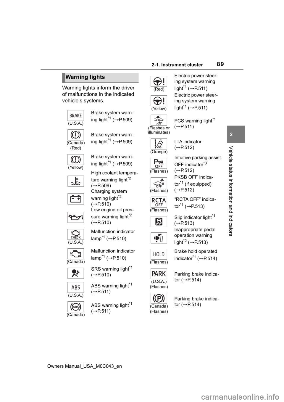
Warning lights inform the driver
of malfunctions in the indicated
vehicle’s systems.
Warning lights
(U.S.A.)
Brake system warn-
ing light
*1 ( P.509)
(Canada)
(Red)
Brake system warn-
ing light
*1 ( P.509)
(Yellow)
Brake system warn-
ing light
*1 ( P.509)
High coolant tempera-
ture warning light
*2
( P.509)
Charging system
warning light
*2
( P.510)
Low engine oil pres-
sure warning light
*2
( P.510)
(U.S.A.)
Malfunction indicator
lamp
*1 ( P.510)
(Canada)
Malfunction indicator
lamp
*1 ( P.510)
SRS warning light
*1
( P.510)
(U.S.A.)
ABS warning light*1
( P.511)
(Canada)
ABS warning light*1
( P.511)
(Red)
Electric power steer-
ing system warning
light
*1 ( P.511)
(Yellow)
Electric power steer-
ing system warning
light
*1 ( P.511)
(Flashes or
illuminates)
PCS warning light*1
( P.511)
(Orange)
LTA i n d i c a t o r
( P.512)
(Flashes)
Intuitive parking assist
OFF indicator
*3
( P.512)
(Flashes)
PKSB OFF indica-
tor
*1 (if equipped)
( P.512)
(Flashes)
“RCTA OFF” indica-
tor
*1 ( P.513)
Slip indicator light
*1
( P.513)
Inappropriate pedal
operation warning
light
*2 ( P.513)
(Flashes)
Brake hold operated
indicator
*1 ( P.514)
(U.S.A.)
(Flashes)
Parking brake indica-
tor ( P.514)
(Canada)
(Flashes)
Parking brake indica-
tor ( P.514)
Page 93 of 628
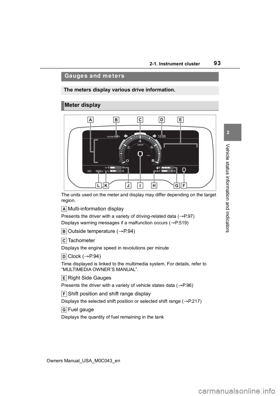
932-1. Instrument cluster
Owners Manual_USA_M0C043_en
2
Vehicle status information and indicators
The units used on the meter and display may differ depending on the target
region.
Multi-information display
Presents the driver with a variety of driving-related data ( P. 9 7 )
Displays warning messages if a malfunction occurs (P.519)
Outside temperature ( P. 9 4 )
Tachometer
Displays the engine speed in revolutions per minute
Clock ( P. 9 4 )
Time displayed is linked to the multimedia system. For details, refer to
“MULTIMEDIA OWNER’S MANUAL”.
Right Side Gauges
Presents the driver with a variety of vehicle states data ( P. 9 6 )
Shift position and shift range display
Displays the selected shift posit ion or selected shift range (P.217)
Fuel gauge
Displays the quantity of fu el remaining in the tank
Gauges and meters
The meters display various drive information.
Meter display