TOYOTA SIENNA 2007 Service Repair Manual
Manufacturer: TOYOTA, Model Year: 2007, Model line: SIENNA, Model: TOYOTA SIENNA 2007Pages: 3000, PDF Size: 52.26 MB
Page 2361 of 3000
BC–10BRAKE CONTROL – ANTI-LOCK BRAKE SYSTEM
BC
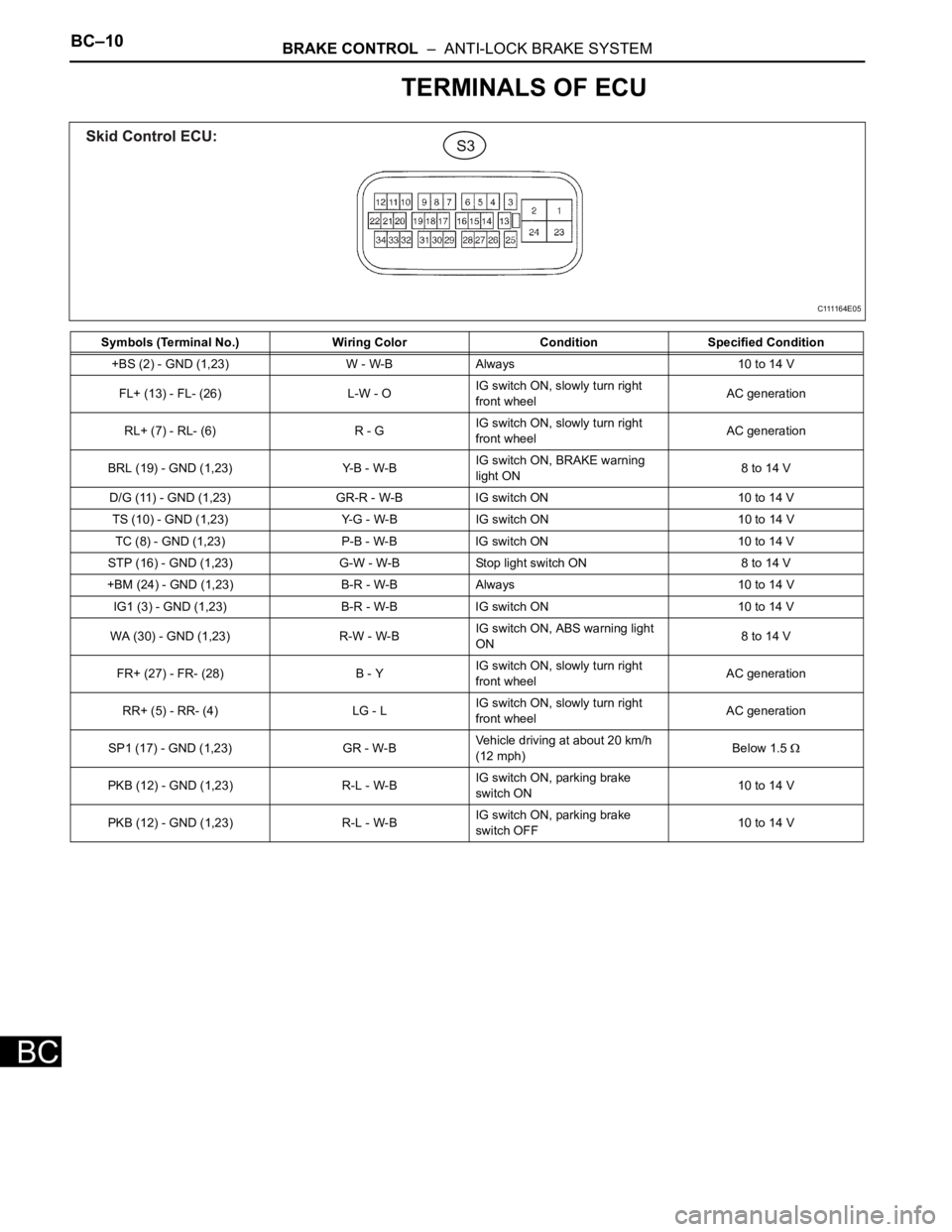
TERMINALS OF ECU
Symbols (Terminal No.) Wiring Color Condition Specified Condition
+BS (2) - GND (1,23) W - W-B Always 10 to 14 V
FL+ (13) - FL- (26) L-W - OIG switch ON, slowly turn right
front wheelAC generation
RL+ (7) - RL- (6) R - GIG switch ON, slowly turn right
front wheelAC generation
BRL (19) - GND (1,23) Y-B - W-BIG switch ON, BRAKE warning
light ON8 to 14 V
D/G (11) - GND (1,23) GR-R - W-B IG switch ON 10 to 14 V
TS (10) - GND (1,23) Y-G - W-B IG switch ON 10 to 14 V
TC (8) - GND (1,23) P-B - W-B IG switch ON 10 to 14 V
STP (16) - GND (1,23) G-W - W-B Stop light switch ON 8 to 14 V
+BM (24) - GND (1,23) B-R - W-B Always 10 to 14 V
IG1 (3) - GND (1,23) B-R - W-B IG switch ON 10 to 14 V
WA (30) - GND (1,23) R-W - W-BIG switch ON, ABS warning light
ON8 to 14 V
FR+ (27) - FR- (28) B - YIG switch ON, slowly turn right
front wheelAC generation
RR+ (5) - RR- (4) LG - LIG switch ON, slowly turn right
front wheelAC generation
SP1 (17) - GND (1,23) GR - W-BVehicle driving at about 20 km/h
(12 mph)Below 1.5
PKB (12) - GND (1,23) R-L - W-BIG switch ON, parking brake
switch ON10 to 14 V
PKB (12) - GND (1,23) R-L - W-BIG switch ON, parking brake
switch OFF10 to 14 V
C111164E05
Page 2362 of 3000
BRAKE CONTROL – ANTI-LOCK BRAKE SYSTEMBC–11
BC
DIAGNOSIS SYSTEM
1. DESCRIPTION
(a) Release the parking brake pedal.
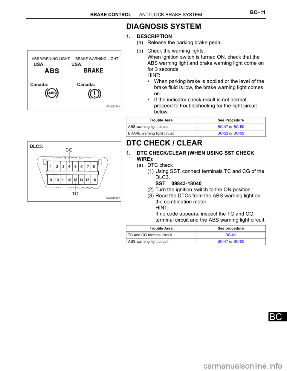
(b) Check the warning lights.
When ignition switch is turned ON, check that the
ABS warning light and brake warning light come on
for 3 seconds.
HINT:
• When parking brake is applied or the level of the
brake fluid is low, the brake warning light comes
on.
• If the indicator check result is not normal,
proceed to troubleshooting for the light circuit
below.
DTC CHECK / CLEAR
1. DTC CHECK/CLEAR (WHEN USING SST CHECK
WIRE):
(a) DTC check
(1) Using SST, connect terminals TC and CG of the
DLC3.
SST 09843-18040
(2) Turn the ignition switch to the ON position.
(3) Read the DTCs from the ABS warning light on
the combination meter.
HINT:
If no code appears, inspect the TC and CG
terminal circuit and the ABS warning light circuit.
F045097E01
Trouble Area See Procedure
ABS warning light circuitBC-47 or BC-50
BRAKE warning light circuitBC-52 or BC-59
G022986E01
Trouble Area See procedure
TC and CG terminal circuitBC-61
ABS warning light circuitBC-47 or BC-50
Page 2363 of 3000
BC–12BRAKE CONTROL – ANTI-LOCK BRAKE SYSTEM
BC
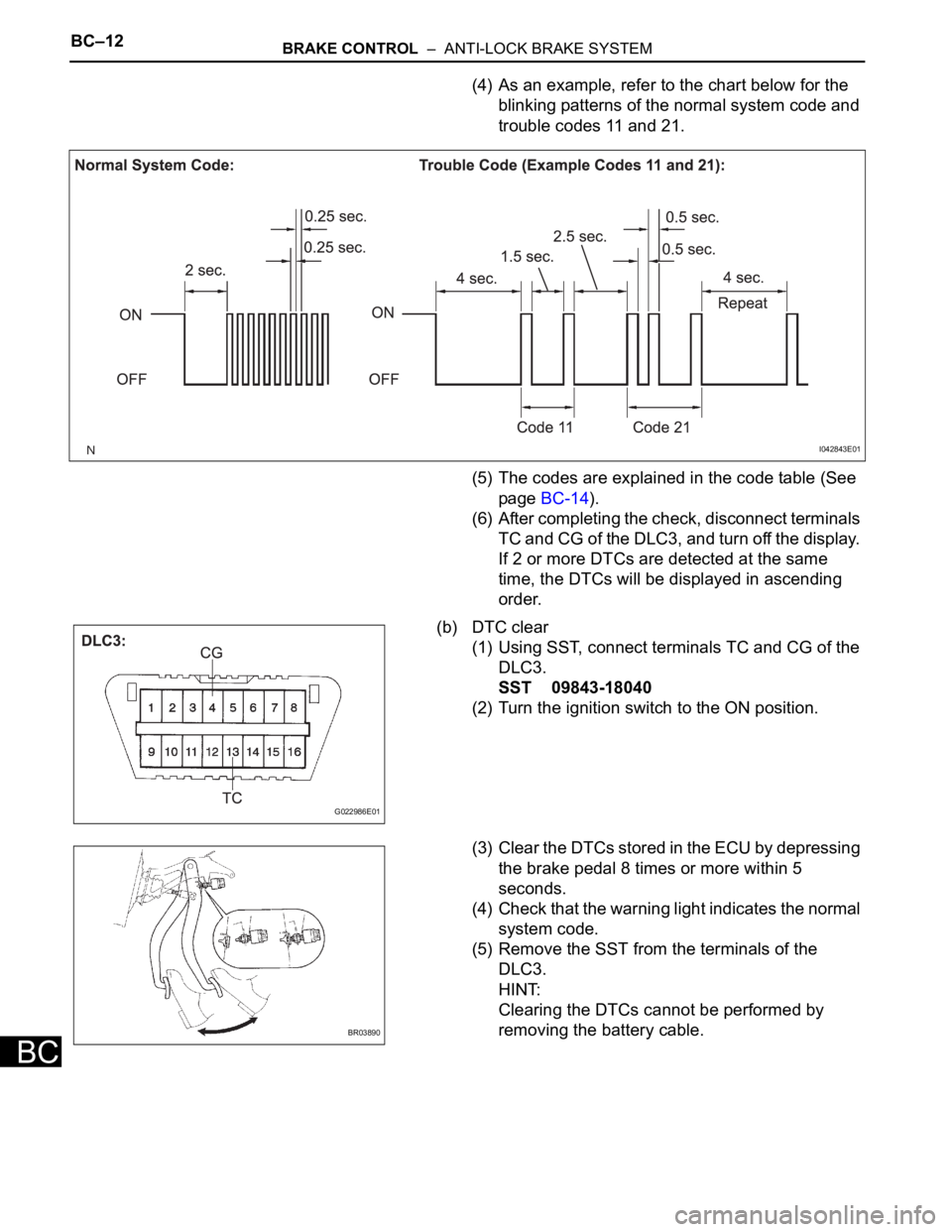
(4) As an example, refer to the chart below for the
blinking patterns of the normal system code and
trouble codes 11 and 21.
(5) The codes are explained in the code table (See
page BC-14).
(6) After completing the check, disconnect terminals
TC and CG of the DLC3, and turn off the display.
If 2 or more DTCs are detected at the same
time, the DTCs will be displayed in ascending
order.
(b) DTC clear
(1) Using SST, connect terminals TC and CG of the
DLC3.
SST 09843-18040
(2) Turn the ignition switch to the ON position.
(3) Clear the DTCs stored in the ECU by depressing
the brake pedal 8 times or more within 5
seconds.
(4) Check that the warning light indicates the normal
system code.
(5) Remove the SST from the terminals of the
DLC3.
HINT:
Clearing the DTCs cannot be performed by
removing the battery cable.
I042843E01
G022986E01
BR03890
Page 2364 of 3000
BRAKE CONTROL – ANTI-LOCK BRAKE SYSTEMBC–13
BC
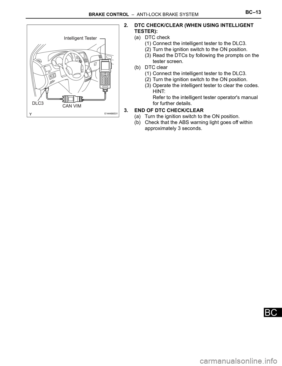
2. DTC CHECK/CLEAR (WHEN USING INTELLIGENT
TESTER):
(a) DTC check
(1) Connect the intelligent tester to the DLC3.
(2) Turn the ignition switch to the ON position.
(3) Read the DTCs by following the prompts on the
tester screen.
(b) DTC clear
(1) Connect the intelligent tester to the DLC3.
(2) Turn the ignition switch to the ON position.
(3) Operate the intelligent tester to clear the codes.
HINT:
Refer to the intelligent tester operator's manual
for further details.
3. END OF DTC CHECK/CLEAR
(a) Turn the ignition switch to the ON position.
(b) Check that the ABS warning light goes off within
approximately 3 seconds.
E144486E01
Page 2365 of 3000
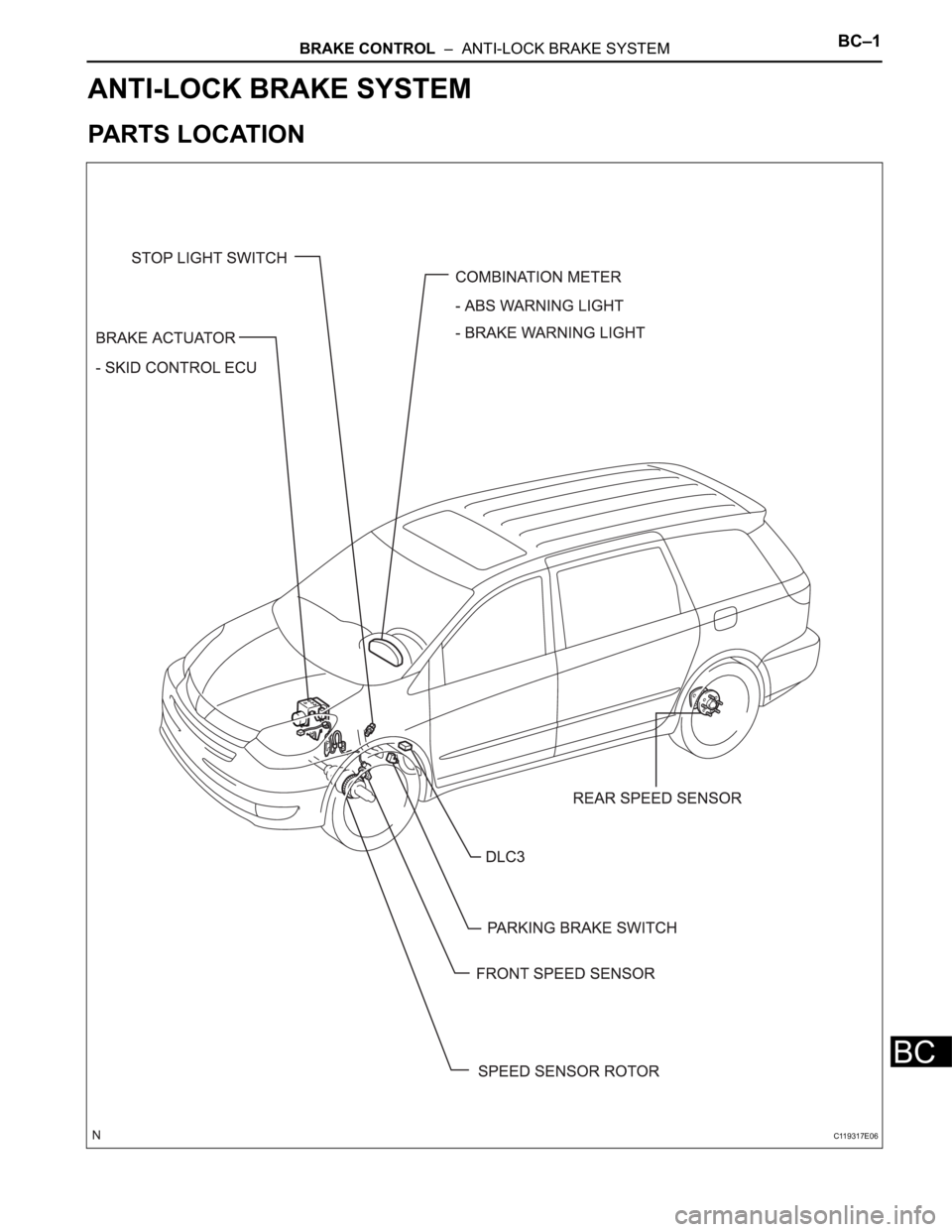
BRAKE CONTROL – ANTI-LOCK BRAKE SYSTEMBC–1
BC
BRAKE
BRAKE CONTROL
ANTI-LOCK BRAKE SYSTEM
PARTS LOCATION
C119317E06
Page 2366 of 3000
BC–2BRAKE CONTROL – ANTI-LOCK BRAKE SYSTEM
BC
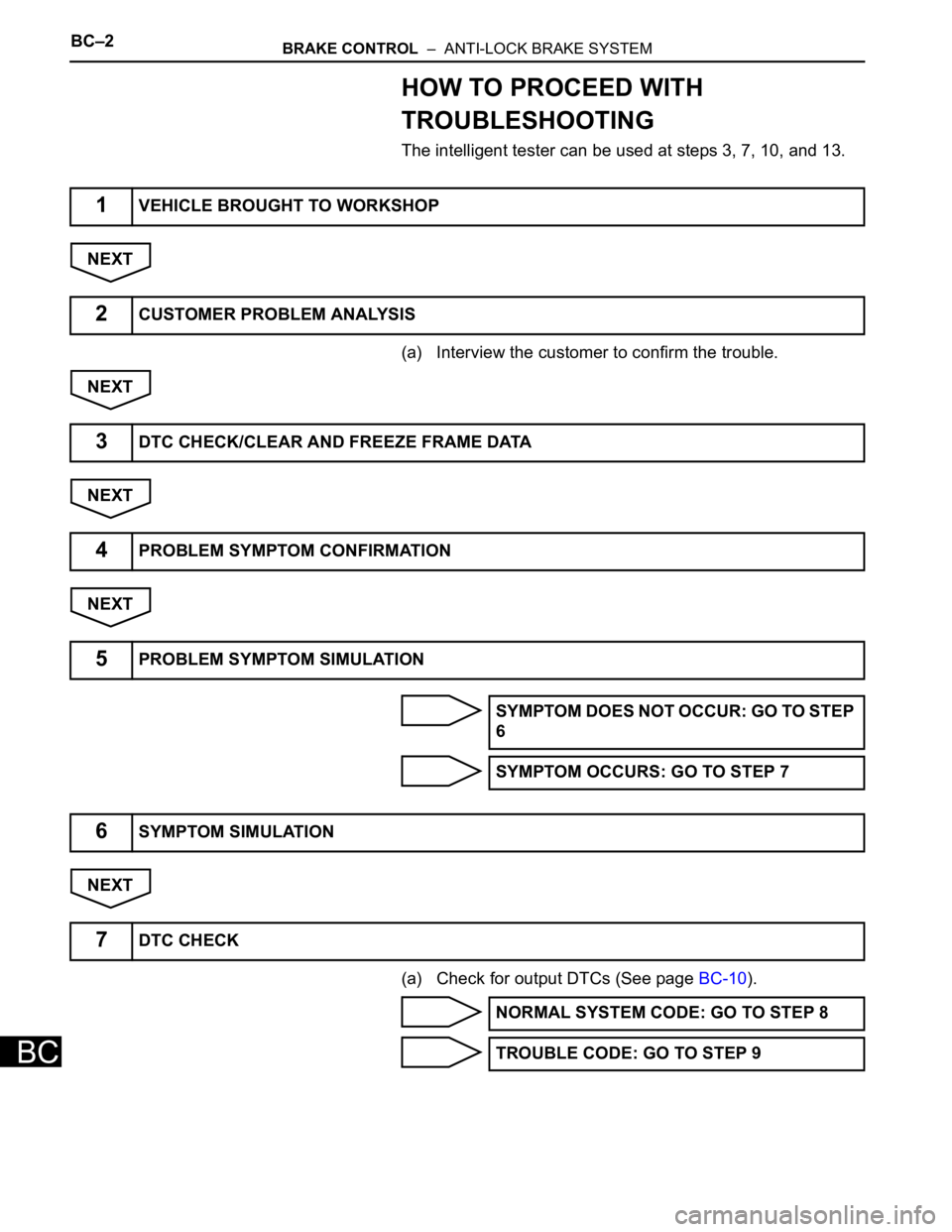
HOW TO PROCEED WITH
TROUBLESHOOTING
The intelligent tester can be used at steps 3, 7, 10, and 13.
NEXT
(a) Interview the customer to confirm the trouble.
NEXT
NEXT
NEXT
NEXT
(a) Check for output DTCs (See page BC-10).
1VEHICLE BROUGHT TO WORKSHOP
2CUSTOMER PROBLEM ANALYSIS
3DTC CHECK/CLEAR AND FREEZE FRAME DATA
4PROBLEM SYMPTOM CONFIRMATION
5PROBLEM SYMPTOM SIMULATION
SYMPTOM DOES NOT OCCUR: GO TO STEP
6
SYMPTOM OCCURS: GO TO STEP 7
6SYMPTOM SIMULATION
7DTC CHECK
NORMAL SYSTEM CODE: GO TO STEP 8
TROUBLE CODE: GO TO STEP 9
Page 2367 of 3000
BRAKE CONTROL – ANTI-LOCK BRAKE SYSTEMBC–3
BC
NEXT
NEXT
NEXT
NEXT
NEXT
NEXT
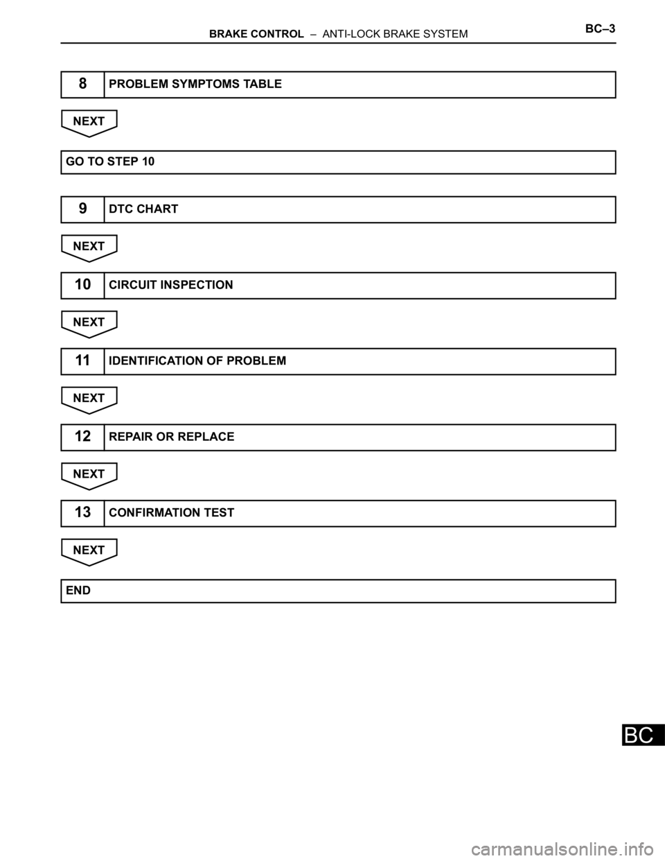
8PROBLEM SYMPTOMS TABLE
GO TO STEP 10
9DTC CHART
10CIRCUIT INSPECTION
11IDENTIFICATION OF PROBLEM
12REPAIR OR REPLACE
13CONFIRMATION TEST
END
Page 2368 of 3000
BC–4BRAKE CONTROL – ANTI-LOCK BRAKE SYSTEM
BC
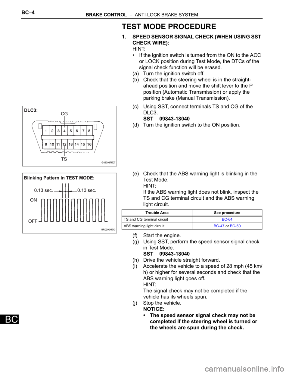
TEST MODE PROCEDURE
1. SPEED SENSOR SIGNAL CHECK (WHEN USING SST
CHECK WIRE):
HINT:
• If the ignition switch is turned from the ON to the ACC
or LOCK position during Test Mode, the DTCs of the
signal check function will be erased.
(a) Turn the ignition switch off.
(b) Check that the steering wheel is in the straight-
ahead position and move the shift lever to the P
position (Automatic Transmission) or apply the
parking brake (Manual Transmission).
(c) Using SST, connect terminals TS and CG of the
DLC3.
SST 09843-18040
(d) Turn the ignition switch to the ON position.
(e) Check that the ABS warning light is blinking in the
Test Mode.
HINT:
If the ABS warning light does not blink, inspect the
TS and CG terminal circuit and the ABS warning
light circuit.
(f) Start the engine.
(g) Using SST, perform the speed sensor signal check
in Test Mode.
SST 09843-18040
(h) Drive the vehicle straight forward.
(i) Accelerate the vehicle to a speed of 28 mph (45 km/
h) or higher for several seconds and check that the
ABS warning light goes off.
HINT:
The signal check may not be completed if the
vehicle has its wheels spun.
(j) Stop the vehicle.
NOTICE:
• The speed sensor signal check may not be
completed if the steering wheel is turned or
the wheels are spun during the check.
G022987E07
BR03904E13
Trouble Area See procedure
TS and CG terminal circuitBC-64
ABS warning light circuitBC-47 or BC-50
Page 2369 of 3000
BRAKE CONTROL – ANTI-LOCK BRAKE SYSTEMBC–5
BC
• After the ABS warning light goes off and if
vehicle speed exceeds 50 mph (80 km/h), the
signal check code will be stored again.
Decelerate or stop the vehicle before the
speed reaches 50 mph (80 km/h).
• If the signal check has not been completed,
the ABS warning light blinks while driving
and the ABS system does not operate.
HINT:
When the signal check has been completed, the
ABS warning light goes off while driving and blinks
in the Test Mode pattern while stationary.
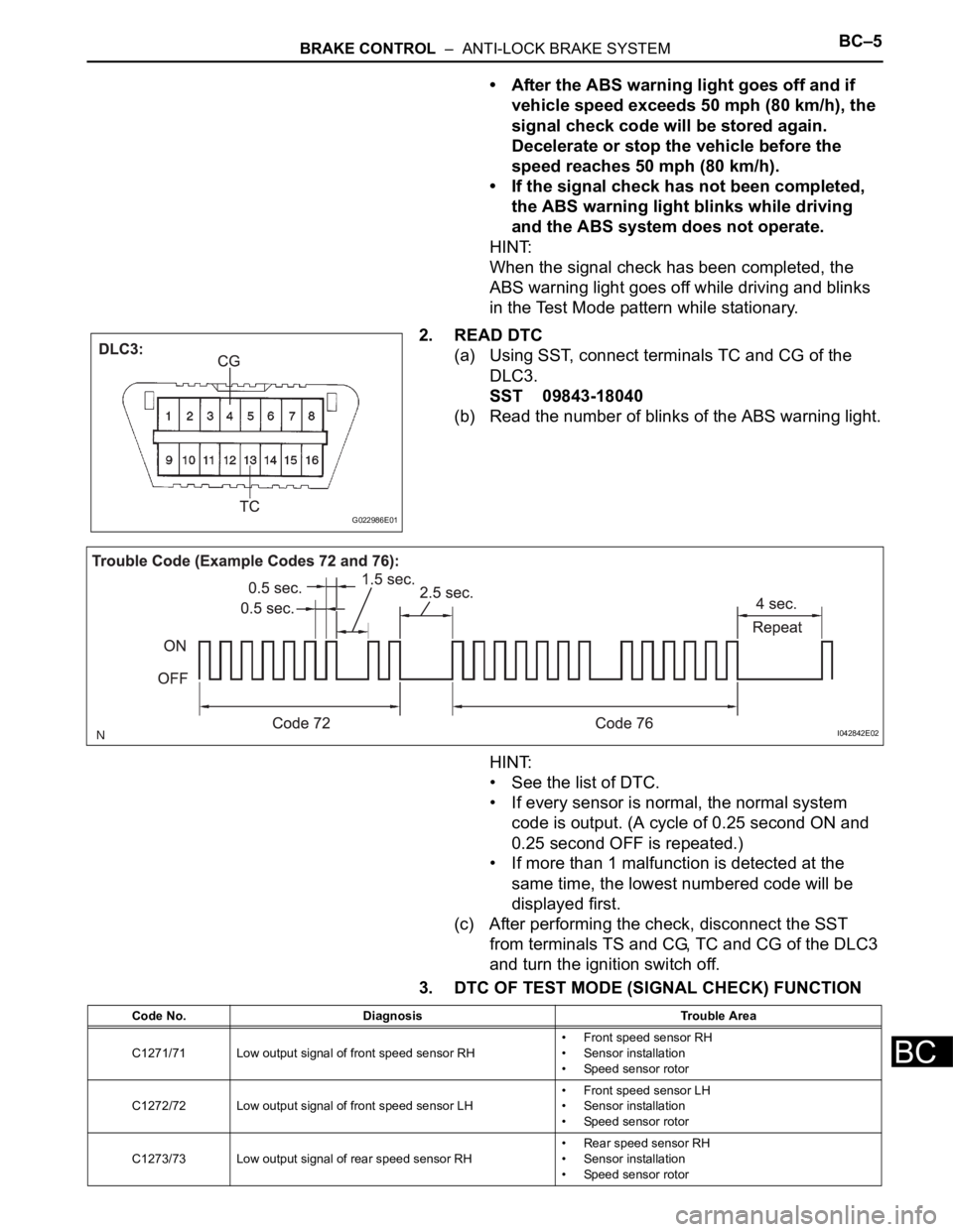
2. READ DTC
(a) Using SST, connect terminals TC and CG of the
DLC3.
SST 09843-18040
(b) Read the number of blinks of the ABS warning light.
HINT:
• See the list of DTC.
• If every sensor is normal, the normal system
code is output. (A cycle of 0.25 second ON and
0.25 second OFF is repeated.)
• If more than 1 malfunction is detected at the
same time, the lowest numbered code will be
displayed first.
(c) After performing the check, disconnect the SST
from terminals TS and CG, TC and CG of the DLC3
and turn the ignition switch off.
3. DTC OF TEST MODE (SIGNAL CHECK) FUNCTION
G022986E01
I042842E02
Code No. Diagnosis Trouble Area
C1271/71 Low output signal of front speed sensor RH• Front speed sensor RH
• Sensor installation
• Speed sensor rotor
C1272/72 Low output signal of front speed sensor LH• Front speed sensor LH
• Sensor installation
• Speed sensor rotor
C1273/73 Low output signal of rear speed sensor RH• Rear speed sensor RH
• Sensor installation
• Speed sensor rotor
Page 2370 of 3000
BC–6BRAKE CONTROL – ANTI-LOCK BRAKE SYSTEM
BC
HINT:
The codes in this table are output only in Test Mode
(signal check).
4. SPEED SENSOR SIGNAL CHECK (WHEN USING
INTELLIGENT TESTER):
HINT:
• If the ignition switch is turned from the ON to the ACC
or LOCK position during Test Mode, DTCs of the
signal check function will be erased.
• During Test Mode, the ECU records all DTCs of the
signal check function. By performing the signal check,
the codes are erased if normality is confirmed. The
remaining codes are the codes where an abnormality
was found.
(a) Turn the ignition switch off.
(b) Check that the steering wheel is in the straight-
ahead position.
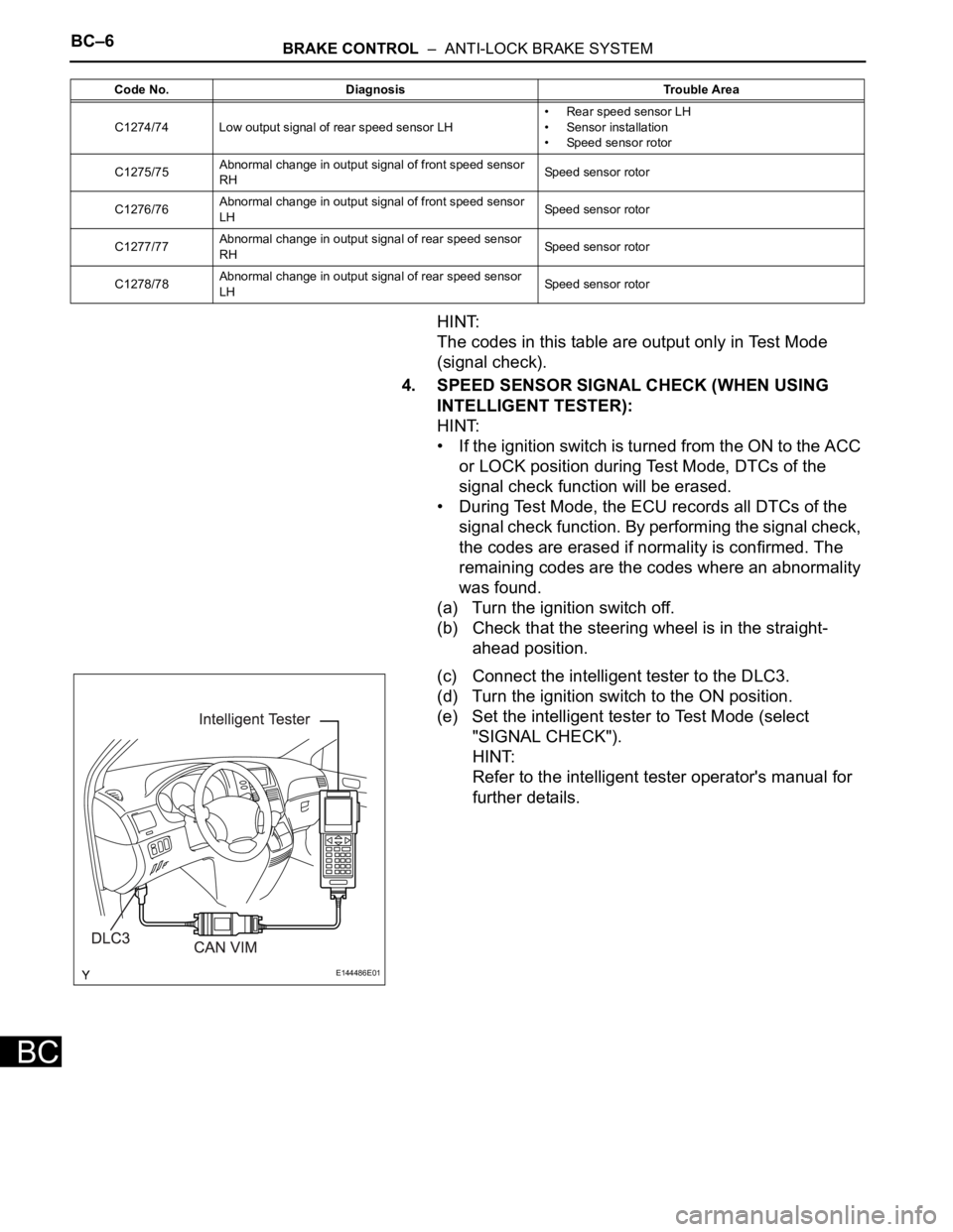
(c) Connect the intelligent tester to the DLC3.
(d) Turn the ignition switch to the ON position.
(e) Set the intelligent tester to Test Mode (select
"SIGNAL CHECK").
HINT:
Refer to the intelligent tester operator's manual for
further details.
C1274/74 Low output signal of rear speed sensor LH• Rear speed sensor LH
• Sensor installation
• Speed sensor rotor
C1275/75Abnormal change in output signal of front speed sensor
RHSpeed sensor rotor
C1276/76Abnormal change in output signal of front speed sensor
LHSpeed sensor rotor
C1277/77Abnormal change in output signal of rear speed sensor
RHSpeed sensor rotor
C1278/78Abnormal change in output signal of rear speed sensor
LHSpeed sensor rotor Code No. Diagnosis Trouble Area
E144486E01