air filter TOYOTA SIENNA 2007 Service Repair Manual
[x] Cancel search | Manufacturer: TOYOTA, Model Year: 2007, Model line: SIENNA, Model: TOYOTA SIENNA 2007Pages: 3000, PDF Size: 52.26 MB
Page 27 of 3000
EM–282GR-FE ENGINE MECHANICAL – ENGINE ASSEMBLY
EM
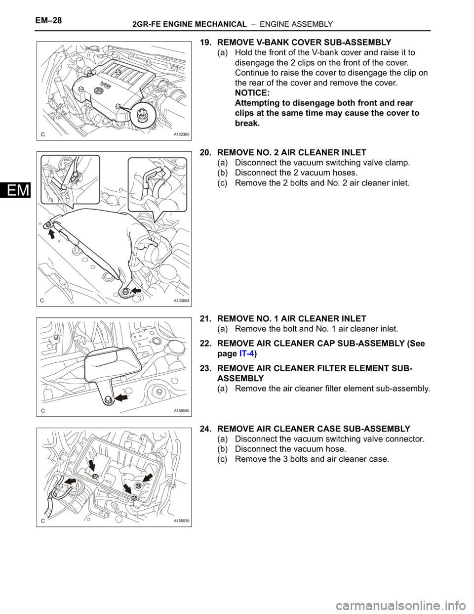
19. REMOVE V-BANK COVER SUB-ASSEMBLY
(a) Hold the front of the V-bank cover and raise it to
disengage the 2 clips on the front of the cover.
Continue to raise the cover to disengage the clip on
the rear of the cover and remove the cover.
NOTICE:
Attempting to disengage both front and rear
clips at the same time may cause the cover to
break.
20. REMOVE NO. 2 AIR CLEANER INLET
(a) Disconnect the vacuum switching valve clamp.
(b) Disconnect the 2 vacuum hoses.
(c) Remove the 2 bolts and No. 2 air cleaner inlet.
21. REMOVE NO. 1 AIR CLEANER INLET
(a) Remove the bolt and No. 1 air cleaner inlet.
22. REMOVE AIR CLEANER CAP SUB-ASSEMBLY (See
page IT-4)
23. REMOVE AIR CLEANER FILTER ELEMENT SUB-
ASSEMBLY
(a) Remove the air cleaner filter element sub-assembly.
24. REMOVE AIR CLEANER CASE SUB-ASSEMBLY
(a) Disconnect the vacuum switching valve connector.
(b) Disconnect the vacuum hose.
(c) Remove the 3 bolts and air cleaner case.
A162365
A133004
A155040
A155039
Page 46 of 3000
2GR-FE INTAKE – INTAKE AIR CONTROL VALVEIT–5
IT
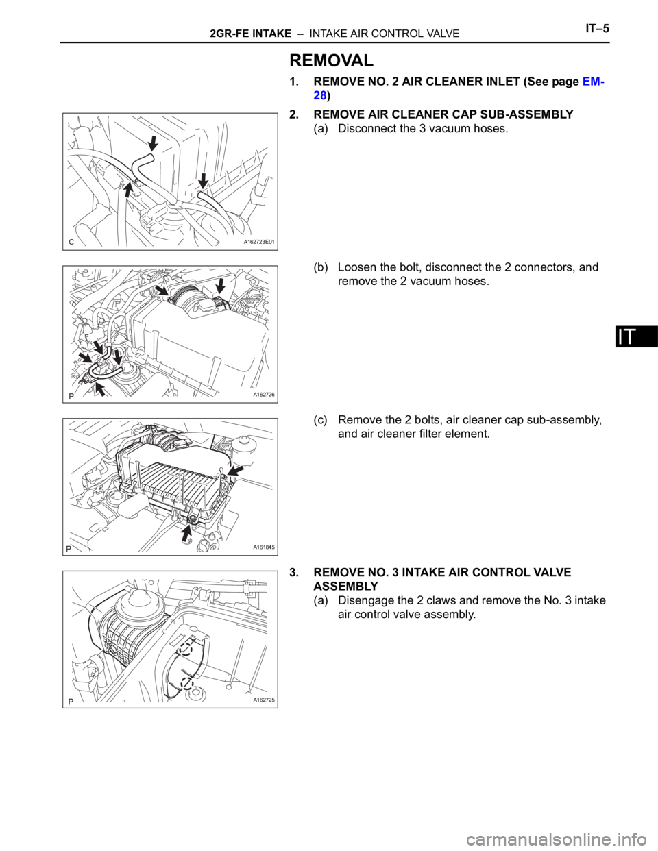
REMOVAL
1. REMOVE NO. 2 AIR CLEANER INLET (See page EM-
28)
2. REMOVE AIR CLEANER CAP SUB-ASSEMBLY
(a) Disconnect the 3 vacuum hoses.
(b) Loosen the bolt, disconnect the 2 connectors, and
remove the 2 vacuum hoses.
(c) Remove the 2 bolts, air cleaner cap sub-assembly,
and air cleaner filter element.
3. REMOVE NO. 3 INTAKE AIR CONTROL VALVE
ASSEMBLY
(a) Disengage the 2 claws and remove the No. 3 intake
air control valve assembly.
A162723E01
A162726
A161845
A162725
Page 47 of 3000
IT–62GR-FE INTAKE – INTAKE AIR CONTROL VALVE
IT
INSPECTION
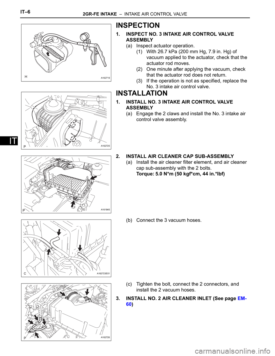
1. INSPECT NO. 3 INTAKE AIR CONTROL VALVE
ASSEMBLY
(a) Inspect actuator operation.
(1) With 26.7 kPa (200 mm Hg, 7.9 in. Hg) of
vacuum applied to the actuator, check that the
actuator rod moves.
(2) One minute after applying the vacuum, check
that the actuator rod does not return.
(3) If the operation is not as specified, replace the
No. 3 intake air control valve.
INSTALLATION
1. INSTALL NO. 3 INTAKE AIR CONTROL VALVE
ASSEMBLY
(a) Engage the 2 claws and install the No. 3 intake air
control valve assembly.
2. INSTALL AIR CLEANER CAP SUB-ASSEMBLY
(a) Install the air cleaner filter element, and air cleaner
cap sub-assembly with the 2 bolts.
Torque: 5.0 N*m (50 kgf*cm, 44 in.*lbf)
(b) Connect the 3 vacuum hoses.
(c) Tighten the bolt, connect the 2 connectors, and
install the 2 vacuum hoses.
3. INSTALL NO. 2 AIR CLEANER INLET (See page EM-
60)
A162719
A162725
A161845
A162723E01
A162726
Page 58 of 3000

INTRODUCTION – TERMSIN–51
IN
IFI Indirect Fuel Injection Indirect Injection (IDL)
IFS Inertia Fuel-Shutoff -
ISC Idle Speed Control -
KS Knock Sensor Knock Sensor
MAF Mass Airflow Air Flow Meter
MAP Manifold Absolute Pressure Manifold Pressure Intake Vacuum
MC Mixture ControlElectric Bleed Air Control Valve (EBCV)
Mixture Control Valve (MCV)
Electric Air Control Valve (EACV)
MDP Manifold Differential Pressure -
MFI Multiport Fuel Injection Electronic Fuel Injection (EFI)
MIL Malfunction Indicator Light Check Engine Light
MST Manifold Surface Temperature -
MVZ Manifold Vacuum Zone -
NVRAM Non-Volatile Random Access Memory -
O2S Oxygen SensorOxygen Sensor, O
2 Sensor (O2S)
OBD On-Board Diagnostic On-Board Diagnostic System (OBD)
OC Oxidation Catalytic Converter Oxidation Catalytic Convert (OC), CCo
OL Open Loop Open Loop
PAIR Pulsed Secondary Air Injection Air Suction (AS)
PCM Powertrain Control Module -
PNP Park/Neutral Position -
PROM Programmable Read Only Memory -
PSP Power Steering Pressure -
PTOX Periodic Trap OxidizerDiesel Particulate Filter (DPF)
Diesel Particulate Trap (DPT)
RAM Random Access Memory Random Access Memory (RAM)
RM Relay Module -
ROM Read Only Memory Read Only Memory (ROM)
RPM Engine Speed Engine Speed
SC Supercharger Supercharger
SCB Supercharger Bypass E-ABV
SFI Sequential Multiport Fuel Injection Electronic Fuel Injection (EFI), Sequential Injection
SPL Smoke Puff Limiter -
SRI Service Reminder Indicator -
SRT System Readiness Test -
ST Scan Tool -
TB Throttle Body Throttle Body
TBI Throttle Body Fuel InjectionSingle Point Injection
Central Fuel Injection (Ci)
TC Turbocharger Turbocharger
TCC Torque Converter Clutch Torque Converter
TCM Transmission Control Module Transmission ECU, ECT ECU
TP Throttle Position Throttle Position
TR Transmission Range -
TVV Thermal Vacuum ValveBimetallic Vacuum Switching Valve (BVSV)
Thermostatic Vacuum Switching Valve (TVSV)
TWC Three-Way Catalytic ConverterThree-Way Catalytic (TWC)
Manifold Converter
CC
RO
SAE
ABBREVIATIONSSAE TERMSTOYOTA TERMS
( )-ABBREVIATIONS
Page 83 of 3000
2GR-FE STARTING – STARTERST–5
ST
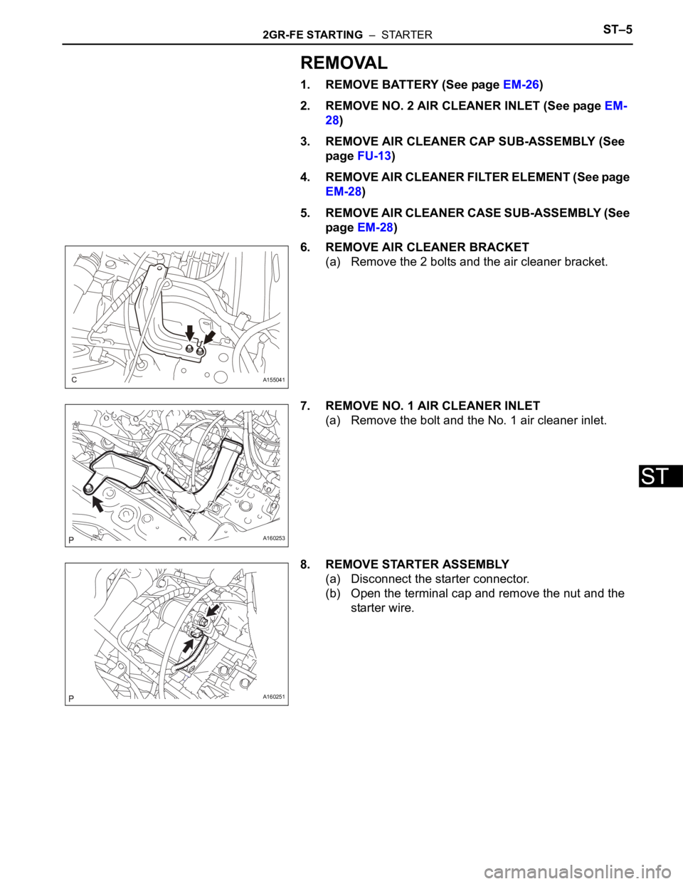
REMOVAL
1. REMOVE BATTERY (See page EM-26)
2. REMOVE NO. 2 AIR CLEANER INLET (See page EM-
28)
3. REMOVE AIR CLEANER CAP SUB-ASSEMBLY (See
page FU-13)
4. REMOVE AIR CLEANER FILTER ELEMENT (See page
EM-28)
5. REMOVE AIR CLEANER CASE SUB-ASSEMBLY (See
page EM-28)
6. REMOVE AIR CLEANER BRACKET
(a) Remove the 2 bolts and the air cleaner bracket.
7. REMOVE NO. 1 AIR CLEANER INLET
(a) Remove the bolt and the No. 1 air cleaner inlet.
8. REMOVE STARTER ASSEMBLY
(a) Disconnect the starter connector.
(b) Open the terminal cap and remove the nut and the
starter wire.
A155041
A160253
A160251
Page 341 of 3000
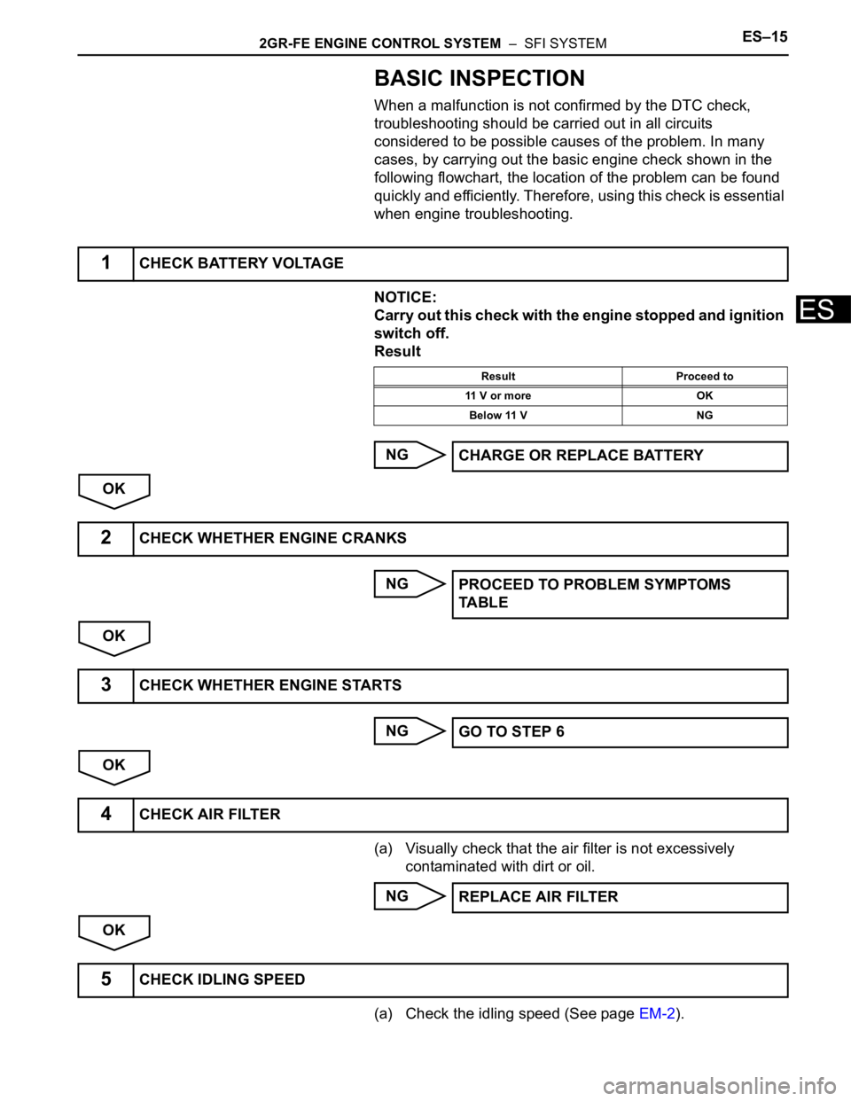
2GR-FE ENGINE CONTROL SYSTEM – SFI SYSTEMES–15
ES
BASIC INSPECTION
When a malfunction is not confirmed by the DTC check,
troubleshooting should be carried out in all circuits
considered to be possible causes of the problem. In many
cases, by carrying out the basic engine check shown in the
following flowchart, the location of the problem can be found
quickly and efficiently. Therefore, using this check is essential
when engine troubleshooting.
NOTICE:
Carry out this check with the engine stopped and ignition
switch off.
Result
NG
OK
NG
OK
NG
OK
(a) Visually check that the air filter is not excessively
contaminated with dirt or oil.
NG
OK
(a) Check the idling speed (See page EM-2).
1CHECK BATTERY VOLTAGE
Result Proceed to
11 V or more OK
Below 11 V NG
CHARGE OR REPLACE BATTERY
2CHECK WHETHER ENGINE CRANKS
PROCEED TO PROBLEM SYMPTOMS
TA B L E
3CHECK WHETHER ENGINE STARTS
GO TO STEP 6
4CHECK AIR FILTER
REPLACE AIR FILTER
5CHECK IDLING SPEED
Page 383 of 3000
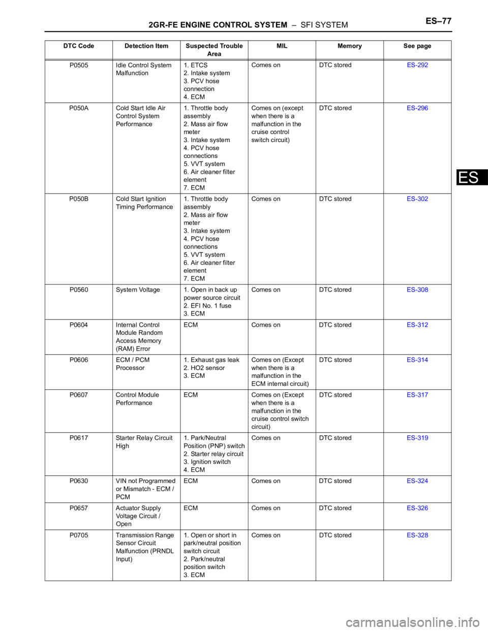
2GR-FE ENGINE CONTROL SYSTEM – SFI SYSTEMES–77
ES
P0505 Idle Control System
Malfunction1. ETCS
2. Intake system
3. PCV hose
connection
4. ECMComes on DTC storedES-292
P050A Cold Start Idle Air
Control System
Performance1. Throttle body
assembly
2. Mass air flow
meter
3. Intake system
4. PCV hose
connections
5. VVT system
6. Air cleaner filter
element
7. ECMComes on (except
when there is a
malfunction in the
cruise control
switch circuit)DTC storedES-296
P050B Cold Start Ignition
Timing Performance1. Throttle body
assembly
2. Mass air flow
meter
3. Intake system
4. PCV hose
connections
5. VVT system
6. Air cleaner filter
element
7. ECMComes on DTC storedES-302
P0560 System Voltage 1. Open in back up
power source circuit
2. EFI No. 1 fuse
3. ECMComes on DTC storedES-308
P0604 Internal Control
Module Random
Access Memory
(RAM) ErrorECM Comes on DTC storedES-312
P0606 ECM / PCM
Processor1. Exhaust gas leak
2. HO2 sensor
3. ECMComes on (Except
when there is a
malfunction in the
ECM internal circuit)DTC storedES-314
P0607 Control Module
PerformanceECM Comes on (Except
when there is a
malfunction in the
cruise control switch
circuit)DTC storedES-317
P0617 Starter Relay Circuit
High1. Park/Neutral
Position (PNP) switch
2. Starter relay circuit
3. Ignition switch
4. ECMComes on DTC storedES-319
P0630 VIN not Programmed
or Mismatch - ECM /
PCMECM Comes on DTC storedES-324
P0657 Actuator Supply
Voltage Circuit /
OpenECM Comes on DTC storedES-326
P0705 Transmission Range
Sensor Circuit
Malfunction (PRNDL
Input)1. Open or short in
park/neutral position
switch circuit
2. Park/neutral
position switch
3. ECMComes on DTC storedES-328 DTC Code Detection Item Suspected Trouble
AreaMIL Memory See page
Page 520 of 3000
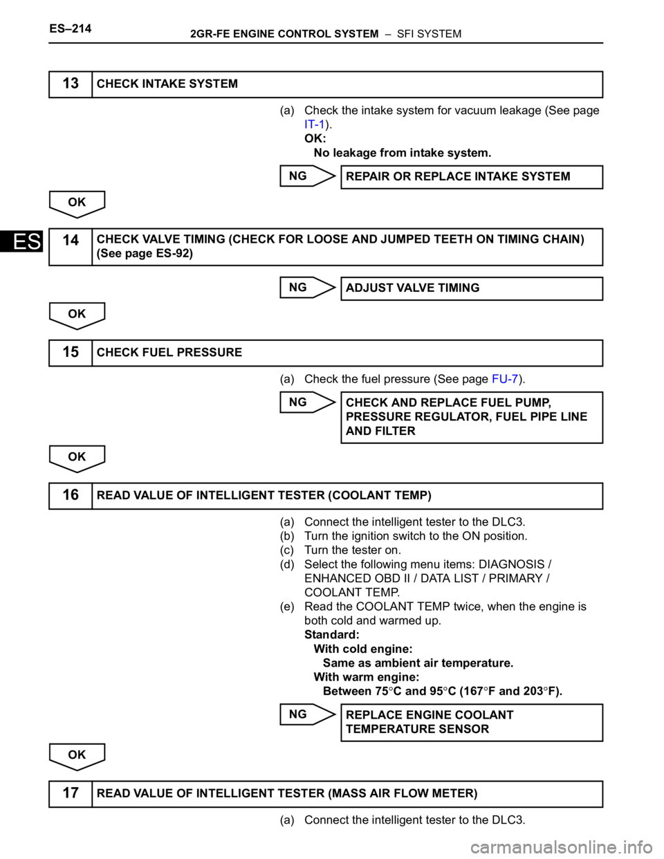
ES–2142GR-FE ENGINE CONTROL SYSTEM – SFI SYSTEM
ES
(a) Check the intake system for vacuum leakage (See page
IT-1).
OK:
No leakage from intake system.
NG
OK
NG
OK
(a) Check the fuel pressure (See page FU-7).
NG
OK
(a) Connect the intelligent tester to the DLC3.
(b) Turn the ignition switch to the ON position.
(c) Turn the tester on.
(d) Select the following menu items: DIAGNOSIS /
ENHANCED OBD II / DATA LIST / PRIMARY /
COOLANT TEMP.
(e) Read the COOLANT TEMP twice, when the engine is
both cold and warmed up.
Standard:
With cold engine:
Same as ambient air temperature.
With warm engine:
Between 75
C and 95C (167F and 203F).
NG
OK
(a) Connect the intelligent tester to the DLC3.
13CHECK INTAKE SYSTEM
REPAIR OR REPLACE INTAKE SYSTEM
14CHECK VALVE TIMING (CHECK FOR LOOSE AND JUMPED TEETH ON TIMING CHAIN)
(See page ES-92)
ADJUST VALVE TIMING
15CHECK FUEL PRESSURE
CHECK AND REPLACE FUEL PUMP,
PRESSURE REGULATOR, FUEL PIPE LINE
AND FILTER
16READ VALUE OF INTELLIGENT TESTER (COOLANT TEMP)
REPLACE ENGINE COOLANT
TEMPERATURE SENSOR
17READ VALUE OF INTELLIGENT TESTER (MASS AIR FLOW METER)
Page 521 of 3000
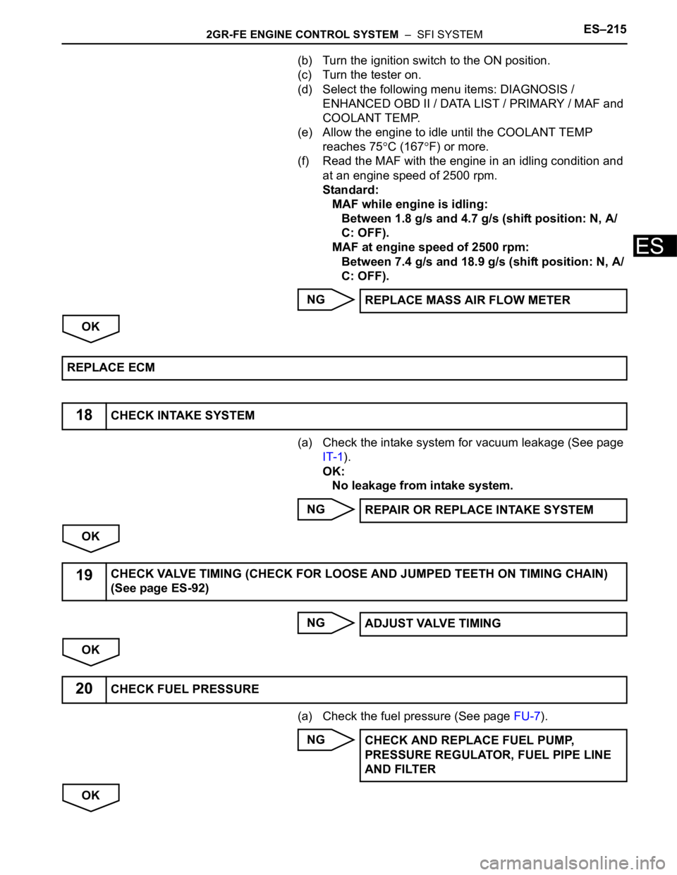
2GR-FE ENGINE CONTROL SYSTEM – SFI SYSTEMES–215
ES
(b) Turn the ignition switch to the ON position.
(c) Turn the tester on.
(d) Select the following menu items: DIAGNOSIS /
ENHANCED OBD II / DATA LIST / PRIMARY / MAF and
COOLANT TEMP.
(e) Allow the engine to idle until the COOLANT TEMP
reaches 75
C (167F) or more.
(f) Read the MAF with the engine in an idling condition and
at an engine speed of 2500 rpm.
Standard:
MAF while engine is idling:
Between 1.8 g/s and 4.7 g/s (shift position: N, A/
C: OFF).
MAF at engine speed of 2500 rpm:
Between 7.4 g/s and 18.9 g/s (shift position: N, A/
C: OFF).
NG
OK
(a) Check the intake system for vacuum leakage (See page
IT-1).
OK:
No leakage from intake system.
NG
OK
NG
OK
(a) Check the fuel pressure (See page FU-7).
NG
OKREPLACE MASS AIR FLOW METER
REPLACE ECM
18CHECK INTAKE SYSTEM
REPAIR OR REPLACE INTAKE SYSTEM
19CHECK VALVE TIMING (CHECK FOR LOOSE AND JUMPED TEETH ON TIMING CHAIN)
(See page ES-92)
ADJUST VALVE TIMING
20CHECK FUEL PRESSURE
CHECK AND REPLACE FUEL PUMP,
PRESSURE REGULATOR, FUEL PIPE LINE
AND FILTER
Page 577 of 3000
ES–2842GR-FE ENGINE CONTROL SYSTEM – SFI SYSTEM
ES
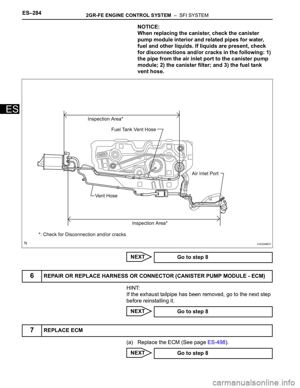
NOTICE:
When replacing the canister, check the canister
pump module interior and related pipes for water,
fuel and other liquids. If liquids are present, check
for disconnections and/or cracks in the following: 1)
the pipe from the air inlet port to the canister pump
module; 2) the canister filter; and 3) the fuel tank
vent hose.
NEXT
HINT:
If the exhaust tailpipe has been removed, go to the next step
before reinstalling it.
NEXT
(a) Replace the ECM (See page ES-498).
NEXT
A163294E01
Go to step 8
6REPAIR OR REPLACE HARNESS OR CONNECTOR (CANISTER PUMP MODULE - ECM)
Go to step 8
7REPLACE ECM
Go to step 8