warning TOYOTA SIENNA 2007 Service Repair Manual
[x] Cancel search | Manufacturer: TOYOTA, Model Year: 2007, Model line: SIENNA, Model: TOYOTA SIENNA 2007Pages: 3000, PDF Size: 52.26 MB
Page 50 of 3000

IN–38INTRODUCTION – HOW TO TROUBLESHOOT ECU CONTROLLED SYSTEMS
IN
HINT:
• In troubleshooting, confirm that the problem symptoms
have been accurately identified. Preconceptions should be
discarded in order to make an accurate judgment. To
clearly understand what the problem symptoms are, it is
extremely important to ask the customer about the
problem and the conditions at the time the malfunction
occurred.
• Gather as much information as possible for reference.
Past problems that seem unrelated may also help in some
cases.
• The following 5 items are important points in the problem
analysis:
3. SYMPTOM CONFIRMATION AND DIAGNOSTIC
TROUBLE CODE
HINT:
The diagnostic system in the SIENNA has various
functions.
• The first function is the Diagnostic Trouble Code
(DTC) check. A DTC is a code stored in the ECU
memory whenever a malfunction in the signal circuits
to the ECU occurs. In a DTC check, a previous
malfunction's DTC can be checked by a technician
during troubleshooting.
• Another function is the Input Signal Check, which
checks if the signals from various switches are sent to
the ECU correctly.
By using these functions, the problem areas can be
narrowed down and troubleshooting is more effective.
Diagnostic functions are incorporated in the following
system in the SIENNA.
What Vehicle model, system name
When Date, time, occurrence frequency
Where Road conditions
Under what conditions? Running conditions, driving conditions, weather conditions
How did it happen? Problem symptoms
SystemSYMPTOM CONFIRMATION AND DIAGNOSTIC TROUBLE CODE
DTC Check
(Normal Mode)DTC Check
(Check Mode)Sensor Check/
Test Mode
(Input Signal
Check)Data List Active Test
2GR-FE SFI System
X
U151E Automatic Transaxle SystemX
U151F Automatic Transaxle SystemX
Tire pressure warning systemXX
Anti-lock Brake System
X
Vehicle Stability Control SystemX
Air Conditioning System (for Manual Air
Conditioning System)XXXXX
Air Conditioning System (for Automatic Air
Conditioning System)
XX
Airbag SystemXX
Occupant Classification System
XXX
Page 51 of 3000

INTRODUCTION – HOW TO TROUBLESHOOT ECU CONTROLLED SYSTEMSIN–39
IN
• In the DTC check, it is very important to determine
whether the problem indicated by the DTC either: 1)
still occurs, or 2) occurred in the past but has returned
to normal. In addition, the DTC should be compared
to the problem symptom to see if they are related. For
this reason, DTCs should be checked before and after
confirmation of symptoms (i.e., whether or not
problem symptoms exist) to determine current system
conditions, as shown in the flowchart below.
• Never skip the DTC check. Failing to check DTCs
may, depending on the case, result in unnecessary
troubleshooting for systems operating normally or
lead to repairs not related to the problem. Follow the
procedures listed in the flowchart in the correct order.
Theft Deterrent System XXXXX
Engine Immobiliser System
XX
Cruise Control SystemXXX
Dynamic Laser Cruise Control System
XXX
Lighting System
XX
Wiper and Washer SystemXXXXX
Power Door Lock Control System X X X
Wireless Door Lock Control SystemXX
Key Reminder Warning System X X XX
Meter / Gauge System X X X
Audio and Visual SystemXXXX
Rear Seat Entertainment System XXXXX
Navigation System
XXXX
Clearance Sonar SystemXXXXX
Rear View Monitor System XXXXX
Power Window Control System (with Jam
Protection Function)XXX
Power Window Control System (without Jam
Protection Function)XXXXX
Power Mirror Control System (with Memory) X X X
Power Mirror Control System (without Memory)XXXXX
Front Power Seat Control System X X X
Rear No. 2 Seat Assembly (with Power Stowing
Function)XXXXX
Window Deogger SystemXXXXX
Power Slide Door System
XX
Slide Door Closer System X X X
Back Door Closer SystemXX
Power Back Door SystemXX
Sliding Roof System XXXXX
Multiplex Communication System XXXXX
CAN Communication System XXXXXSystemSYMPTOM CONFIRMATION AND DIAGNOSTIC TROUBLE CODE
DTC Check
(Normal Mode)DTC Check
(Check Mode)Sensor Check/
Test Mode
(Input Signal
Check)Data List Active Test
Page 68 of 3000

IN–38INTRODUCTION – HOW TO TROUBLESHOOT ECU CONTROLLED SYSTEMS
IN
HINT:
• In troubleshooting, confirm that the problem symptoms
have been accurately identified. Preconceptions should be
discarded in order to make an accurate judgment. To
clearly understand what the problem symptoms are, it is
extremely important to ask the customer about the
problem and the conditions at the time the malfunction
occurred.
• Gather as much information as possible for reference.
Past problems that seem unrelated may also help in some
cases.
• The following 5 items are important points in the problem
analysis:
3. SYMPTOM CONFIRMATION AND DIAGNOSTIC
TROUBLE CODE
HINT:
The diagnostic system in the SIENNA has various
functions.
• The first function is the Diagnostic Trouble Code
(DTC) check. A DTC is a code stored in the ECU
memory whenever a malfunction in the signal circuits
to the ECU occurs. In a DTC check, a previous
malfunction's DTC can be checked by a technician
during troubleshooting.
• Another function is the Input Signal Check, which
checks if the signals from various switches are sent to
the ECU correctly.
By using these functions, the problem areas can be
narrowed down and troubleshooting is more effective.
Diagnostic functions are incorporated in the following
system in the SIENNA.
What Vehicle model, system name
When Date, time, occurrence frequency
Where Road conditions
Under what conditions? Running conditions, driving conditions, weather conditions
How did it happen? Problem symptoms
SystemSYMPTOM CONFIRMATION AND DIAGNOSTIC TROUBLE CODE
DTC Check
(Normal Mode)DTC Check
(Check Mode)Sensor Check/
Test Mode
(Input Signal
Check)Data List Active Test
2GR-FE SFI System
X
U151E Automatic Transaxle SystemX
U151F Automatic Transaxle SystemX
Tire pressure warning systemXX
Anti-lock Brake System
X
Vehicle Stability Control SystemX
Air Conditioning System (for Manual Air
Conditioning System)XXXXX
Air Conditioning System (for Automatic Air
Conditioning System)
XX
Airbag SystemXX
Occupant Classification System
XXX
Page 69 of 3000

INTRODUCTION – HOW TO TROUBLESHOOT ECU CONTROLLED SYSTEMSIN–39
IN
• In the DTC check, it is very important to determine
whether the problem indicated by the DTC either: 1)
still occurs, or 2) occurred in the past but has returned
to normal. In addition, the DTC should be compared
to the problem symptom to see if they are related. For
this reason, DTCs should be checked before and after
confirmation of symptoms (i.e., whether or not
problem symptoms exist) to determine current system
conditions, as shown in the flowchart below.
• Never skip the DTC check. Failing to check DTCs
may, depending on the case, result in unnecessary
troubleshooting for systems operating normally or
lead to repairs not related to the problem. Follow the
procedures listed in the flowchart in the correct order.
Theft Deterrent System XXXXX
Engine Immobiliser System
XX
Cruise Control SystemXXX
Dynamic Laser Cruise Control System
XXX
Lighting System
XX
Wiper and Washer SystemXXXXX
Power Door Lock Control System X X X
Wireless Door Lock Control SystemXX
Key Reminder Warning System X X XX
Meter / Gauge System X X X
Audio and Visual SystemXXXX
Rear Seat Entertainment System XXXXX
Navigation System
XXXX
Clearance Sonar SystemXXXXX
Rear View Monitor System XXXXX
Power Window Control System (with Jam
Protection Function)XXX
Power Window Control System (without Jam
Protection Function)XXXXX
Power Mirror Control System (with Memory) X X X
Power Mirror Control System (without Memory)XXXXX
Front Power Seat Control System X X X
Rear No. 2 Seat Assembly (with Power Stowing
Function)XXXXX
Window Deogger SystemXXXXX
Power Slide Door System
XX
Slide Door Closer System X X X
Back Door Closer SystemXX
Power Back Door SystemXX
Sliding Roof System XXXXX
Multiplex Communication System XXXXX
CAN Communication System XXXXXSystemSYMPTOM CONFIRMATION AND DIAGNOSTIC TROUBLE CODE
DTC Check
(Normal Mode)DTC Check
(Check Mode)Sensor Check/
Test Mode
(Input Signal
Check)Data List Active Test
Page 87 of 3000

2GR-FE CHARGING – CHARGING SYSTEMCH–5
CH
PROBLEM SYMPTOMS TABLE
Result
Symptom Suspected Area See page
Charge Warning Light Comes ON while DrivingClutch pulley
CH-8
Generator assembly
Noise Occurs from Generator while Engine is RunningV-ribbed belt
CH-9 Clutch pulley
Generator assembly
Page 175 of 3000

TIRE AND WHEEL – TIRE AND WHEEL SYSTEMTW–5
TW
REPAIR
1. INTRODUCTION
(a) This section introduces ways to determine whether
the run-flat tire is repairable or not. Repair must be
performed by following the appropriate procedures.
If a flat tire occurs, it is possible to drive a maximum
of 160 km (100 miles) at a speed below 90 km/h (55
mph) due to the reinforced sidewalls. However, if
the customer continues to drive with low tire
pressure (less than about 100 kPa (1.0 kgf/cm
2,
14.5 psi) and tire pressure warning light is on), the
inside of the sidewall will gradually deteriorate and
the run-flat performance may be reduced.
Therefore, the tires may require replacement.
However, there are some cases where it is possible
to repair a run-flat tire using the same repair method
as for normal tires. Use the following flowchart to
determine if a run-flat tire is repairable.
NOTICE:
When performing repairs, follow the Rubber
Manufacturers Association (RMA) repair
procedures.
2. REPAIR PROCEDURE (CUSTOMER INTERVIEW)
(a) The tire pressure warning system can help
determine the history of the tire's use. The driving
conditions the tire was subjected to while the tire
pressure warning light was on should be obtained
from the customer. Also, make sure to ask the
following questions.
(1) Was the vehicle driven at a speed over 90 km/h
(55 mph) with the tire pressure warning light
on?
(2) Was the vehicle driven over 160 km (100 miles)
with the tire pressure warning light on?
A "Yes" response to either of the above will
greatly reduce the chance of tire repairability.
3. TECHNICIAN TIRE INSPECTION
(a) After the customer interview, it is necessary to
conduct a thorough inspection of the tire after it has
been removed from the wheel. As it is difficult to
identify a tire with low pressure visually, check the
pressure of each tire to determine the tire(s) causing
the low-pressure warning. If the tire is found to be
repairable, follow the RMA repair procedures.
NOTICE:
The deflated tire may be extremely hot, which
may cause injury, so allow the tire to cool prior
to handling.
Page 180 of 3000

BC–4BRAKE CONTROL – ANTI-LOCK BRAKE SYSTEM
BC
TEST MODE PROCEDURE
1. SPEED SENSOR SIGNAL CHECK (WHEN USING SST
CHECK WIRE):
HINT:
• If the ignition switch is turned from the ON to the ACC
or LOCK position during Test Mode, the DTCs of the
signal check function will be erased.
(a) Turn the ignition switch off.
(b) Check that the steering wheel is in the straight-
ahead position and move the shift lever to the P
position (Automatic Transmission) or apply the
parking brake (Manual Transmission).
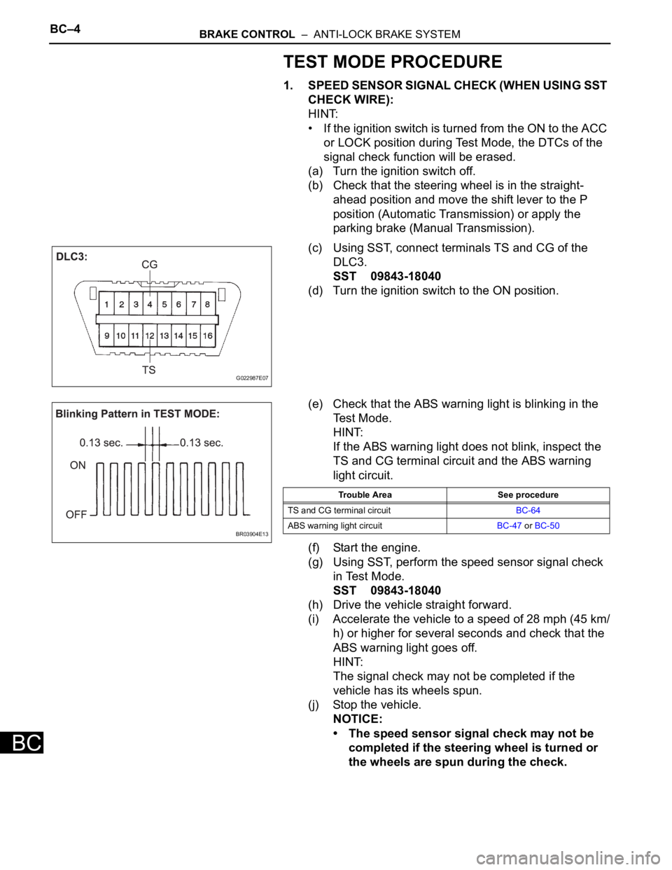
(c) Using SST, connect terminals TS and CG of the
DLC3.
SST 09843-18040
(d) Turn the ignition switch to the ON position.
(e) Check that the ABS warning light is blinking in the
Test Mode.
HINT:
If the ABS warning light does not blink, inspect the
TS and CG terminal circuit and the ABS warning
light circuit.
(f) Start the engine.
(g) Using SST, perform the speed sensor signal check
in Test Mode.
SST 09843-18040
(h) Drive the vehicle straight forward.
(i) Accelerate the vehicle to a speed of 28 mph (45 km/
h) or higher for several seconds and check that the
ABS warning light goes off.
HINT:
The signal check may not be completed if the
vehicle has its wheels spun.
(j) Stop the vehicle.
NOTICE:
• The speed sensor signal check may not be
completed if the steering wheel is turned or
the wheels are spun during the check.
G022987E07
BR03904E13
Trouble Area See procedure
TS and CG terminal circuitBC-64
ABS warning light circuitBC-47 or BC-50
Page 181 of 3000

BRAKE CONTROL – ANTI-LOCK BRAKE SYSTEMBC–5
BC
• After the ABS warning light goes off and if
vehicle speed exceeds 50 mph (80 km/h), the
signal check code will be stored again.
Decelerate or stop the vehicle before the
speed reaches 50 mph (80 km/h).
• If the signal check has not been completed,
the ABS warning light blinks while driving
and the ABS system does not operate.
HINT:
When the signal check has been completed, the
ABS warning light goes off while driving and blinks
in the Test Mode pattern while stationary.
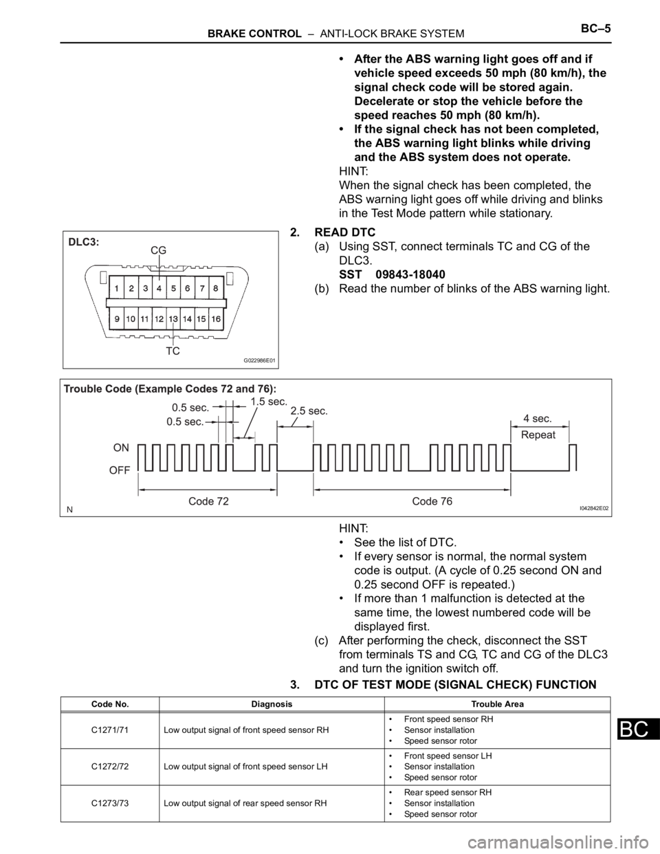
2. READ DTC
(a) Using SST, connect terminals TC and CG of the
DLC3.
SST 09843-18040
(b) Read the number of blinks of the ABS warning light.
HINT:
• See the list of DTC.
• If every sensor is normal, the normal system
code is output. (A cycle of 0.25 second ON and
0.25 second OFF is repeated.)
• If more than 1 malfunction is detected at the
same time, the lowest numbered code will be
displayed first.
(c) After performing the check, disconnect the SST
from terminals TS and CG, TC and CG of the DLC3
and turn the ignition switch off.
3. DTC OF TEST MODE (SIGNAL CHECK) FUNCTION
G022986E01
I042842E02
Code No. Diagnosis Trouble Area
C1271/71 Low output signal of front speed sensor RH• Front speed sensor RH
• Sensor installation
• Speed sensor rotor
C1272/72 Low output signal of front speed sensor LH• Front speed sensor LH
• Sensor installation
• Speed sensor rotor
C1273/73 Low output signal of rear speed sensor RH• Rear speed sensor RH
• Sensor installation
• Speed sensor rotor
Page 183 of 3000

BRAKE CONTROL – ANTI-LOCK BRAKE SYSTEMBC–7
BC
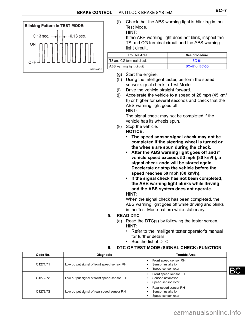
(f) Check that the ABS warning light is blinking in the
Test Mode.
HINT:
If the ABS warning light does not blink, inspect the
TS and CG terminal circuit and the ABS warning
light circuit.
(g) Start the engine.
(h) Using the intelligent tester, perform the speed
sensor signal check in Test Mode.
(i) Drive the vehicle straight forward.
(j) Accelerate the vehicle to a speed of 28 mph (45 km/
h) or higher for several seconds and check that the
ABS warning light goes off.
HINT:
The signal check may not be completed if the
vehicle has its wheels spun.
(k) Stop the vehicle.
NOTICE:
• The speed sensor signal check may not be
completed if the steering wheel is turned or
the wheels are spun during the check.
• After the ABS warning light goes off and if
vehicle speed exceeds 50 mph (80 km/h), a
signal check code will be stored again.
Decelerate or stop the vehicle before the
speed reaches 50 mph (80 km/h).
• If the signal check has not been completed,
the ABS warning light blinks while driving
and the ABS system does not operate.
HINT:
When the signal check has been completed, the
ABS warning light goes off while driving and blinks
in the Test Mode pattern while stationary.
5. READ DTC
(a) Read the DTC(s) by following the tester screen.
HINT:
• Refer to the intelligent tester operator's manual
for further details.
• See the list of DTC.
6. DTC OF TEST MODE (SIGNAL CHECK) FUNCTION
BR03904E13
Trouble Area See procedure
TS and CG terminal circuitBC-64
ABS warning light circuitBC-47 or BC-50
Code No. Diagnosis Trouble Area
C1271/71 Low output signal of front speed sensor RH• Front speed sensor RH
• Sensor installation
• Speed sensor rotor
C1272/72 Low output signal of front speed sensor LH• Front speed sensor LH
• Sensor installation
• Speed sensor rotor
C1273/73 Low output signal of rear speed sensor RH• Rear speed sensor RH
• Sensor installation
• Speed sensor rotor
Page 234 of 3000

RS–476SUPPLEMENTAL RESTRAINT SYSTEM – SIDE AIRBAG SENSOR
RS
10. PERFORM INITIALIZATION
(a) Perform initialization.
HINT:
Some systems need initialization when
disconnecting the cable from the negative battery
terminal.
11. INSPECT SRS WARNING LIGHT
(a) Inspect the SRS warning light (See page RS-27).