engine overheat TOYOTA SIENNA 2007 Service Repair Manual
[x] Cancel search | Manufacturer: TOYOTA, Model Year: 2007, Model line: SIENNA, Model: TOYOTA SIENNA 2007Pages: 3000, PDF Size: 52.26 MB
Page 61 of 3000

INTRODUCTION – HOW TO TROUBLESHOOT ECU CONTROLLED SYSTEMSIN–31
IN
ELECTRONIC CIRCUIT INSPECTION
PROCEDURE
1. BASIC INSPECTION
(a) WHEN MEASURING RESISTANCE OF
ELECTRONIC PARTS
(1) Unless otherwise stated, all resistance
measurements should be made at an ambient
temperature of 20
C (68F). Resistance
measurements may be inaccurate if measured
at high temperatures, i.e. immediately after the
vehicle has been running. Measurements should
be made after the engine has cooled down.
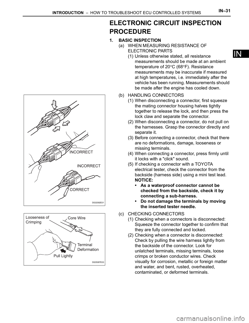
(b) HANDLING CONNECTORS
(1) When disconnecting a connector, first squeeze
the mating connector housing halves tightly
together to release the lock, and then press the
lock claw and separate the connector.
(2) When disconnecting a connector, do not pull on
the harnesses. Grasp the connector directly and
separate it.
(3) Before connecting a connector, check that there
are no deformations, damage, looseness or
missing terminals.
(4) When connecting a connector, press firmly until
it locks with a "click" sound.
(5) If checking a connector with a TOYOTA
electrical tester, check the connector from the
backside (harness side) using a mini test lead.
NOTICE:
• As a waterproof connector cannot be
checked from the backside, check it by
connecting a sub-harness.
• Do not damage the terminals by moving
the inserted tester needle.
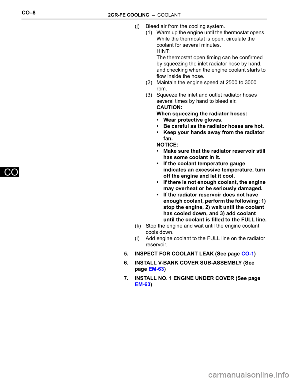
(c) CHECKING CONNECTORS
(1) Checking when a connectors is disconnected:
Squeeze the connector together to confirm that
they are fully connected and locked.
(2) Checking when a connector is disconnected:
Check by pulling the wire harness lightly from
the backside of the connector. Look for
unlatched terminals, missing terminals, loose
crimps or broken conductor wires. Check
visually for corrosion, metallic or foreign matter
and water, and bent, rusted, overheated,
contaminated, or deformed terminals.
D032092E01
D025087E03
Page 369 of 3000

2GR-FE ENGINE CONTROL SYSTEM – SFI SYSTEMES–51
ES
FAIL-SAFE CHART
If any of the following DTCs are set, the ECM enters fail-safe
mode to allow the vehicle to be driven temporarily.
HINT:
• *1: The vehicle can be driven slowly when the accelerator
pedal is depressed firmly and slowly. If the accelerator
pedal is depressed quickly, the vehicle may speed up and
slow down erratically.
• *2: Misfire related fail-safe operations occur when catalyst
overheat malfunctions occur.
DTCs Components Fail-Safe OperationsFail-Safe Deactivation
Conditions
P0031, P0032, P0051 and P0052Air-Fuel Ratio (A/F) Sensor
HeaterECM turns off A/F sensor heater Ignition switch off
P0037, P0038, P0057 and P0058Heated Oxygen (HO2) Sensor
HeaterECM turns off HO2 sensor heater Ignition switch off
P0100, P0102 and P0103 Mass Air Flow (MAF) MeterECM calculates ignition timing
according to engine speed and
throttle valve positionPass condition detected
P0110, P0112 and P0113Intake Air Temperature (IAT)
SensorECM estimates IAT to be 20
C
(68
F)Pass condition detected
P0115, P0117 and P0118Engine Coolant Temperature
(ECT) SensorECM estimates ECT to be 80
C
(176
F)Pass condition detected
P0120, P0121, P0122, P0123,
P0220, P0222, P0223, P0604,
P0606, P0607, P0657, P2102,
P2103, P2111, P2112, P2118,
P2119 and P2135Electronic Throttle Control
System (ETCS)ECM cuts off throttle actuator
current and throttle valve returned
to 6.5
throttle position by return
spring
ECM then adjusts engine output
by controlling fuel injection
(intermittent fuel-cut) and ignition
timing in accordance with
accelerator pedal opening angle,
to allow vehicle to continue at
minimal speed*1Pass condition detected and then
ignition switch turned off
P0300, P0301, P0302, P0303,
P0304, P0305 and P0306*2• Fuel injector
• Electronic Throttle Control
System (ETCS)When misfire occurs, fuel cut is
performed for catalyst overheat
malfunction prevention
• During normal load and
normal engine speed (MIL is
blinking)
- Fuel cut is performed on
malfunctioning cylinder
• During high load and high
engine speed (MIL is
blinking)
- Throttle valve opening angle
control is performed
- All cylinder fuel cut or
malfunction cylinder fuel cutPass condition detected and then
ignition switch turned OFF
P0327, P0328, P0332 and P0333 Knock SensorECM sets ignition timing to
maximum retardIgnition switch off
P0351 to P0356 Igniter ECM cuts fuel Pass condition detected
P2120, P2121, P2122, P2123,
P2125, P2127, P2128 and P2138Accelerator Pedal Position (APP)
SensorAPP sensor has 2 sensor circuits:
Main and Sub
If either of circuits malfunctions,
ECM controls engine using the
other circuit
If both of circuits malfunction,
ECM regards accelerator pedal
as being released. As a result,
throttle valve is closed and engine
idlesPass condition detected and then
ignition switch turned off
Page 1254 of 3000

CO–82GR-FE COOLING – COOLANT
CO
(j) Bleed air from the cooling system.
(1) Warm up the engine until the thermostat opens.
While the thermostat is open, circulate the
coolant for several minutes.
HINT:
The thermostat open timing can be confirmed
by squeezing the inlet radiator hose by hand,
and checking when the engine coolant starts to
flow inside the hose.
(2) Maintain the engine speed at 2500 to 3000
rpm.
(3) Squeeze the inlet and outlet radiator hoses
several times by hand to bleed air.
CAUTION:
When squeezing the radiator hoses:
• Wear protective gloves.
• Be careful as the radiator hoses are hot.
• Keep your hands away from the radiator
fan.
NOTICE:
• Make sure that the radiator reservoir still
has some coolant in it.
• If the coolant temperature gauge
indicates an excessive temperature, turn
off the engine and let it cool.
• If there is not enough coolant, the engine
may overheat or be seriously damaged.
• If the radiator reservoir does not have
enough coolant, perform the following: 1)
stop the engine, 2) wait until the coolant
has cooled down, and 3) add coolant
until the coolant is filled to the FULL line.
(k) Stop the engine and wait until the engine coolant
cools down.
(l) Add engine coolant to the FULL line on the radiator
reservoir.
5. INSPECT FOR COOLANT LEAK (See page CO-1)
6. INSTALL V-BANK COVER SUB-ASSEMBLY (See
page EM-63)
7. INSTALL NO. 1 ENGINE UNDER COVER (See page
EM-63)