heating TOYOTA SIENNA 2007 Service Repair Manual
[x] Cancel search | Manufacturer: TOYOTA, Model Year: 2007, Model line: SIENNA, Model: TOYOTA SIENNA 2007Pages: 3000, PDF Size: 52.26 MB
Page 416 of 3000

ES–1102GR-FE ENGINE CONTROL SYSTEM – SFI SYSTEM
ES
HINT:
• Bank 1 refers to the bank that includes cylinder No. 1.
• Bank 2 refers to the bank that does not include cylinder No. 1.
• Sensor 1 refers to the closest sensor to the engine assembly.
• Sensor 2 refers to the furthest sensor away from the engine assembly.
MONITOR DESCRIPTION
The ECM uses information from the Air-Fuel Ratio (A/F) sensor to regulate the air-fuel ratio and keep it
close to the stoichiometric level. This maximizes the ability of the Three-Way Catalytic Converter (TWC) to
purify the exhaust gas.
The A/F sensor detects oxygen levels in the exhaust gas and transmits the information to the ECM. The
inner surface of the sensor element is exposed to the outside air. The outer surface of the sensor element
is exposed to the exhaust gas. The sensor element is made of platinum coated zirconia and includes an
integrated heating element.
The zirconia element generates small voltage when there is a large difference in the oxygen
concentrations between the exhaust gas and outside air. The platinum coating amplifies this voltage
generation.
The A/F sensor is more efficient when heated. When the exhaust gas temperature is low, the sensor
cannot generate useful voltage signals without supplementary heating. The ECM regulates the
supplementary heating using a duty-cycle approach to adjust the average current in the sensor heater
element. If the heater current is outside the normal range, the signal transmitted by the A/F sensor will be
inaccurate, as a result, the ECM will be unable to regulate air-fuel ratio properly.
When the current in the A/F sensor heater is outside the normal operating range, the ECM interprets this
as a malfunction in the sensor heater and sets a DTC.
Example:
The ECM sets DTC P0032 or P0052 when the current in the A/F sensor heater is more than 10 A.
Conversely, when the heater current is less than 0.8 A, DTC P0031 or P0051 is set.
MONITOR STRATEGY
TYPICAL ENABLING CONDITIONS
All:
P0031 and P0051:
P0032
P0052Air-Fuel Ratio (A/F) sensor heater current more than 10
A (1 trip detection logic)• Short in A/F sensor heater circuit
• A/F sensor heater
• A/F sensor heater relay
•ECM
Related DTCsP0031: A/F sensor heater (Bank 1) range check (Low current)
P0032: A/F sensor heater (Bank 1) range check (High current)
P0051: A/F sensor heater (Bank 2) range check (Low current)
P0052: A/F sensor heater (Bank 2) range check (High current)
Required sensors / components (Main) A/F sensor heater
Required sensors / components (Related) -
Frequency of operation Continuous
Duration 10 seconds
MIL operation Immediate
Sequence operation None
The monitor will run whenever these DTCs are not
presentNone
Battery voltage 10.5 V or more
Heater ON duty ratio 50% or moreDTC No. DTC Detection Condition Trouble Area
Page 424 of 3000

ES–1182GR-FE ENGINE CONTROL SYSTEM – SFI SYSTEM
ES
HINT:
• Bank 1 refers to the bank that includes cylinder No. 1.
• Bank 2 refers to the bank that does not include cylinder No. 1.
• Sensor 1 refers to the sensor closest to the engine assembly.
• Sensor 2 refers to the sensor furthest away from the engine assembly.
MONITOR DESCRIPTION
The sensing position of the Heated Oxygen (HO2) sensor has a zirconia element which is used to detect
the oxygen concentration in the exhaust gas. If the zirconia element is at the appropriate temperature,
and the difference between the oxygen concentrations surrounding the inside and outside surfaces of the
sensor is large, the zirconia element generates voltage signals. In order to increase the oxygen
concentration detecting capacity of the zirconia element, the ECM supplements the heat from the exhaust
with heat from a heating element inside the sensor.
Heated oxygen sensor heater range check (P0037, P0038, P0057 and P0058):
The ECM monitors the current applied to the O2 sensor heater to check the heater for malfunctions. If the
current is below the threshold value, the ECM will determine that there is an open circuit in the heater. If
the current is above the threshold value, the ECM will determine that there is a short circuit in the heater.
Example:
The ECM sets DTC P0038 or P0058 when the current in the HO2 sensor heater is more than 2 A.
Conversely, when the heater current is less than 0.3 A, DTC P0037 or P0057 is set.
Heated oxygen sensor heater performance (P0141 and P0161):
After the accumulated heater ON time exceeds 100 seconds, the ECM calculates the heater resistance
using the battery voltage and the current applied to the heater. If the resistance is above the threshold
value, the ECM will determine that there is a malfunction in the HO2S heater and set DTC P0141 and
P0161.
MONITOR STRATEGY
DTC No. DTC Detection Condition Trouble Area
P0037
P0057Heated Oxygen (HO2) sensor heater current is less
than 0.3 A (1 trip detection logic)• Open in HO2 sensor heater circuit
• HO2 sensor heater
• EFI relay
•ECM
P0038
P0058Heated Oxygen (HO2) sensor heater current is more
than 2 A (1 trip detection logic)• Open in HO2 sensor heater circuit
• HO2 sensor heater
• EFI relay
•ECM
P0141
P0161Cumulative heater resistance correction value exceeds
the acceptable threshold (2 trip detection logic)• HO2 sensor
•ECM
Related DTCsP0037: Heated oxygen sensor heater (bank 1) open/short (Low electrical current)
P0038: Heated oxygen sensor heater (bank 1) open/short (High electrical current)
P0057: Heated oxygen sensor heater (bank 2) open/short (Low electrical current)
P0058: Heated oxygen sensor heater (bank 2) open/short (High electrical current)
P0141: Heated oxygen sensor heater performance (bank 1 sensor 2)
P0161: Heated oxygen sensor heater performance (bank 2 sensor 2)
Required Sensors / Components (Main) Heated oxygen sensor heater (bank 1 and 2)
Required Sensors / Components (Related) Vehicle speed sensor
Frequency of Operation Continuous
Duration0.5 seconds: P0037 and P0057
1 second: P0038 and P0058
10 seconds: P0141 and P0161
MIL OperationImmediate: P0037, P0038, P0057 and P0058
2 driving cycles: P0141 and P0161
Sequence of Operation None
Page 842 of 3000

EXTERIOR – REAR DOOR WINDOW FRAME MOULDINGET–33
ET
INSTALLATION
1. INSTALL REAR DOOR WINDOW FRAME MOULDING
(a) Remove the tape from the rear door window frame
moulding.
(b) Clean the contact surface of the vehicle body with
white gasoline.
(c) Clean the outer circumference of the rear door
window frame moulding with white gasoline.
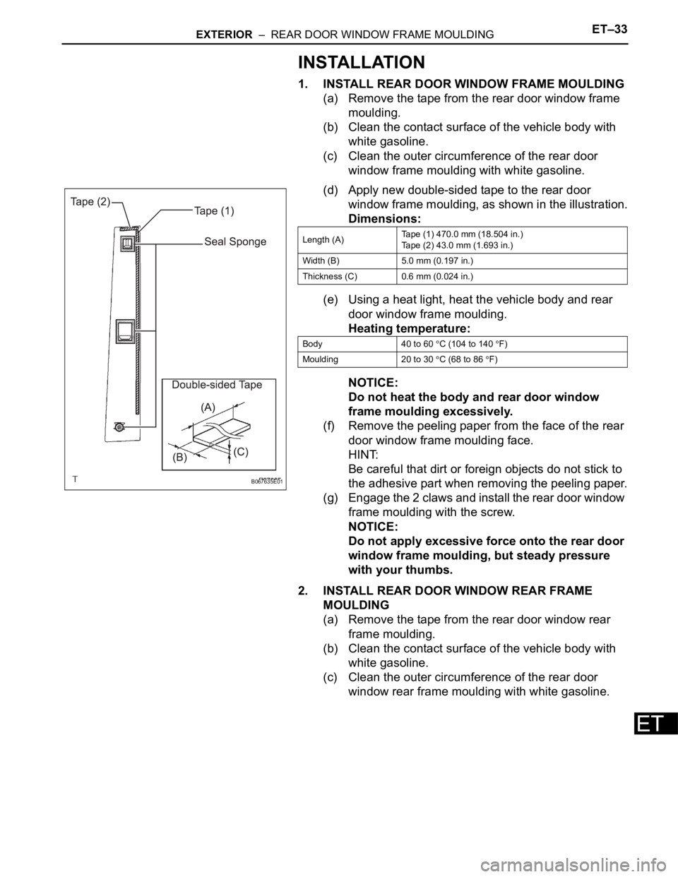
(d) Apply new double-sided tape to the rear door
window frame moulding, as shown in the illustration.
Dimensions:
(e) Using a heat light, heat the vehicle body and rear
door window frame moulding.
Heating temperature:
NOTICE:
Do not heat the body and rear door window
frame moulding excessively.
(f) Remove the peeling paper from the face of the rear
door window frame moulding face.
HINT:
Be careful that dirt or foreign objects do not stick to
the adhesive part when removing the peeling paper.
(g) Engage the 2 claws and install the rear door window
frame moulding with the screw.
NOTICE:
Do not apply excessive force onto the rear door
window frame moulding, but steady pressure
with your thumbs.
2. INSTALL REAR DOOR WINDOW REAR FRAME
MOULDING
(a) Remove the tape from the rear door window rear
frame moulding.
(b) Clean the contact surface of the vehicle body with
white gasoline.
(c) Clean the outer circumference of the rear door
window rear frame moulding with white gasoline.
B067635E01
Length (A)Tape (1) 470.0 mm (18.504 in.)
Tape (2) 43.0 mm (1.693 in.)
Width (B) 5.0 mm (0.197 in.)
Thickness (C) 0.6 mm (0.024 in.)
Body 40 to 60
C (104 to 140 F)
Moulding 20 to 30
C (68 to 86 F)
Page 843 of 3000

ET–34EXTERIOR – REAR DOOR WINDOW FRAME MOULDING
ET
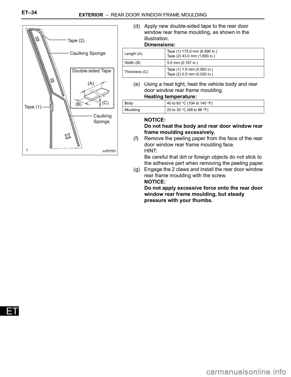
(d) Apply new double-sided tape to the rear door
window rear frame moulding, as shown in the
illustration.
Dimensions:
(e) Using a heat light, heat the vehicle body and rear
door window rear frame moulding.
Heating temperature:
NOTICE:
Do not heat the body and rear door window rear
frame moulding excessively.
(f) Remove the peeling paper from the face of the rear
door window rear frame moulding face.
HINT:
Be careful that dirt or foreign objects do not stick to
the adhesive part when removing the peeling paper.
(g) Engage the 2 claws and install the rear door window
rear frame moulding with the screw.
NOTICE:
Do not apply excessive force onto the rear door
window rear frame moulding, but steady
pressure with your thumbs.
B067637E01
Length (A)Tape (1) 175.0 mm (6.890 in.)
Tape (2) 43.0 mm (1.693 in.)
Width (B) 5.0 mm (0.197 in.)
Thickness (C)Tape (1) 1.6 mm (0.063 in.)
Tape (2) 0.5 mm (0.020 in.)
Body 40 to 60
C (104 to 140 F)
Moulding 20 to 30
C (68 to 86 F)