oil temperature TOYOTA SIENNA 2007 Service Repair Manual
[x] Cancel search | Manufacturer: TOYOTA, Model Year: 2007, Model line: SIENNA, Model: TOYOTA SIENNA 2007Pages: 3000, PDF Size: 52.26 MB
Page 16 of 3000

SS–30SERVICE SPECIFICATIONS – U151E AUTOMATIC TRANSAXLE
SS
TORQUE SPECIFICATIONS
Part Tightened N*m kgf*cm ft*lbf
Park/neutral position switch Nut 6.9 70 61 in.*lbf
Bolt 5.4 55 48 in.*lbf
Control shaft lever x Control shaft 13 130 9
Shift control cable x Control shaft lever 13 130 9
Transaxle housing x Engine block A bolt 64 653 47
B bolt 46 470 34
C bolt 43 439 32
Torque converter clutch x Drive plate 41 413 35
Flywheel housing under cover x Automatic transaxle 7.8 80 69 in.*lbf
Engine mounting bracket FR x Transaxle 64 653 47
Oil filler tube x Transaxle5.5 56 49 in.*lbf
Control cable bracket No. 1 x Transaxle 12 122 9
Control cable bracket No. 2 x Transaxle 12 122 9
Oil cooler tube clamp x Control cable bracket 5.5 56 49 in.*lbf
Oil cooler inlet tube x Transaxle27 275 20
Oil cooler outlet tube x Transaxle 27 275 20
Starter x Transaxle37 377 27
Starter wire x Starter9.8 100 87 in.*lbf
Wire harness x Transaxle13 133 10
Wire harness clamp x Transaxle8.4 86 74 in.*lbf
Speed sensor (NC) x Transaxle11 11 5 8
Speed sensor (NT) x Transaxle11 11 2 8
Air cleaner x Air cleaner hose5.0 51 44 in.*lbf
Drain plug x Oil pan49 500 36
Transmission wire x Transaxle5.4 55 48 in.*lbf
ATF temperature sensor x Valve body 6.6 67 58 in.*lbf
Oil pan x Transaxle7.8 80 69 in.*lbf
Solenoid valve x Valve body A B bolt 11 110 8
C D bolt 6.6 67 58 in.*lbf
Valve body x Transaxle11 11 0 8
Oil strainer x Valve body11 11 0 8
Floor shift assembly x Body21 214 15
Control cable x Body12 122 9
Engine mount bracket RR x Transfer stiffener plate RH 34 350 25
Oil cooler assembly x Body Nut
7.0 71 62 in.*lbf
bolt
Differential gear lube apply tube x Transaxle housing 9.8 100 87 in.*lbf
Front planetary gear lock nut
210 to 3502,141 to
3,569155 to 258
Brake apply tube clamp x Transaxle case 5.4 55 48 in.*lbf
Transaxle case No. 1 plug x Transaxle rear cover 7.4 75 65 in.*lbf
Transaxle rear cover x Transaxle case Bolt A 19 190 14
Other bolt 25 250 18
Pawl shaft clamp x Transaxle case 9.8 100 87 in.*lbf
Oil pump assembly x Transaxle case 22 226 16
Page 17 of 3000

SERVICE SPECIFICATIONS – U151E AUTOMATIC TRANSAXLESS–31
SS
Transaxle housing x Transaxle case Bolt A 22 225 16
Bolt B 29 300 22
Bolt C 29 295 21
Bolt D 22 226 16
Automatic transmission case plug x Transaxle housing 7.4 75 65 in.*lbf
Automatic transmission case plug x Transaxle case 7.4 75 65 in.*lbf
Parking lock pawl bracket x Transaxle case 20 205 15
Manual detent spring x Transaxle case Bolt A 20 205 15
Bolt B 12 120 9
Transmission wire x Transaxle housing 5.4 55 48 in.*lbf
Transmission valve body x Transaxle case 11 110 8
ATF temperature sensor clamp x Transmission valve body 6.6 67 58 in.*lbf
Valve body oil strainer assembly x Transmission valve body 11 1108
Automatic transaxle oil pan sub-assembly x Transaxle case 7.8 80 69 in.*lbf
Drain plug x Automatic transaxle oil pan sub-assembly 49 500 36
Speed sensor x Transaxle case11 11 5 8
Oil cooler tube union x Transaxle case Union 27 276 20
Elbow 27 276 20
Park/neutral start switch x nut6.9 70 61 in.*lbf
Park/neutral start switch x Bolt5.4 55 48 in.*lbf
Park/neutral start switch x Control shaft lever 13 130 9
Speedometer driven hole cover sub-assembly x Transaxle case 6.9 7061
Oil pump body x Stator shaft assembly 9.8 100 87 in.*lbf
Line pressure control solenoid assembly x Transmission valve body assembly 6.6 67 58 in.*lbf
Shift solenoid valve SL1 x Transmission valve body assembly 6.6 67 58 in.*lbf
Shift solenoid valve SL2 x Transmission valve body assembly 10.811 0 8
Shift solenoid valve SL3 x Transmission valve body assembly 6.6 67 58 in.*lbf
Shift solenoid valve S4 x Transmission valve body assembly 10.8 110 8
Shift solenoid valve DSL x Transmission valve body assembly 10.811 0 8
Front differential case x Front differential ring gear 95.1 970 70Part Tightened N*m kgf*cm ft*lbf
Page 80 of 3000
IG–62GR-FE IGNITION – IGNITION COIL AND SPARK PLUG
IG
ON-VEHICLE INSPECTION
NOTICE:
In this section, the terms "cold" and "hot" refer to the
temperature of the coils. "Cold" means approximately -
10
C (14F) to 50C (122F). "Hot" means approximately
50
C (122F) to 100C (212F).
1. INSPECT IGNITION COIL ASSEMBLY
(a) Check for DTCs.
NOTICE:
If any DTC is present, perform troubleshooting
in accordance with the procedures for that DTC.
(b) Remove the ignition coil assembly and spark plug.
(See page IG-8).
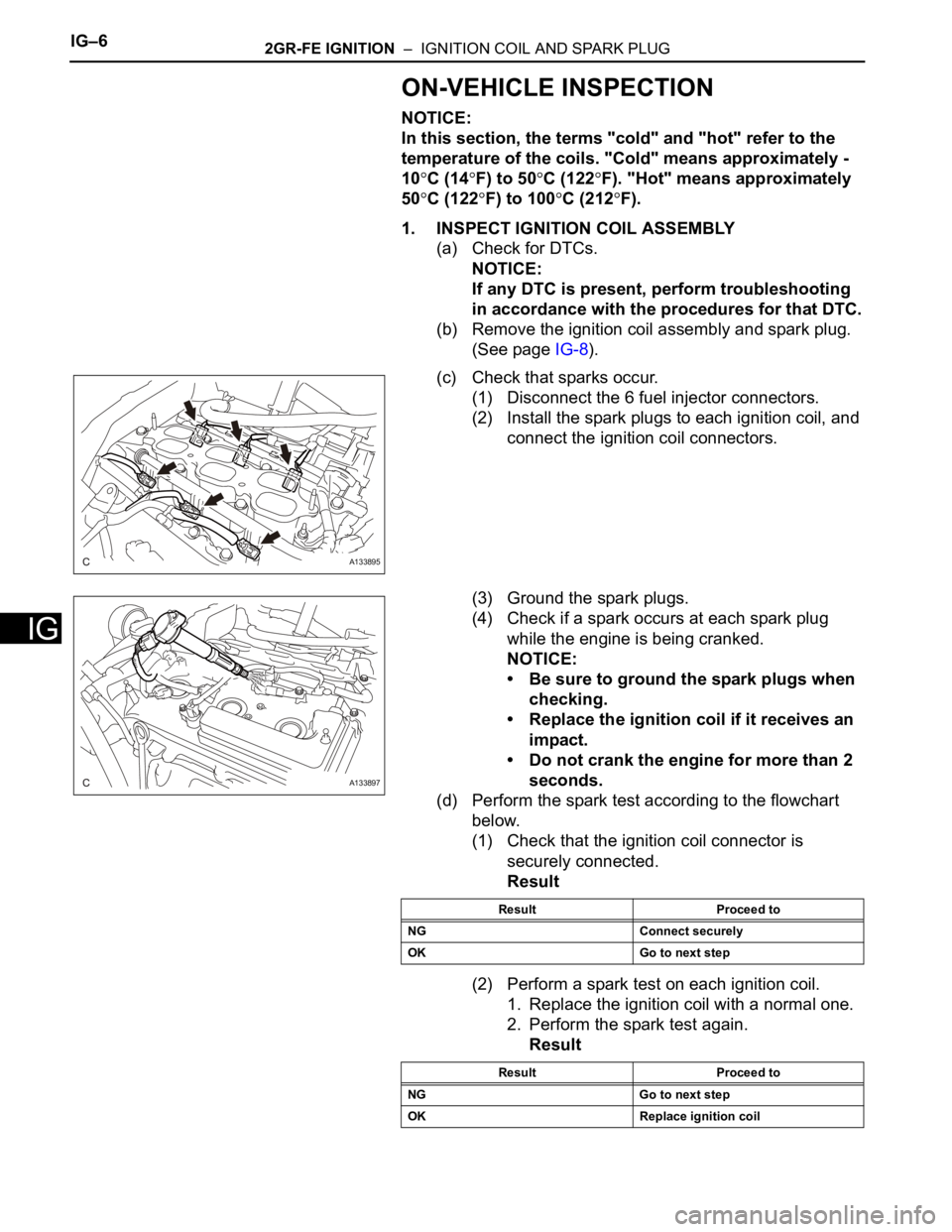
(c) Check that sparks occur.
(1) Disconnect the 6 fuel injector connectors.
(2) Install the spark plugs to each ignition coil, and
connect the ignition coil connectors.
(3) Ground the spark plugs.
(4) Check if a spark occurs at each spark plug
while the engine is being cranked.
NOTICE:
• Be sure to ground the spark plugs when
checking.
• Replace the ignition coil if it receives an
impact.
• Do not crank the engine for more than 2
seconds.
(d) Perform the spark test according to the flowchart
below.
(1) Check that the ignition coil connector is
securely connected.
Result
(2) Perform a spark test on each ignition coil.
1. Replace the ignition coil with a normal one.
2. Perform the spark test again.
Result
A133895
A133897
Result Proceed to
NG Connect securely
OK Go to next step
Result Proceed to
NG Go to next step
OK Replace ignition coil
Page 197 of 3000

SS–10SERVICE SPECIFICATIONS – 2GR-FE ENGINE MECHANICAL
SS
TORQUE SPECIFICATIONS
Part Tightened N*m kgf*cm ft.*lbf
Ignition coil assembly x Cylinder head cover sub-assembly 10 102 7
No. 1 engine hanger x Cylinder head sub-assembly RH 33 337 24
No. 2 engine hanger x Cylinder head sub-assembly LH 33 337 24
Engine mounting bracket RH x Cylinder block sub-assembly 54 551 40
No. 1 oil level gauge guide x Cylinder head sub-assembly 21 214 15
No. 2 oil level gauge guide x Cylinder block sub-assembly 21 214 15
No. 2 idler pulley sub-assembly x Timing chain cover sub-assembly 43 438 32
V-ribbed belt tensioner assembly x Cylinder block sub-assembly 43 438 32
Intake manifold x Cylinder head sub-assembly 21 214 15
Exhaust manifold sub-assembly RH x Cylinder head sub-assembly
RH21 214 15
Exhaust manifold sub-assembly LH x Cylinder head sub-assembly LH 21 214 15
Drive plate & ring gear sub-assembly x Crankshaft 83 850 61
Air cleaner case sub-assembly x Body 5.0 51 44 in.*lbf
Air cleaner case sub-assembly x Air cleaner bracket 5.0 51 44 in.*lbf
Engine coolant temperature x water by-pass joint RR 20 200 14
Engine assembly with Transaxle x Body A 85 867 63
B 32 329 24
No. 2 manifold stay x Exhaust manifold sub-assembly LH 34 347 25
No. 2 manifold stay x Cylinder block sub-assembly 34 347 25
No. 1 air cleaner inlet x Body 5.0 51 44 in.*lbf
No. 2 air cleaner inlet x Body 5.0 51 44 in.*lbf
Battery clamp x Body Bolt 5.5 56 49 in.*lbf
Nut 5.5 56 49 in.*lbf
Throttle body bracket x Intake air surge tank assembly 21 214 15
Throttle body bracket x Cylinder head cover sub-assembly RH 21 21415
No. 1 surge tank stay x Intake air surge tank assembly 21 214 15
No. 1 surge tank stay x Cylinder head cover sub-assembly RH 21 21415
No. 1 cowl top to cowl brace inner x Body 7.5 76 66 in.*lbf
No. 1 cowl top to cowl brace inner x Front outer cowl top panel sub-
assembly7.5 76 66 in.*lbf
Front outer cowl top panel sub-assembly x Body 7.5 76 66 in.*lbf
Fuel pump resistor x Front outer cowl top panel sub-assembly 7.576 66 in.*lbf
Radio setting condenser x Cylinder head cover sub-assembly RH 10102 7
Radio setting condense x Cylinder head cover sub-assembly LH 10 102 7
Intake air resonator sub-assembly x Body 5.0 51 44 in.*lbf
Air cleaner bracket x Body 7.8 80 69 in.*lbf
No. 1 vacuum switching valve assembly x Cylinder head cover sub-
assembly10 102 7
Engine mounting bracket RR x Cylinder block sub-assembly 64 650 47
Steering intermediate shaft x Steering gear 35 360 26
Stabilizer link x Shock absorber 74 755 55
Tie rod assembly x Steering gear 49 500 36
Front speed sensor x Front axle 8.0 85 71 in.*lbf
Front axle hub nut x Front drive shaft 294 2998 217
Cooler compressor assembly x V-ribbed belt tensioner 25 250 18
Cooler compressor assembly x Discharge hose sub-assembly 5.4 55 48 in.*lbf
Cooler compressor assembly x Suction hose sub-assembly 5.4 55 48 in.*lbf
Page 214 of 3000

SERVICE SPECIFICATIONS – U151F AUTOMATIC TRANSAXLESS–37
SS
TORQUE SPECIFICATIONS
Part Tightened N*m kgf*cm ft*lbf
Park/neutral position switch Nut 6.9 70 61 in.*lbf
Bolt 5.4 55 48 in.*lbf
Control shaft lever x Control shaft 13 130 9
Shift control cable x Control shaft lever 13 130 9
Transaxle housing x Engine block A bolt 64 653 47
B bolt 46 470 34
C bolt 43 439 32
Torque converter clutch x Drive plate 41 413 30
Flywheel housing under cover x Automatic transaxle 7.8 80 69 in.*lbf
Engine mounting bracket FR x Transaxle 64 653 47
Oil filler tube x Transaxle5.5 56 49 in.*lbf
Control cable bracket No. 1 x Transaxle 12 122 9
Control cable bracket No. 2 x Transaxle 12 122 9
Oil cooler tube clamp x Control cable bracket 5.5 56 49 in.*lbf
Oil cooler inlet tube x Transaxle27 275 20
Oil cooler outlet tube x Transaxle 27 275 20
Starter x Transaxle37 377 27
Starter wire x Starter9.8 100 87 in.*lbf
Wire harness x Transaxle13 133 10
Wire harness clamp x Transaxle8.4 86 74 in.*lbf
Speed sensor (NC) x Transaxle11 11 5 8
Speed sensor (NT) x Transaxle11 11 2 8
Air cleaner x Air cleaner hose5.0 51 44 in.*lbf
Drain plug x Oil pan49 500 36
Transmission wire x Transaxle5.4 55 48 in.*lbf
ATF temperature sensor x Valve body 6.6 67 58 in.*lbf
Oil pan x Transaxle7.8 80 69 in.*lbf
Solenoid valve x Valve body A B bolt 11 110 8
C D bolt 6.6 67 58 in.*lbf
Valve body x Transaxle11 11 0 8
Oil strainer x Valve body11 11 0 8
Floor shift assembly x Body21 214 15
Control cable x Body12 122 9
Transfer x Transaxle69 700 51
Transfer x Transfer stiffener plate RH 34 350 25
Engine mount bracket RR x Transfer stiffener plate RH 34 350 25
Oil cooler assembly x Body Nut
7.0 71 62 in.*lbf
bolt
Differential gear lube apply tube x Transaxle housing 9.8 100 87 in.*lbf
Front planetary gear lock nut
210 to 3502,141 to
3,569155 to 258
Brake apply tube clamp x Transaxle case 5.4 55 48 in.*lbf
Transaxle case No. 1 plug x Transaxle rear cover 7.4 75 65 in.*lbf
Transaxle rear cover x Transaxle case Bolt A 19 190 14
Other bolt 25 250 18
Pawl shaft clamp x Transaxle case 9.8 100 87 in.*lbf
Oil pump assembly x Transaxle case 22 226 16
Page 215 of 3000

SS–38SERVICE SPECIFICATIONS – U151F AUTOMATIC TRANSAXLE
SS
Transaxle housing x Transaxle case Bolt A 22 225 16
Bolt B 29 300 22
Bolt C 29 295 21
Bolt D 22 226 16
Automatic transmission case plug x Transaxle housing 7.4 75 65 in.*lbf
Automatic transmission case plug x Transaxle case 7.4 75 65 in.*lbf
Parking lock pawl bracket x Transaxle case 20 205 15
Manual detent spring x Transaxle case Bolt A 20 205 15
Bolt B 12 120 9
Transmission wire x Transaxle housing 5.4 55 48 in.*lbf
Transmission valve body x Transaxle case 11 110 8
ATF temperature sensor clamp x Transmission valve body 6.6 67 58 in.*lbf
Valve body oil strainer assembly x Transmission valve body 11 1108
Automatic transaxle oil pan sub-assembly x Transaxle case 7.8 80 69 in.*lbf
Drain plug x Automatic transaxle oil pan sub-assembly 49 500 36
Speed sensor x Transaxle case11 11 5 8
Oil cooler tube union x Transaxle case Union 27 276 20
Elbow 27 276 20
Park/neutral start switch x nut6.9 70 61 in.*lbf
Park/neutral start switch x Bolt5.4 55 48 in.*lbf
Park/neutral start switch x Control shaft lever 13 130 9
Speedometer driven hole cover sub-assembly x Transaxle case 6.9 7061
Oil pump body x Stator shaft assembly 9.8 100 87 in.*lbf
Line pressure control solenoid assembly x Transmission valve body assembly 6.6 67 58 in.*lbf
Shift solenoid valve SL1 x Transmission valve body assembly 6.6 67 58 in.*lbf
Shift solenoid valve SL2 x Transmission valve body assembly 10.811 0 8
Shift solenoid valve SL3 x Transmission valve body assembly 6.6 67 58 in.*lbf
Shift solenoid valve S4 x Transmission valve body assembly 10.8 110 8
Shift solenoid valve DSL x Transmission valve body assembly 10.811 0 8
Front differential case x Front differential ring gear 95.1 970 70Part Tightened N*m kgf*cm ft*lbf
Page 389 of 3000
2GR-FE ENGINE CONTROL SYSTEM – SFI SYSTEMES–83
ES
DESCRIPTION
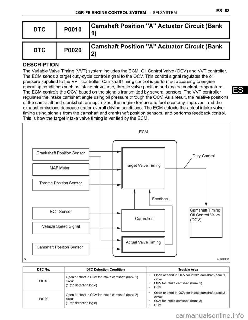
The Variable Valve Timing (VVT) system includes the ECM, Oil Control Valve (OCV) and VVT controller.
The ECM sends a target duty-cycle control signal to the OCV. This control signal regulates the oil
pressure supplied to the VVT controller. Camshaft timing control is performed according to engine
operating conditions such as intake air volume, throttle valve position and engine coolant temperature.
The ECM controls the OCV, based on the signals transmitted by several sensors. The VVT controller
regulates the intake camshaft angle using oil pressure through the OCV. As a result, the relative positions
of the camshaft and crankshaft are optimized, the engine torque and fuel economy improves, and the
exhaust emissions decrease under overall driving conditions. The ECM detects the actual intake valve
timing using signals from the camshaft and crankshaft position sensors, and performs feedback control.
This is how the target intake valve timing is verified by the ECM.
DTC P0010Camshaft Position "A" Actuator Circuit (Bank
1)
DTC P0020Camshaft Position "A" Actuator Circuit (Bank
2)
DTC No. DTC Detection Condition Trouble Area
P0010Open or short in OCV for intake camshaft (bank 1)
circuit
(1 trip detection logic)• Open or short in OCV for intake camshaft (bank 1)
circuit
• OCV for intake camshaft (bank 1)
•ECM
P0020Open or short in OCV for intake camshaft (bank 2)
circuit
(1 trip detection logic)• Open or short in OCV for intake camshaft (bank 2)
circuit
• OCV for intake camshaft (bank 2)
•ECM
A103843E02
Page 401 of 3000
2GR-FE ENGINE CONTROL SYSTEM – SFI SYSTEMES–95
ES
DESCRIPTION
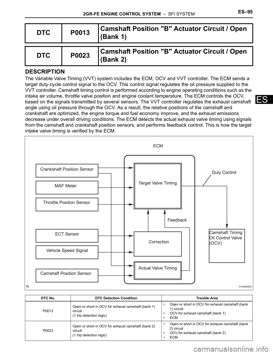
The Variable Valve Timing (VVT) system includes the ECM, OCV and VVT controller. The ECM sends a
target duty-cycle control signal to the OCV. This control signal regulates the oil pressure supplied to the
VVT controller. Camshaft timing control is performed according to engine operating conditions such as the
intake air volume, throttle valve position and engine coolant temperature. The ECM controls the OCV,
based on the signals transmitted by several sensors. The VVT controller regulates the exhaust camshaft
angle using oil pressure through the OCV. As a result, the relative positions of the camshaft and
crankshaft are optimized, the engine torque and fuel economy improve, and the exhaust emissions
decrease under overall driving conditions. The ECM detects the actual exhaust valve timing using signals
from the camshaft and crankshaft position sensors, and performs feedback control. This is how the target
intake valve timing is verified by the ECM.
DTC P0013Camshaft Position "B" Actuator Circuit / Open
(Bank 1)
DTC P0023Camshaft Position "B" Actuator Circuit / Open
(Bank 2)
DTC No. DTC Detection Condition Trouble Area
P0013Open or short in OCV for exhaust camshaft (bank 1)
circuit
(1 trip detection logic)• Open or short in OCV for exhaust camshaft (bank
1) circuit
• OCV for exhaust camshaft (bank 1)
•ECM
P0023Open or short in OCV for exhaust camshaft (bank 2)
circuit
(1 trip detection logic)• Open or short in OCV for exhaust camshaft (bank
2) circuit
• OCV for exhaust camshaft (bank 2)
•ECM
A103843E02
Page 511 of 3000

2GR-FE ENGINE CONTROL SYSTEM – SFI SYSTEMES–205
ES
When multiple DTCs for misfiring cylinders are set, but DTC P0300 is not set, it indicates that misfires
have been detected in different cylinders at different times. DTC P0300 is only set when several misfiring
cylinders are detected at the same time.
MONITOR DESCRIPTION
The ECM illuminates the MIL and sets a DTC when either one of the following conditions, which could
cause emission deterioration, is detected (2 trip detection logic).
• Within the first 1000 crankshaft revolutions of the engine starting, an excessive misfiring rate
(approximately 20 to 50 misfires per 1000 crankshaft revolutions) occurs once.
• An excessive misfiring rate (approximately 20 to 50 misfires per 1,000 crankshaft revolutions) occurs a
total of 4 times.
The ECM flashes the MIL and sets a DTC when either one of the following conditions, which could cause
the Three-Way Catalytic Converter (TWC) damage, is detected (2 trip detection logic).
• At a high engine rpm, a catalyst damage misfire, which monitored every 200 crankshaft revolutions,
occurs once.
• At a normal engine rpm, a catalyst damage misfire, which monitored every 200 crankshaft revolutions,
occurs 3 times.
HINT:
If a catalyst damage misfire occurs, the ECM informs the driver by flashing the MIL.
MONITOR STRATEGY
TYPICAL ENABLING CONDITIONS
Misfire:
Monitor period of emission-related-misfire:
Related DTCsP0300: Multiple cylinder misfire
P0301: Cylinder 1 misfire
P0302: Cylinder 2 misfire
P0303: Cylinder 3 misfire
P0304: Cylinder 4 misfire
P0305: Cylinder 5 misfire
P0306: Cylinder 6 misfire
Required Sensors / Components (Main) Injector, Ignition coil, Spark plug
Required Sensors / Components (Related)Crankshaft, Camshaft, Engine coolant temperature and intake air temperature
sensors and Mass air flow meter
Frequency of Operation Continuous
Duration1000 to 4000 crankshaft revolutions: Emission related misfire
200 to 600 crankshaft revolutions: Catalyst damaged misfire
MIL Operation2 driving cycles: Emission related misfire
MIL flashes immediately: Catalyst damaged misfire
Sequence of Operation None
The monitor will run whenever these DTCs are not
presentP0100, P0101, P0102, P0103 (MAF Sensor), P0110, P0112, P0113 (IAT Sensor),
P0115, P0116, P0117, P0118 (ECT Sensor), P0120, P0121, P0122, P0123, P0220,
P0222, P0223, P2135 (TP Sensor), P0125 (Insufficient ECT for Closed Loop),
P0327, P0328, P0332, P0333 (Knock Sensor), P0335 (CKP Sensor), P0340, (CMP
Sensor), P0500 (VSS)
Battery voltage 8 V or more
VVT system No operate by scan tool
Engine RPM 450 to 6500 rpm
Either of the following conditions is met Condition (a) or (b)
(a) Engine start ECT More than -7
C (19F)
(b) ECT More than 20
C (68F)
Fuel-cut OFF
First 1000 revolutions after engine start, or check mode Crankshaft 1000 revolutions
Page 537 of 3000
2GR-FE ENGINE CONTROL SYSTEM – SFI SYSTEMES–231
ES
INSPECTION PROCEDURE
HINT:
• If no problem is found by this diagnostic troubleshooting procedure, troubleshoot the engine
mechanical systems.
• Check the engine speed. The engine speed can be checked by using the intelligent tester. Perform the
following procedure:
(a) Connect the intelligent tester to the DLC3.
(b) Start the engine.
(c) Turn the tester on.
(d) Select the following menu items: DIAGNOSIS / ENHANCED OBD II / DATA LIST / PRIMARY /
ENGINE SPD.
The engine speed may be indicated as zero despite the engine revolving normally. This is caused
by a lack of NE signals from the Crankshaft Position (CKP) sensor. Alternatively, the engine speed
may be indicated as lower than the actual engine speed, if the CKP sensor voltage output is
insufficient.
• Read freeze frame data using the intelligent tester. The ECM records vehicle and driving condition
information as freeze frame data the moment a DTC is stored. When troubleshooting, freeze frame
data can be helpful in determining whether the vehicle was running or stopped, whether the engine
was warmed up or not, whether the air-fuel ratio was lean or rich, as well as other data recorded at the
time of a malfunction.
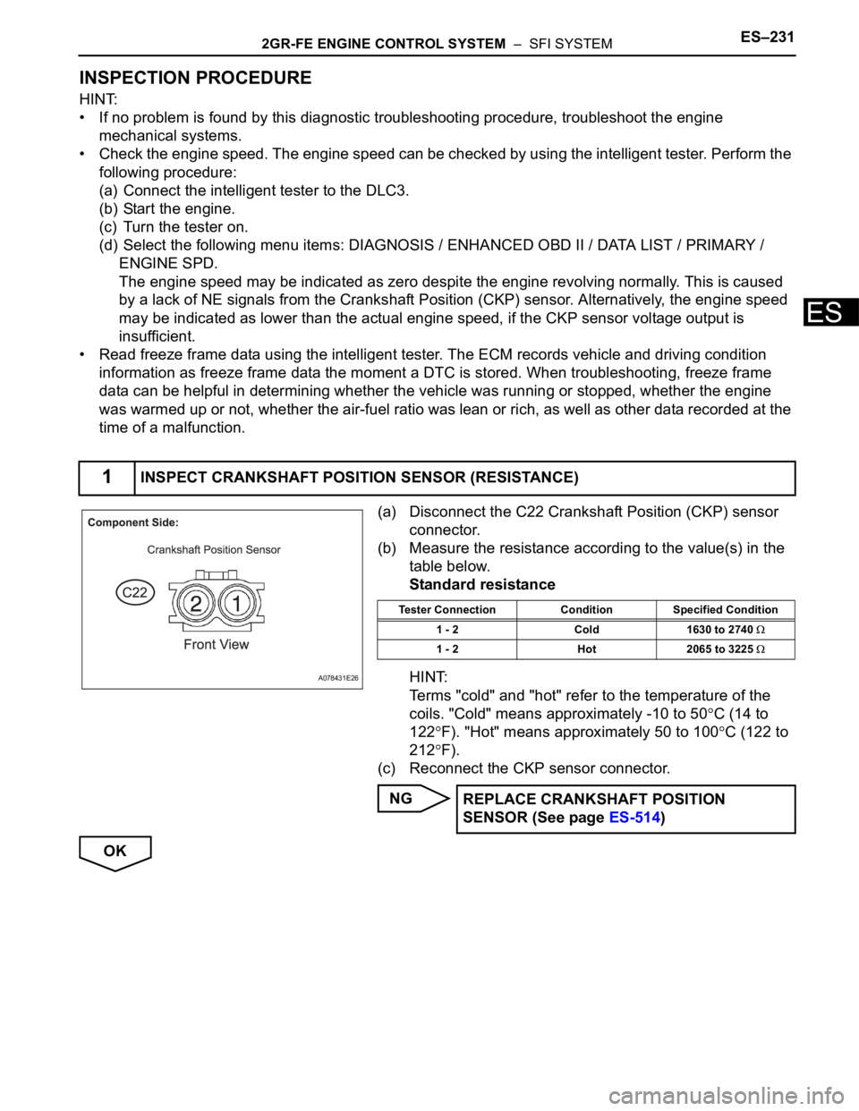
(a) Disconnect the C22 Crankshaft Position (CKP) sensor
connector.
(b) Measure the resistance according to the value(s) in the
table below.
Standard resistance
HINT:
Terms "cold" and "hot" refer to the temperature of the
coils. "Cold" means approximately -10 to 50
C (14 to
122
F). "Hot" means approximately 50 to 100C (122 to
212
F).
(c) Reconnect the CKP sensor connector.
NG
OK
1INSPECT CRANKSHAFT POSITION SENSOR (RESISTANCE)
A078431E26
Tester Connection Condition Specified Condition
1 - 2 Cold 1630 to 2740
1 - 2 Hot 2065 to 3225
REPLACE CRANKSHAFT POSITION
SENSOR (See page ES-514)