oil temperature TOYOTA SIENNA 2007 Service Owner's Manual
[x] Cancel search | Manufacturer: TOYOTA, Model Year: 2007, Model line: SIENNA, Model: TOYOTA SIENNA 2007Pages: 3000, PDF Size: 52.26 MB
Page 1499 of 3000
U151E AUTOMATIC TRANSAXLE – AUTOMATIC TRANSAXLE FLUIDAX–123
AX
AUTOMATIC TRANSAXLE FLUID
ON-VEHICLE INSPECTION
1. CHECK FLUID LEVEL
HINT:
Drive the vehicle so that the engine and transaxle are at
normal operating temperature.
Fluid temperature:
70 to 80
C (158 to 176F)
(a) Park the vehicle on a level surface and set the
parking brake.
(b) With the engine idling and the brake pedal
depressed, move the shift lever to all positions from
P to L and return to the P position.
(c) Take out the dipstick and wipe it clean.
(d) Put the dipstick back all the way.
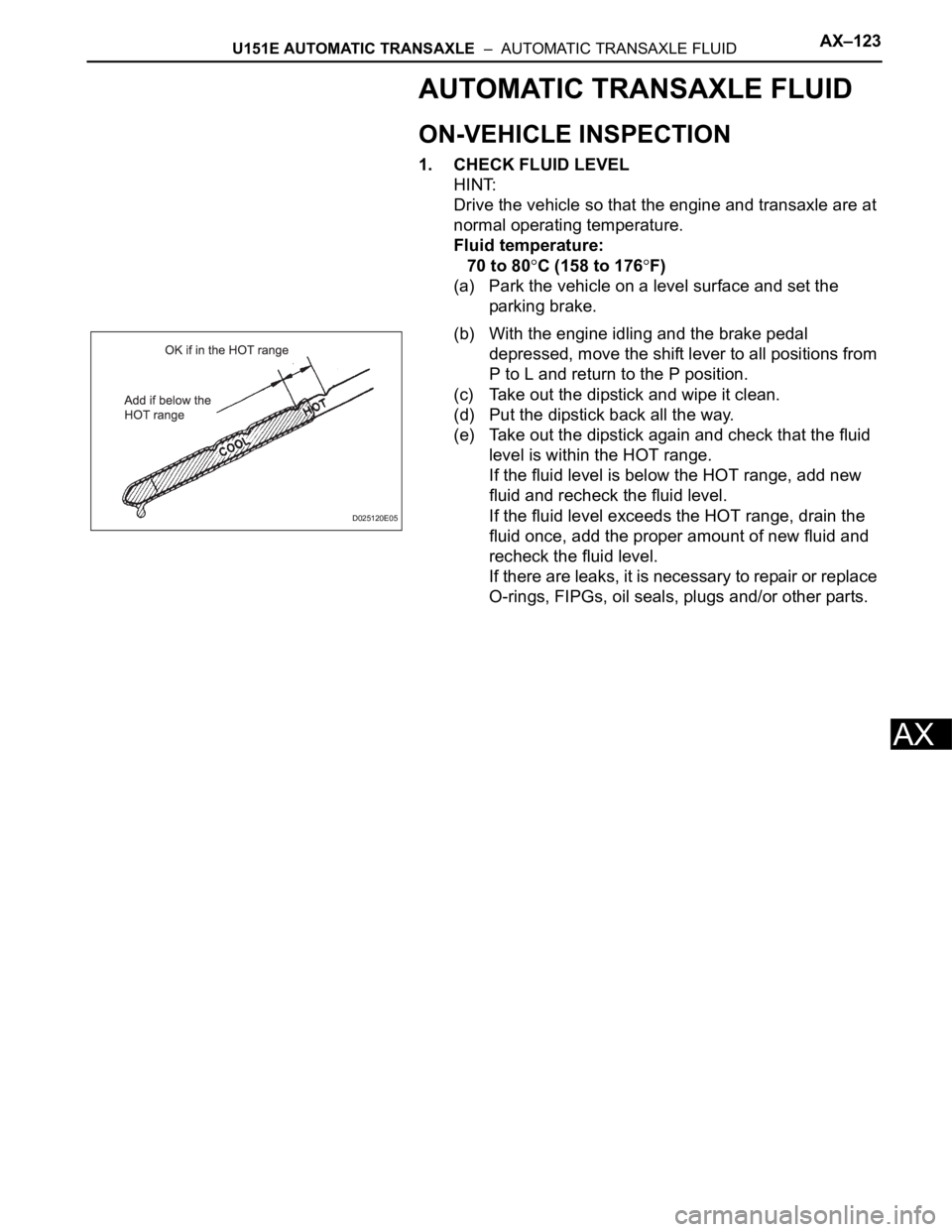
(e) Take out the dipstick again and check that the fluid
level is within the HOT range.
If the fluid level is below the HOT range, add new
fluid and recheck the fluid level.
If the fluid level exceeds the HOT range, drain the
fluid once, add the proper amount of new fluid and
recheck the fluid level.
If there are leaks, it is necessary to repair or replace
O-rings, FIPGs, oil seals, plugs and/or other parts.
D025120E05
Page 1514 of 3000
U151E AUTOMATIC TRANSAXLE – TRANSMISSION WIREAX–131
AX
REMOVAL
1. DISCONNECT CABLE FROM NEGATIVE BATTERY
TERMINAL
2. REMOVE ENGINE UNDER COVER NO.1
3. DRAIN AUTOMATIC TRANSAXLE FLUID
(a) Remove the drain plug and gasket, and drain the
AT F.
(b) Install a new gasket and the drain plug.
Torque: 49 N*m (500 kgf*cm, 36 ft.*lbf)
4. REMOVE AUTOMATIC TRANSAXLE OIL PAN SUB-
ASSEMBLY
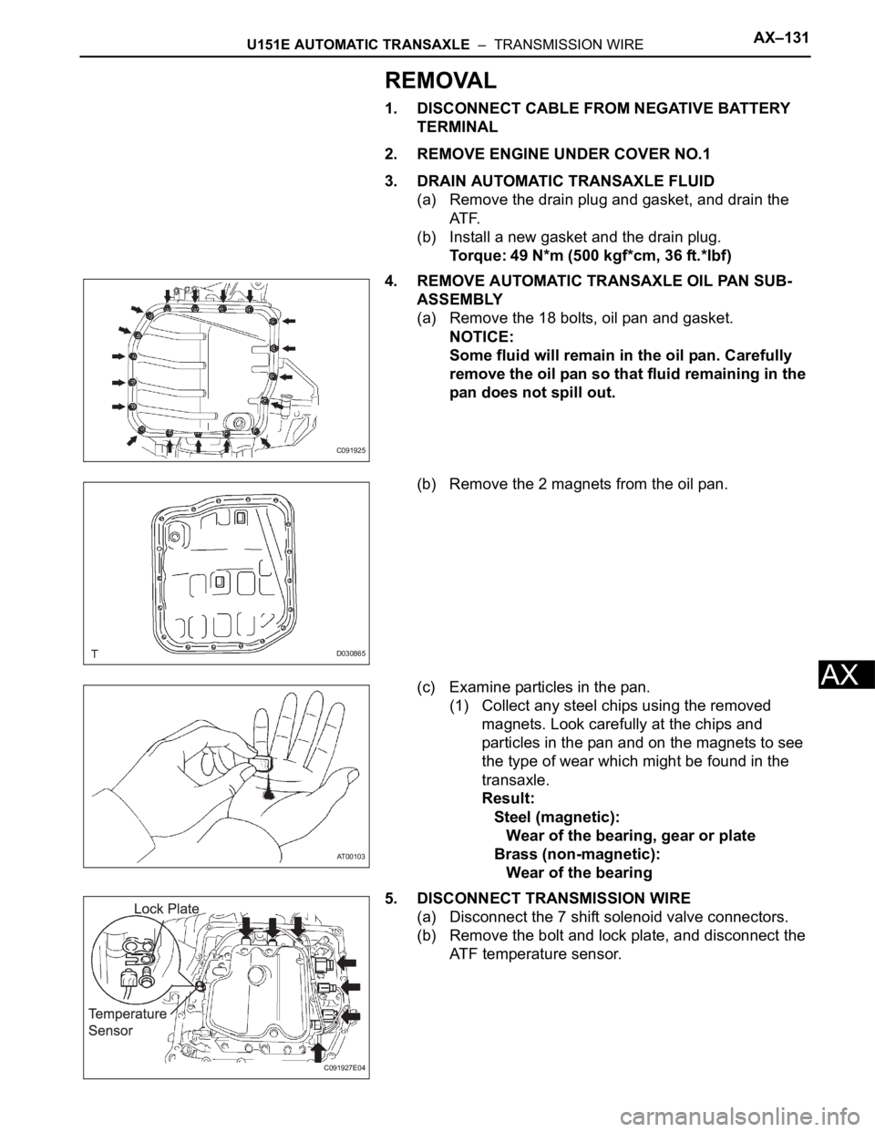
(a) Remove the 18 bolts, oil pan and gasket.
NOTICE:
Some fluid will remain in the oil pan. Carefully
remove the oil pan so that fluid remaining in the
pan does not spill out.
(b) Remove the 2 magnets from the oil pan.
(c) Examine particles in the pan.
(1) Collect any steel chips using the removed
magnets. Look carefully at the chips and
particles in the pan and on the magnets to see
the type of wear which might be found in the
transaxle.
Result:
Steel (magnetic):
Wear of the bearing, gear or plate
Brass (non-magnetic):
Wear of the bearing
5. DISCONNECT TRANSMISSION WIRE
(a) Disconnect the 7 shift solenoid valve connectors.
(b) Remove the bolt and lock plate, and disconnect the
ATF temperature sensor.
C091925
D030865
AT00103
C091927E04
Page 1515 of 3000
AX–132U151E AUTOMATIC TRANSAXLE – TRANSMISSION WIRE
AX
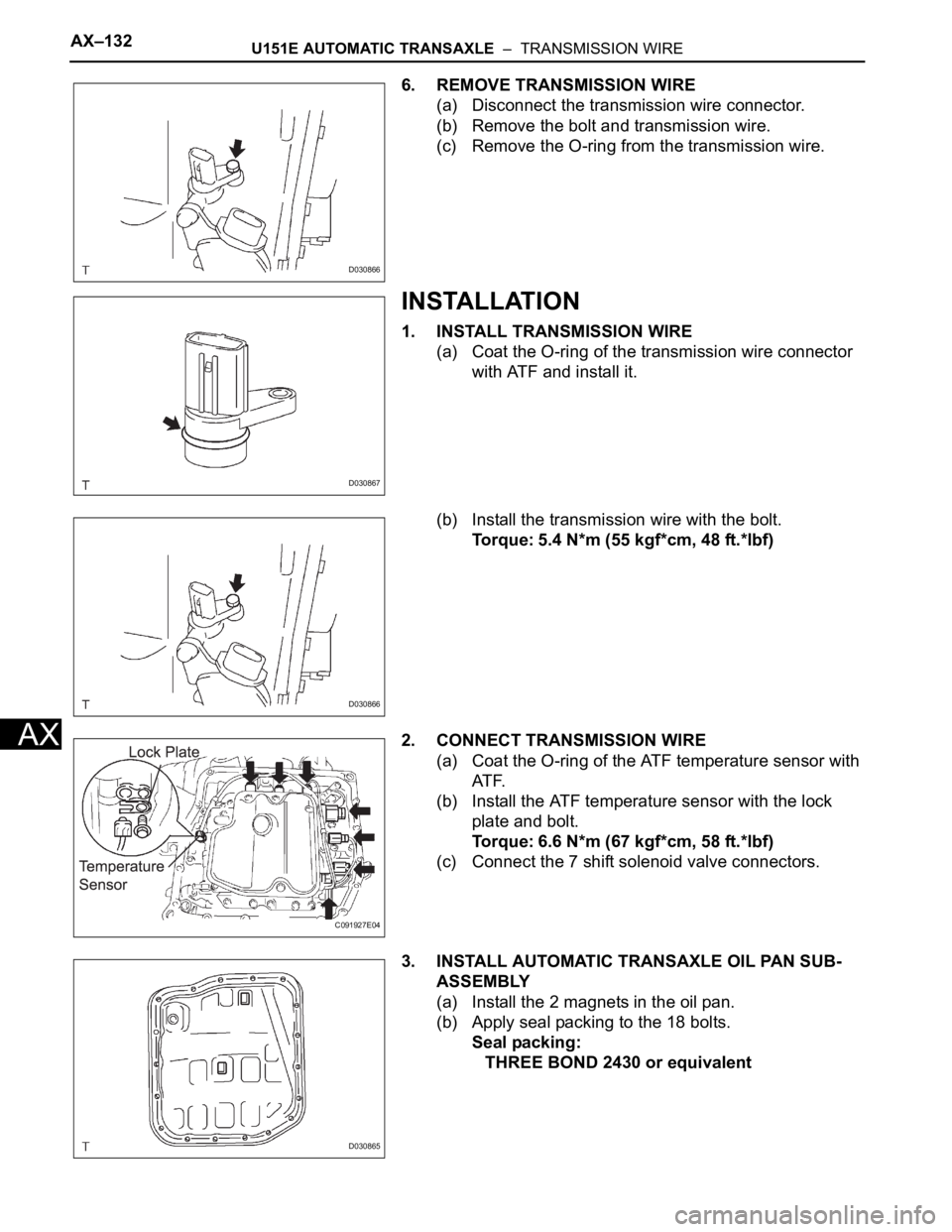
6. REMOVE TRANSMISSION WIRE
(a) Disconnect the transmission wire connector.
(b) Remove the bolt and transmission wire.
(c) Remove the O-ring from the transmission wire.
INSTALLATION
1. INSTALL TRANSMISSION WIRE
(a) Coat the O-ring of the transmission wire connector
with ATF and install it.
(b) Install the transmission wire with the bolt.
Torque: 5.4 N*m (55 kgf*cm, 48 ft.*lbf)
2. CONNECT TRANSMISSION WIRE
(a) Coat the O-ring of the ATF temperature sensor with
AT F.
(b) Install the ATF temperature sensor with the lock
plate and bolt.
Torque: 6.6 N*m (67 kgf*cm, 58 ft.*lbf)
(c) Connect the 7 shift solenoid valve connectors.
3. INSTALL AUTOMATIC TRANSAXLE OIL PAN SUB-
ASSEMBLY
(a) Install the 2 magnets in the oil pan.
(b) Apply seal packing to the 18 bolts.
Seal packing:
THREE BOND 2430 or equivalent
D030866
D030867
D030866
C091927E04
D030865
Page 1519 of 3000
AX–136U151E AUTOMATIC TRANSAXLE – VALVE BODY ASSEMBLY
AX
REMOVAL
1. REMOVE ENGINE UNDER COVER NO.1
2. DISCONNECT CABLE FROM NEGATIVE BATTERY
TERMINAL
3. DRAIN AUTOMATIC TRANSAXLE FLUID (See page
AX-131)
4. REMOVE AUTOMATIC TRANSAXLE OIL PAN SUB-
ASSEMBLY
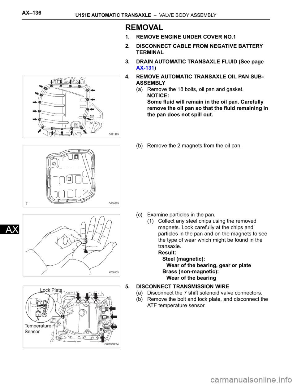
(a) Remove the 18 bolts, oil pan and gasket.
NOTICE:
Some fluid will remain in the oil pan. Carefully
remove the oil pan so that the fluid remaining in
the pan does not spill out.
(b) Remove the 2 magnets from the oil pan.
(c) Examine particles in the pan.
(1) Collect any steel chips using the removed
magnets. Look carefully at the chips and
particles in the pan and on the magnets to see
the type of wear which might be found in the
transaxle.
Result:
Steel (magnetic):
Wear of the bearing, gear or plate
Brass (non-magnetic):
Wear of the bearing
5. DISCONNECT TRANSMISSION WIRE
(a) Disconnect the 7 shift solenoid valve connectors.
(b) Remove the bolt and lock plate, and disconnect the
ATF temperature sensor.
C091925
D030865
AT00103
C091927E04
Page 1524 of 3000
U151E AUTOMATIC TRANSAXLE – VALVE BODY ASSEMBLYAX–141
AX
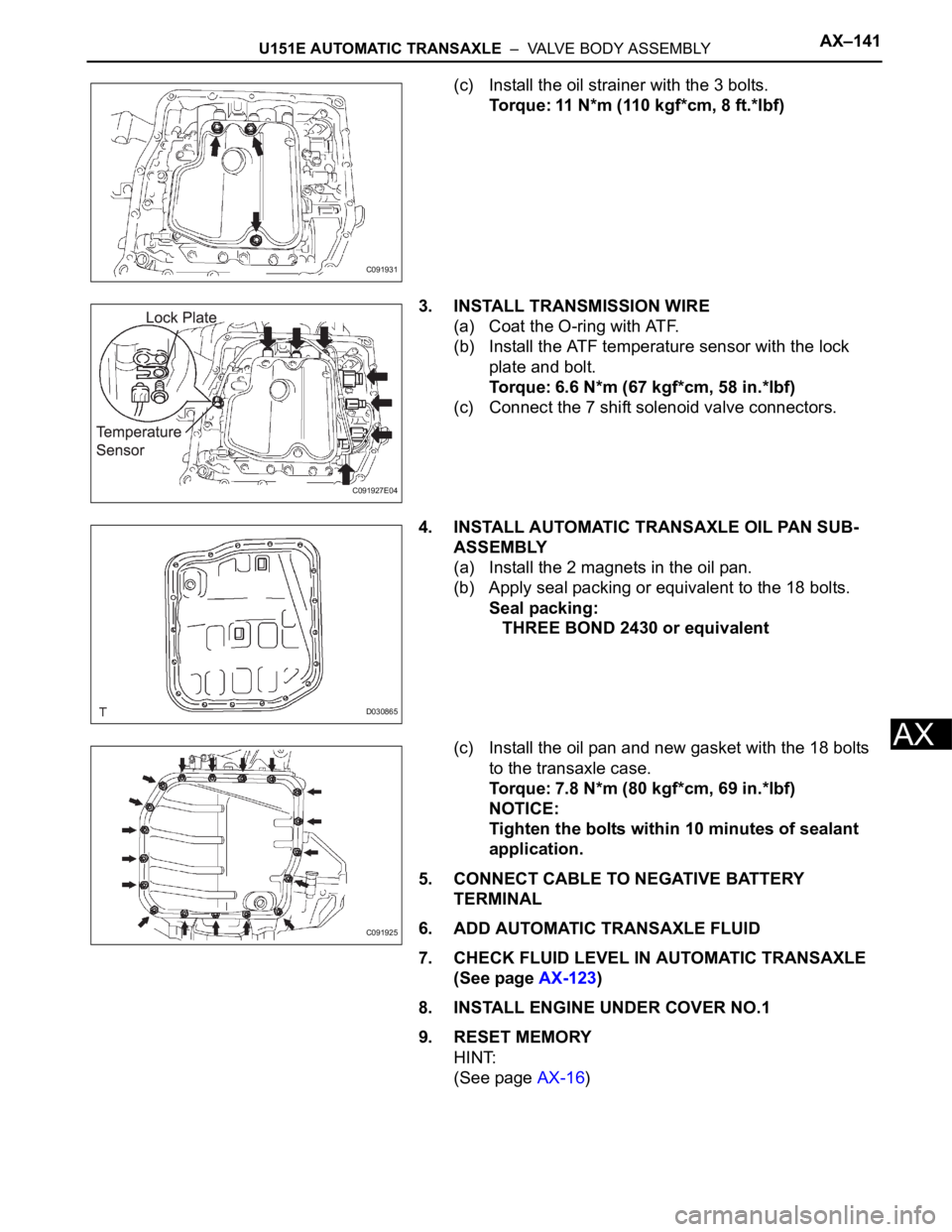
(c) Install the oil strainer with the 3 bolts.
Torque: 11 N*m (110 kgf*cm, 8 ft.*lbf)
3. INSTALL TRANSMISSION WIRE
(a) Coat the O-ring with ATF.
(b) Install the ATF temperature sensor with the lock
plate and bolt.
Torque: 6.6 N*m (67 kgf*cm, 58 in.*lbf)
(c) Connect the 7 shift solenoid valve connectors.
4. INSTALL AUTOMATIC TRANSAXLE OIL PAN SUB-
ASSEMBLY
(a) Install the 2 magnets in the oil pan.
(b) Apply seal packing or equivalent to the 18 bolts.
Seal packing:
THREE BOND 2430 or equivalent
(c) Install the oil pan and new gasket with the 18 bolts
to the transaxle case.
Torque: 7.8 N*m (80 kgf*cm, 69 in.*lbf)
NOTICE:
Tighten the bolts within 10 minutes of sealant
application.
5. CONNECT CABLE TO NEGATIVE BATTERY
TERMINAL
6. ADD AUTOMATIC TRANSAXLE FLUID
7. CHECK FLUID LEVEL IN AUTOMATIC TRANSAXLE
(See page AX-123)
8. INSTALL ENGINE UNDER COVER NO.1
9. RESET MEMORY
HINT:
(See page AX-16)
C091931
C091927E04
D030865
C091925
Page 1558 of 3000
U151E AUTOMATIC TRANSAXLE – AUTOMATIC TRANSAXLE UNITAX–179
AX
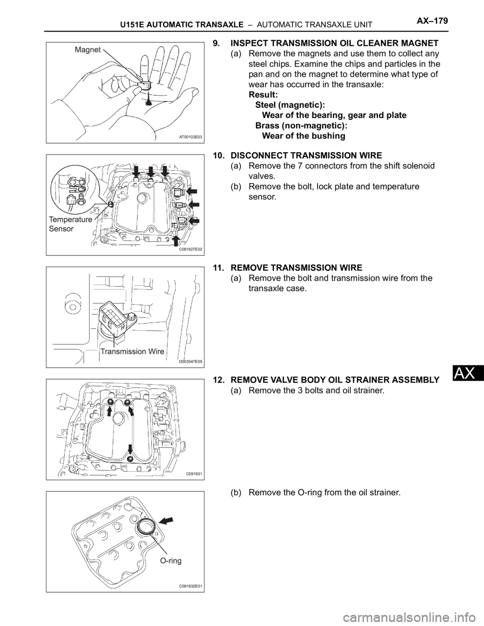
9. INSPECT TRANSMISSION OIL CLEANER MAGNET
(a) Remove the magnets and use them to collect any
steel chips. Examine the chips and particles in the
pan and on the magnet to determine what type of
wear has occurred in the transaxle:
Result:
Steel (magnetic):
Wear of the bearing, gear and plate
Brass (non-magnetic):
Wear of the bushing
10. DISCONNECT TRANSMISSION WIRE
(a) Remove the 7 connectors from the shift solenoid
valves.
(b) Remove the bolt, lock plate and temperature
sensor.
11. REMOVE TRANSMISSION WIRE
(a) Remove the bolt and transmission wire from the
transaxle case.
12. REMOVE VALVE BODY OIL STRAINER ASSEMBLY
(a) Remove the 3 bolts and oil strainer.
(b) Remove the O-ring from the oil strainer.
AT00103E03
C091927E02
D003547E05
C091931
C091932E01
Page 1623 of 3000
U151E AUTOMATIC TRANSAXLE – AUTOMATIC TRANSAXLE UNITAX–179
AX
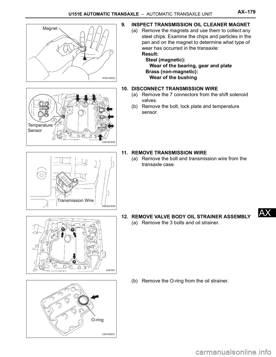
9. INSPECT TRANSMISSION OIL CLEANER MAGNET
(a) Remove the magnets and use them to collect any
steel chips. Examine the chips and particles in the
pan and on the magnet to determine what type of
wear has occurred in the transaxle:
Result:
Steel (magnetic):
Wear of the bearing, gear and plate
Brass (non-magnetic):
Wear of the bushing
10. DISCONNECT TRANSMISSION WIRE
(a) Remove the 7 connectors from the shift solenoid
valves.
(b) Remove the bolt, lock plate and temperature
sensor.
11. REMOVE TRANSMISSION WIRE
(a) Remove the bolt and transmission wire from the
transaxle case.
12. REMOVE VALVE BODY OIL STRAINER ASSEMBLY
(a) Remove the 3 bolts and oil strainer.
(b) Remove the O-ring from the oil strainer.
AT00103E03
C091927E02
D003547E05
C091931
C091932E01
Page 1724 of 3000
AX–52U151F AUTOMATIC TRANSAXLE – AUTOMATIC TRANSAXLE SYSTEM
AX
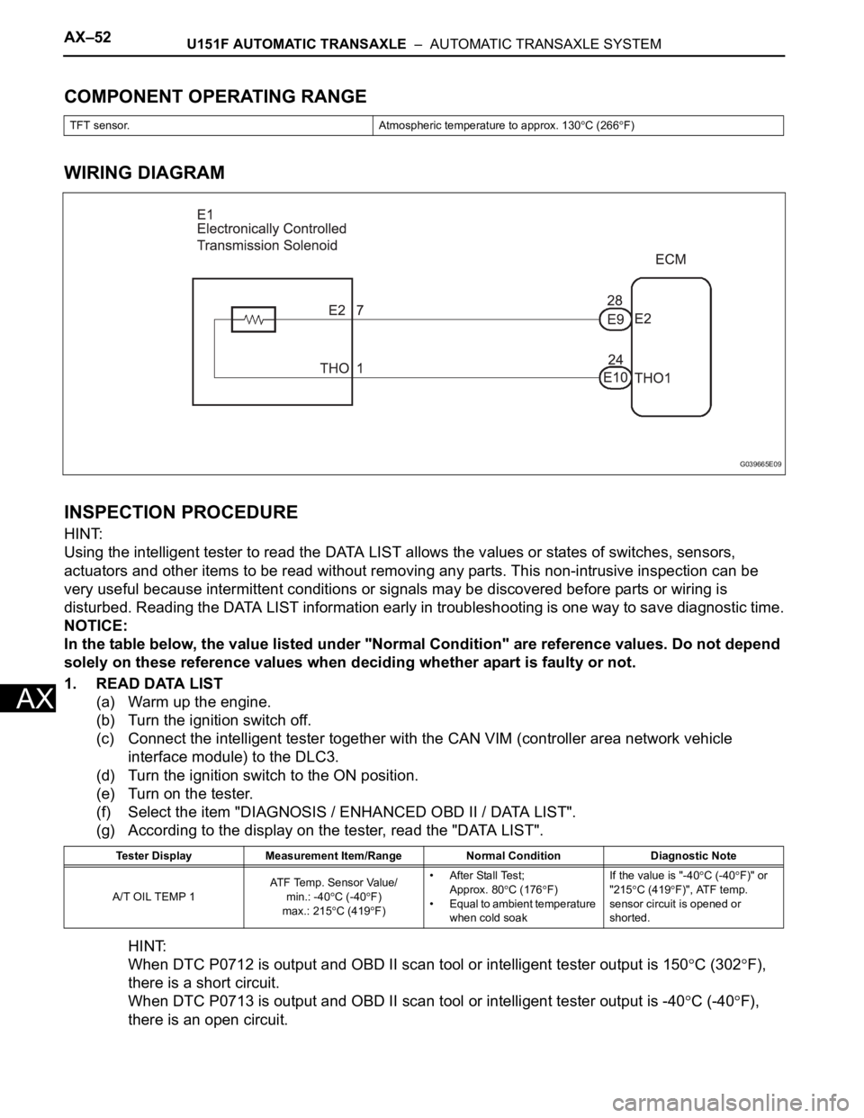
COMPONENT OPERATING RANGE
WIRING DIAGRAM
INSPECTION PROCEDURE
HINT:
Using the intelligent tester to read the DATA LIST allows the values or states of switches, sensors,
actuators and other items to be read without removing any parts. This non-intrusive inspection can be
very useful because intermittent conditions or signals may be discovered before parts or wiring is
disturbed. Reading the DATA LIST information early in troubleshooting is one way to save diagnostic time.
NOTICE:
In the table below, the value listed under "Normal Condition" are reference values. Do not depend
solely on these reference values when deciding whether apart is faulty or not.
1. READ DATA LIST
(a) Warm up the engine.
(b) Turn the ignition switch off.
(c) Connect the intelligent tester together with the CAN VIM (controller area network vehicle
interface module) to the DLC3.
(d) Turn the ignition switch to the ON position.
(e) Turn on the tester.
(f) Select the item "DIAGNOSIS / ENHANCED OBD II / DATA LIST".
(g) According to the display on the tester, read the "DATA LIST".
HINT:
When DTC P0712 is output and OBD II scan tool or intelligent tester output is 150
C (302F),
there is a short circuit.
When DTC P0713 is output and OBD II scan tool or intelligent tester output is -40
C (-40F),
there is an open circuit.
TFT sensor. Atmospheric temperature to approx. 130C (266F)
Tester Display Measurement Item/Range Normal Condition Diagnostic Note
A/T OIL TEMP 1AT F Te m p . S e n s o r Va l u e /
min.: -40
C (-40F)
max.: 215
C (419F)• After Stall Test;
Approx. 80
C (176F)
• Equal to ambient temperature
when cold soakIf the value is "-40
C (-40F)" or
"215
C (419F)", ATF temp.
sensor circuit is opened or
shorted.
G039665E09
Page 1729 of 3000
U151F AUTOMATIC TRANSAXLE – AUTOMATIC TRANSAXLE SYSTEMAX–57
AX
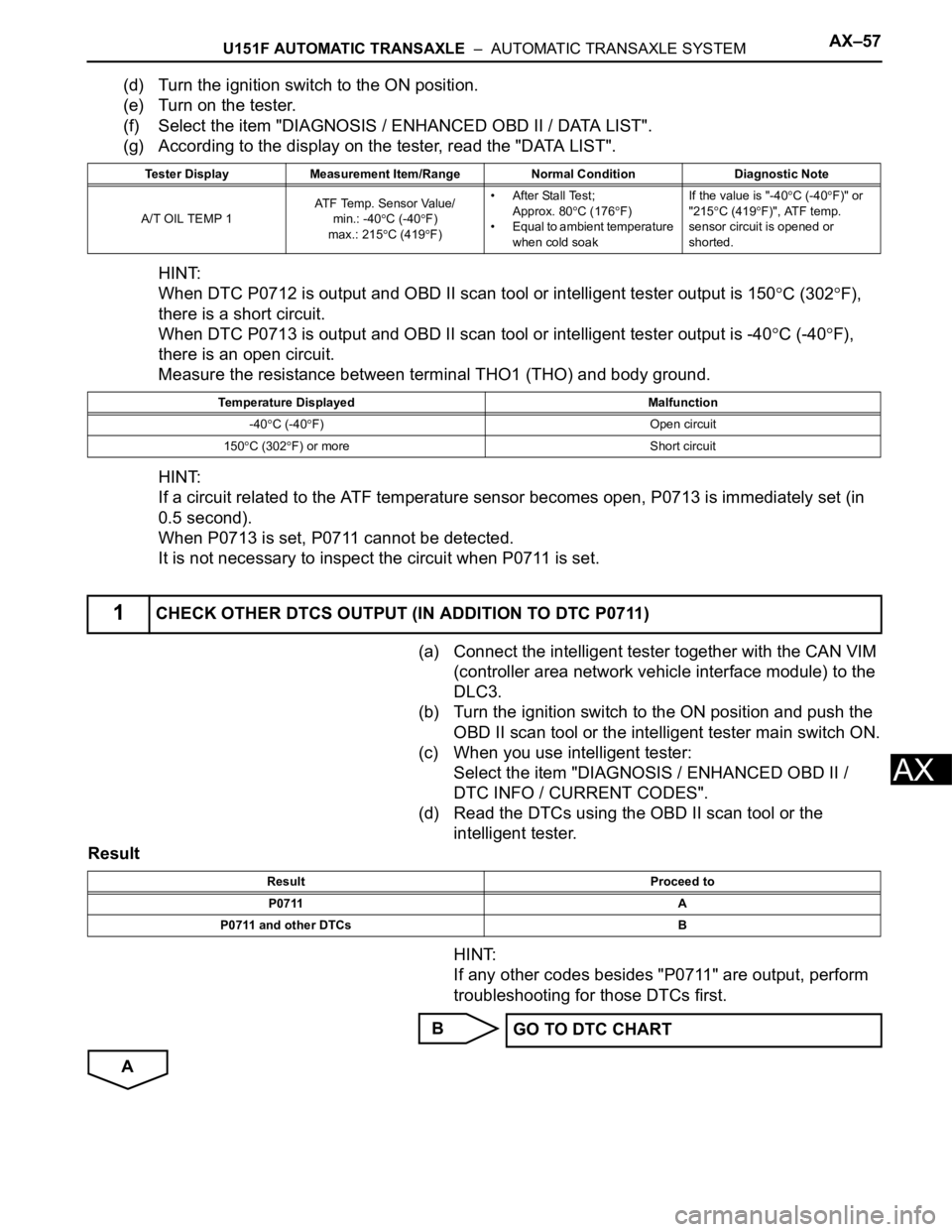
(d) Turn the ignition switch to the ON position.
(e) Turn on the tester.
(f) Select the item "DIAGNOSIS / ENHANCED OBD II / DATA LIST".
(g) According to the display on the tester, read the "DATA LIST".
HINT:
When DTC P0712 is output and OBD II scan tool or intelligent tester output is 150
C (302F),
there is a short circuit.
When DTC P0713 is output and OBD II scan tool or intelligent tester output is -40
C (-40F),
there is an open circuit.
Measure the resistance between terminal THO1 (THO) and body ground.
HINT:
If a circuit related to the ATF temperature sensor becomes open, P0713 is immediately set (in
0.5 second).
When P0713 is set, P0711 cannot be detected.
It is not necessary to inspect the circuit when P0711 is set.
(a) Connect the intelligent tester together with the CAN VIM
(controller area network vehicle interface module) to the
DLC3.
(b) Turn the ignition switch to the ON position and push the
OBD II scan tool or the intelligent tester main switch ON.
(c) When you use intelligent tester:
Select the item "DIAGNOSIS / ENHANCED OBD II /
DTC INFO / CURRENT CODES".
(d) Read the DTCs using the OBD II scan tool or the
intelligent tester.
Result
HINT:
If any other codes besides "P0711" are output, perform
troubleshooting for those DTCs first.
B
A
Tester Display Measurement Item/Range Normal Condition Diagnostic Note
A/T OIL TEMP 1ATF Temp. Sensor Value/
min.: -40
C (-40F)
max.: 215
C (419F)• After Stall Test;
Approx. 80
C (176F)
• Equal to ambient temperature
when cold soakIf the value is "-40
C (-40F)" or
"215
C (419F)", ATF temp.
sensor circuit is opened or
shorted.
Temperature Displayed Malfunction
-40
C (-40F) Open circuit
150
C (302F) or more Short circuit
1CHECK OTHER DTCS OUTPUT (IN ADDITION TO DTC P0711)
Result Proceed to
P0711 A
P0711 and other DTCs B
GO TO DTC CHART
Page 1790 of 3000
AX–118U151F AUTOMATIC TRANSAXLE – AUTOMATIC TRANSAXLE SYSTEM
AX
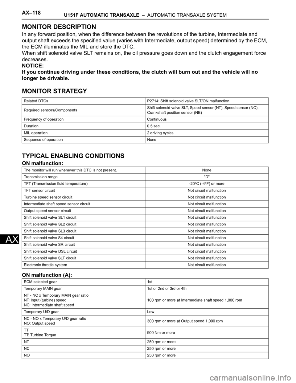
MONITOR DESCRIPTION
In any forward position, when the difference between the revolutions of the turbine, Intermediate and
output shaft exceeds the specified value (varies with Intermediate, output speed) determined by the ECM,
the ECM illuminates the MIL and store the DTC.
When shift solenoid valve SLT remains on, the oil pressure goes down and the clutch engagement force
decreases.
NOTICE:
If you continue driving under these conditions, the clutch will burn out and the vehicle will no
longer be drivable.
MONITOR STRATEGY
TYPICAL ENABLING CONDITIONS
ON malfunction:
ON malfunction (A):
Related DTCs P2714: Shift solenoid valve SLT/ON malfunction
Required sensors/ComponentsShift solenoid valve SLT, Speed sensor (NT), Speed sensor (NC),
Crankshaft position sensor (NE)
Frequency of operation Continuous
Duration 0.5 sec.
MIL operation 2 driving cycles
Sequence of operation None
The monitor will run whenever this DTC is not present. None
Transmission range"D"
TFT (Transmission fluid temperature) -20
C (-4F) or more
TFT sensor circuitNot circuit malfunction
Turbine speed sensor circuit Not circuit malfunction
Intermediate shaft speed sensor circuit Not circuit malfunction
Output speed sensor circuitNot circuit malfunction
Shift solenoid valve SL1 circuit Not circuit malfunction
Shift solenoid valve SL2 circuit Not circuit malfunction
Shift solenoid valve SL3 circuit Not circuit malfunction
Shift solenoid valve S4 circuit Not circuit malfunction
Shift solenoid valve SR circuit Not circuit malfunction
Shift solenoid valve DSL circuit Not circuit malfunction
Shift solenoid valve SLT circuit Not circuit malfunction
Electronic throttle systemNot circuit malfunction
ECM selected gear 1st
Temporary MAIN gear 1st or 2nd or 3rd or 4th
NT - NC x Temporary MAIN gear ratio
NT: Input (turbine) speed
NC: Intermediate shaft speed100 rpm or more at Intermediate shaft speed 1,000 rpm
Temporary U/D gear Low
NC - NO x Temporary U/D gear ratio
NO: Output speed300 rpm or more at Output speed 1,000 rpm
TT
TT: Turbine Torque900 Nm or more
NT 250 rpm or more
NC 250 rpm or more
NO 250 rpm or more