stall TOYOTA SIENNA 2007 Service Repair Manual
[x] Cancel search | Manufacturer: TOYOTA, Model Year: 2007, Model line: SIENNA, Model: TOYOTA SIENNA 2007Pages: 3000, PDF Size: 52.26 MB
Page 22 of 3000
![TOYOTA SIENNA 2007 Service Repair Manual ES–5222GR-FE ENGINE CONTROL SYSTEM – KNOCK SENSOR
ES
(g) Using a 5 mm socket hexagon wrench, remove the
4 bolts [G].
(h) Remove the 2 nuts, 2 bolts and intake air surge tank
[H].
(i) Remove th TOYOTA SIENNA 2007 Service Repair Manual ES–5222GR-FE ENGINE CONTROL SYSTEM – KNOCK SENSOR
ES
(g) Using a 5 mm socket hexagon wrench, remove the
4 bolts [G].
(h) Remove the 2 nuts, 2 bolts and intake air surge tank
[H].
(i) Remove th](/img/14/57466/w960_57466-21.png)
ES–5222GR-FE ENGINE CONTROL SYSTEM – KNOCK SENSOR
ES
(g) Using a 5 mm socket hexagon wrench, remove the
4 bolts [G].
(h) Remove the 2 nuts, 2 bolts and intake air surge tank
[H].
(i) Remove the gasket from the intake air surge tank [I].
9. REMOVE FUEL MAIN TUBE SUB-ASSEMBLY (See
page EM-30)
10. REMOVE INTAKE MANIFOLD (See page EM-39)
11. REMOVE KNOCK CONTROL SENSOR
(a) Disconnect the 2 knock sensor connectors.
(b) Remove the 2 bolts and then remove the 2 knock
control sensors.
INSPECTION
1. KNOCK CONTROL SENSOR
(a) Using an ohmmeter, measure the resistance
between the terminals.
Resistance:
120 to 280 k
at 20C (68F)
If the resistance is not specified, replace the knock
control sensor.
INSTALLATION
1. INSTALL KNOCK CONTROL SENSOR
(a) Install the 2 knock control sensors with the 2 bolts
as shown in the illustration.
Torque: 20 N*m (204 kgf*cm, 15 ft.*lbf)
(b) Connect the 2 knock control sensor connectors.
2. INSTALL INTAKE MANIFOLD (See page EM-49)
3. INSTALL FUEL MAIN TUBE SUB-ASSEMBLY (See
page EM-56)
4. INSTALL INTAKE AIR SURGE TANK
NOTICE:
DO NOT apply oil to the bolts listed below.
A129468E08
A129615
A065174
A132951E01
Tightening PartsTo r q u e
N*m (kgf*cm, ft.*lbf)QTY
Surge Tank and Intake Manifold 18 (184, 13) 4
No. 1 Surge Tank Stay and Surge Tank 21 (214, 15) 1
Throttle Body Bracket and Surge Tank 21 (214, 15) 1
Page 23 of 3000
![TOYOTA SIENNA 2007 Service Repair Manual 2GR-FE ENGINE CONTROL SYSTEM – KNOCK SENSORES–523
ES
(a) Install a new gasket to the intake air surge tank [A].
(b) Using a 5 mm hexagon socket wrench, install the 4
bolts [B].
Torque: 18 N*m ( TOYOTA SIENNA 2007 Service Repair Manual 2GR-FE ENGINE CONTROL SYSTEM – KNOCK SENSORES–523
ES
(a) Install a new gasket to the intake air surge tank [A].
(b) Using a 5 mm hexagon socket wrench, install the 4
bolts [B].
Torque: 18 N*m (](/img/14/57466/w960_57466-22.png)
2GR-FE ENGINE CONTROL SYSTEM – KNOCK SENSORES–523
ES
(a) Install a new gasket to the intake air surge tank [A].
(b) Using a 5 mm hexagon socket wrench, install the 4
bolts [B].
Torque: 18 N*m (184 kgf*cm, 13 ft.*lbf)
(c) Install the intake air surge tank with the 2 nuts and 2
bolts [C].
Torque: Nut
16 N*m (163 kgf*cm, 12 ft.*lbf)
Bolt
21 N*m (214 kgf*cm, 15 ft.*lbf)
(d) Connect the connector [D].
(e) Connect the union to check valve hose [E].
(f) Connect the ventilation hose No. 2 [F].
(g) Install the clamp and connect the throttle with motor
body assembly connector [G].
(h) Connect the vapor feed hose [H].
(i) Connect the 2 water by-pass hoses to the throttle
with motor body assembly [I].
5. INSTALL AIR CLEANER CASE SUB-ASSEMBLY (See
page EM-59)
6. INSTALL AIR CLEANER CAP SUB-ASSEMBLY (See
page ES-496)
7. ADD ENGINE COOLANT (See page CO-7)
8. INSPECT FOR ENGINE COOLANT LEAK (See page
CO-1)
9. INSPECT FOR FUEL LEAK (See page FU-7)
10. INSTALL FRONT OUTER COWL TOP PANEL SUB-
ASSEMBLY (See page EM-61)
11. INSTALL WINDSHIELD WIPER MOTOR ASSEMBLY
HINT:
(See page WW-5)
A129468E09
A129467
A138457E05
A129464E08
Page 24 of 3000

ES–5242GR-FE ENGINE CONTROL SYSTEM – KNOCK SENSOR
ES
12. INSTALL V-BANK COVER SUB-ASSEMBLY (See
page EM-63)
Page 35 of 3000
EM–362GR-FE ENGINE MECHANICAL – ENGINE ASSEMBLY
EM
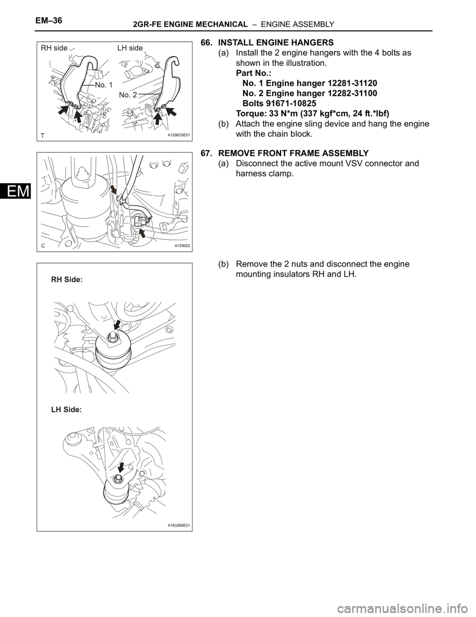
66. INSTALL ENGINE HANGERS
(a) Install the 2 engine hangers with the 4 bolts as
shown in the illustration.
Part No.:
No. 1 Engine hanger 12281-31120
No. 2 Engine hanger 12282-31100
Bolts 91671-10825
Torque: 33 N*m (337 kgf*cm, 24 ft.*lbf)
(b) Attach the engine sling device and hang the engine
with the chain block.
67. REMOVE FRONT FRAME ASSEMBLY
(a) Disconnect the active mount VSV connector and
harness clamp.
(b) Remove the 2 nuts and disconnect the engine
mounting insulators RH and LH.
A129635E01
A155022
A163266E01
Page 44 of 3000
2GR-FE EMISSION CONTROL – EMISSION CONTROL SYSTEMEC–5
EC
ON-VEHICLE INSPECTION
1. INSPECT FUEL CUT RPM
(a) Increase the engine speed to at least 3500 rpm.
(b) Use a sound scope to check for injector operating
sounds.
(c) Check that when the throttle lever is released,
injector operating sounds stop momentarily (at 2500
rpm) and then resume (at 1400 rpm).
Standard
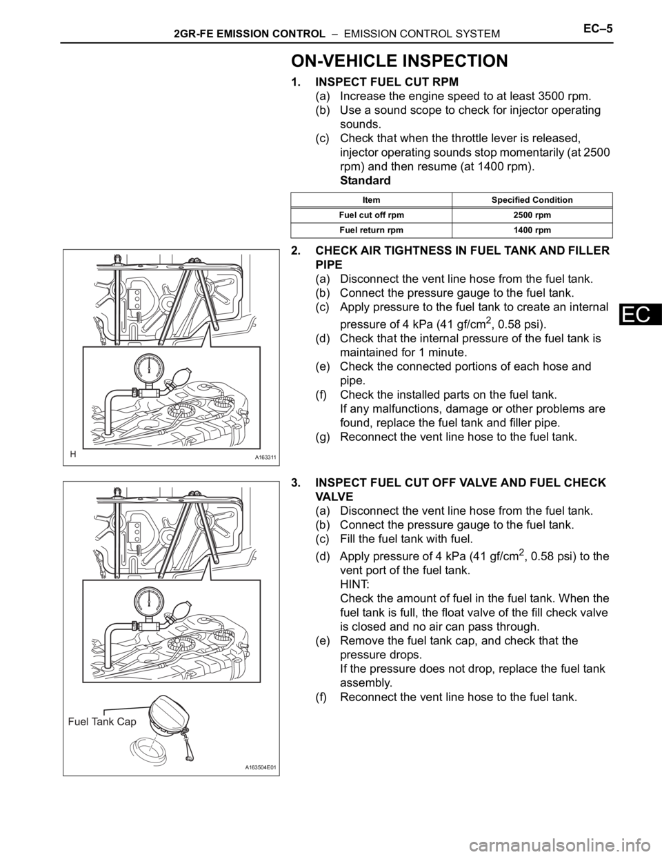
2. CHECK AIR TIGHTNESS IN FUEL TANK AND FILLER
PIPE
(a) Disconnect the vent line hose from the fuel tank.
(b) Connect the pressure gauge to the fuel tank.
(c) Apply pressure to the fuel tank to create an internal
pressure of 4 kPa (41 gf/cm
2, 0.58 psi).
(d) Check that the internal pressure of the fuel tank is
maintained for 1 minute.
(e) Check the connected portions of each hose and
pipe.
(f) Check the installed parts on the fuel tank.
If any malfunctions, damage or other problems are
found, replace the fuel tank and filler pipe.
(g) Reconnect the vent line hose to the fuel tank.
3. INSPECT FUEL CUT OFF VALVE AND FUEL CHECK
VA LV E
(a) Disconnect the vent line hose from the fuel tank.
(b) Connect the pressure gauge to the fuel tank.
(c) Fill the fuel tank with fuel.
(d) Apply pressure of 4 kPa (41 gf/cm
2, 0.58 psi) to the
vent port of the fuel tank.
HINT:
Check the amount of fuel in the fuel tank. When the
fuel tank is full, the float valve of the fill check valve
is closed and no air can pass through.
(e) Remove the fuel tank cap, and check that the
pressure drops.
If the pressure does not drop, replace the fuel tank
assembly.
(f) Reconnect the vent line hose to the fuel tank.
Item Specified Condition
Fuel cut off rpm 2500 rpm
Fuel return rpm 1400 rpm
A163311
A163504E01
Page 47 of 3000
IT–62GR-FE INTAKE – INTAKE AIR CONTROL VALVE
IT
INSPECTION
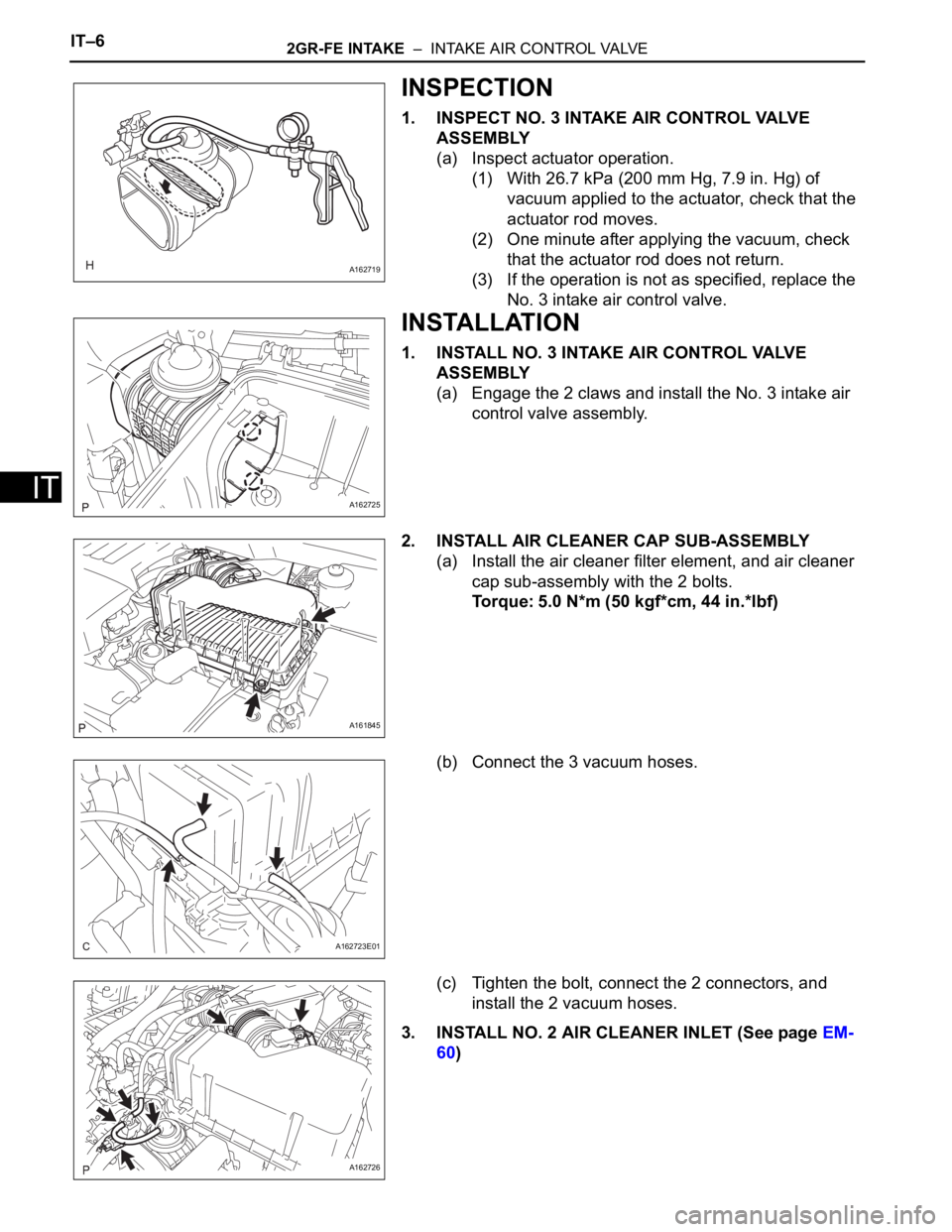
1. INSPECT NO. 3 INTAKE AIR CONTROL VALVE
ASSEMBLY
(a) Inspect actuator operation.
(1) With 26.7 kPa (200 mm Hg, 7.9 in. Hg) of
vacuum applied to the actuator, check that the
actuator rod moves.
(2) One minute after applying the vacuum, check
that the actuator rod does not return.
(3) If the operation is not as specified, replace the
No. 3 intake air control valve.
INSTALLATION
1. INSTALL NO. 3 INTAKE AIR CONTROL VALVE
ASSEMBLY
(a) Engage the 2 claws and install the No. 3 intake air
control valve assembly.
2. INSTALL AIR CLEANER CAP SUB-ASSEMBLY
(a) Install the air cleaner filter element, and air cleaner
cap sub-assembly with the 2 bolts.
Torque: 5.0 N*m (50 kgf*cm, 44 in.*lbf)
(b) Connect the 3 vacuum hoses.
(c) Tighten the bolt, connect the 2 connectors, and
install the 2 vacuum hoses.
3. INSTALL NO. 2 AIR CLEANER INLET (See page EM-
60)
A162719
A162725
A161845
A162723E01
A162726
Page 62 of 3000
IN–32INTRODUCTION – HOW TO TROUBLESHOOT ECU CONTROLLED SYSTEMS
IN
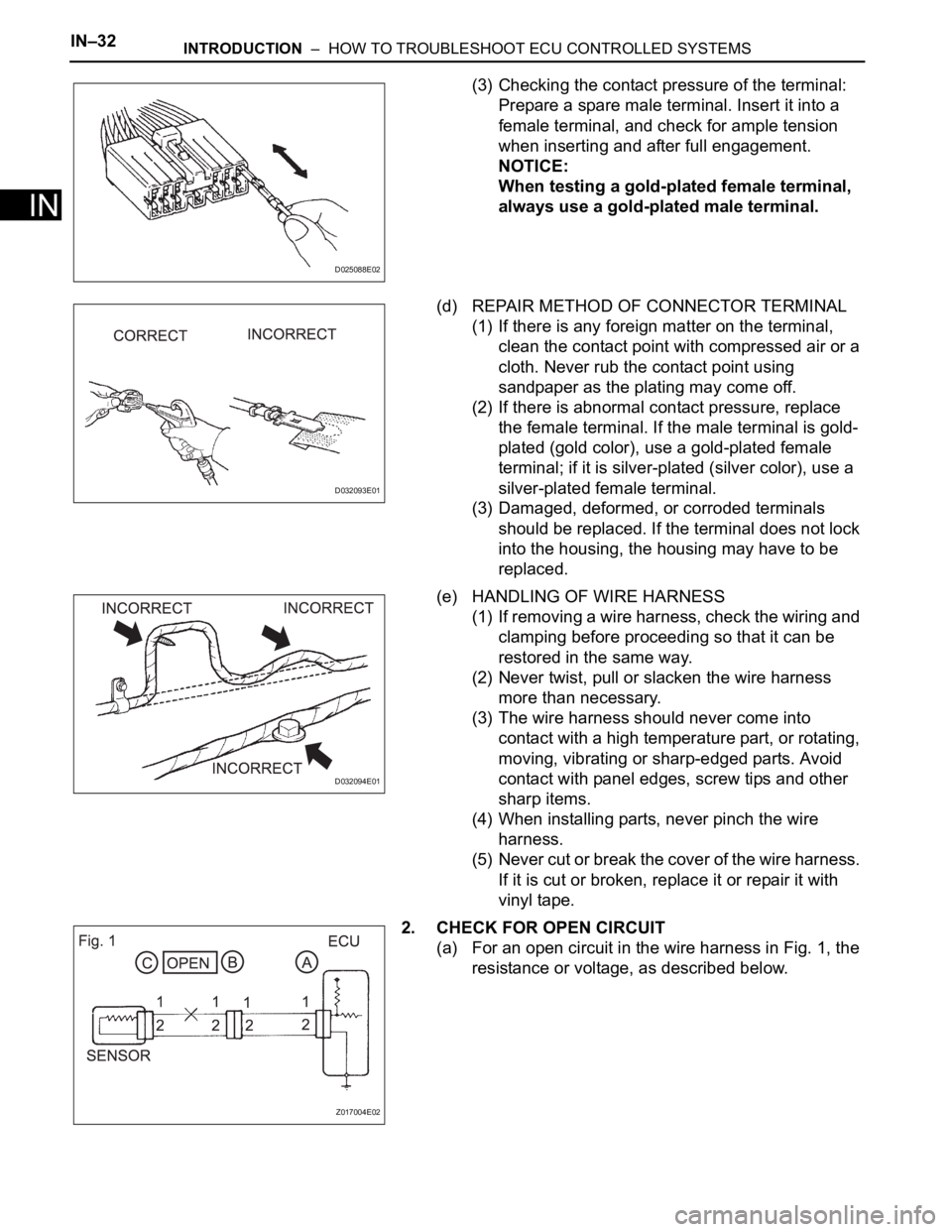
(3) Checking the contact pressure of the terminal:
Prepare a spare male terminal. Insert it into a
female terminal, and check for ample tension
when inserting and after full engagement.
NOTICE:
When testing a gold-plated female terminal,
always use a gold-plated male terminal.
(d) REPAIR METHOD OF CONNECTOR TERMINAL
(1) If there is any foreign matter on the terminal,
clean the contact point with compressed air or a
cloth. Never rub the contact point using
sandpaper as the plating may come off.
(2) If there is abnormal contact pressure, replace
the female terminal. If the male terminal is gold-
plated (gold color), use a gold-plated female
terminal; if it is silver-plated (silver color), use a
silver-plated female terminal.
(3) Damaged, deformed, or corroded terminals
should be replaced. If the terminal does not lock
into the housing, the housing may have to be
replaced.
(e) HANDLING OF WIRE HARNESS
(1) If removing a wire harness, check the wiring and
clamping before proceeding so that it can be
restored in the same way.
(2) Never twist, pull or slacken the wire harness
more than necessary.
(3) The wire harness should never come into
contact with a high temperature part, or rotating,
moving, vibrating or sharp-edged parts. Avoid
contact with panel edges, screw tips and other
sharp items.
(4) When installing parts, never pinch the wire
harness.
(5) Never cut or break the cover of the wire harness.
If it is cut or broken, replace it or repair it with
vinyl tape.
2. CHECK FOR OPEN CIRCUIT
(a) For an open circuit in the wire harness in Fig. 1, the
resistance or voltage, as described below.
D025088E02
D032093E01
D032094E01
Z017004E02
Page 80 of 3000
IG–62GR-FE IGNITION – IGNITION COIL AND SPARK PLUG
IG
ON-VEHICLE INSPECTION
NOTICE:
In this section, the terms "cold" and "hot" refer to the
temperature of the coils. "Cold" means approximately -
10
C (14F) to 50C (122F). "Hot" means approximately
50
C (122F) to 100C (212F).
1. INSPECT IGNITION COIL ASSEMBLY
(a) Check for DTCs.
NOTICE:
If any DTC is present, perform troubleshooting
in accordance with the procedures for that DTC.
(b) Remove the ignition coil assembly and spark plug.
(See page IG-8).
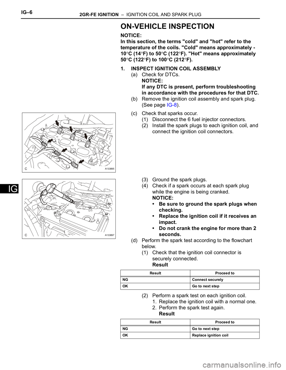
(c) Check that sparks occur.
(1) Disconnect the 6 fuel injector connectors.
(2) Install the spark plugs to each ignition coil, and
connect the ignition coil connectors.
(3) Ground the spark plugs.
(4) Check if a spark occurs at each spark plug
while the engine is being cranked.
NOTICE:
• Be sure to ground the spark plugs when
checking.
• Replace the ignition coil if it receives an
impact.
• Do not crank the engine for more than 2
seconds.
(d) Perform the spark test according to the flowchart
below.
(1) Check that the ignition coil connector is
securely connected.
Result
(2) Perform a spark test on each ignition coil.
1. Replace the ignition coil with a normal one.
2. Perform the spark test again.
Result
A133895
A133897
Result Proceed to
NG Connect securely
OK Go to next step
Result Proceed to
NG Go to next step
OK Replace ignition coil
Page 81 of 3000
2GR-FE IGNITION – IGNITION COIL AND SPARK PLUGIG–7
IG
(3) Check the spark plug (See page EM-1).
Result
(4) Check the power supply to the ignition coil.
1. Turn the ignition switch to the ON position.
2. Check that there is battery voltage at the
ignition coil positive (+) terminal.
Result
(5) Measure the resistance of the crankshaft
position sensor (See page ES-514).
Result
(6) Check the IGT signal from the ECM (See page
ES-233)
Result
(e) Using a 16 mm (0.63 in.) plug wrench, install the
spark plugs.
Torque: 18 N*m (184 kgf*cm, 13 ft.*lbf)
(f) Connect the 6 fuel injector connectors.
(g) Install the ignition coil assembly (See page IG-10).
2. INSPECT SPARK PLUG
NOTICE:
• Never use a wire brush for cleaning.
• Never attempt to adjust the electrode gap on a
used spark plug.
(a) Check the electrode.
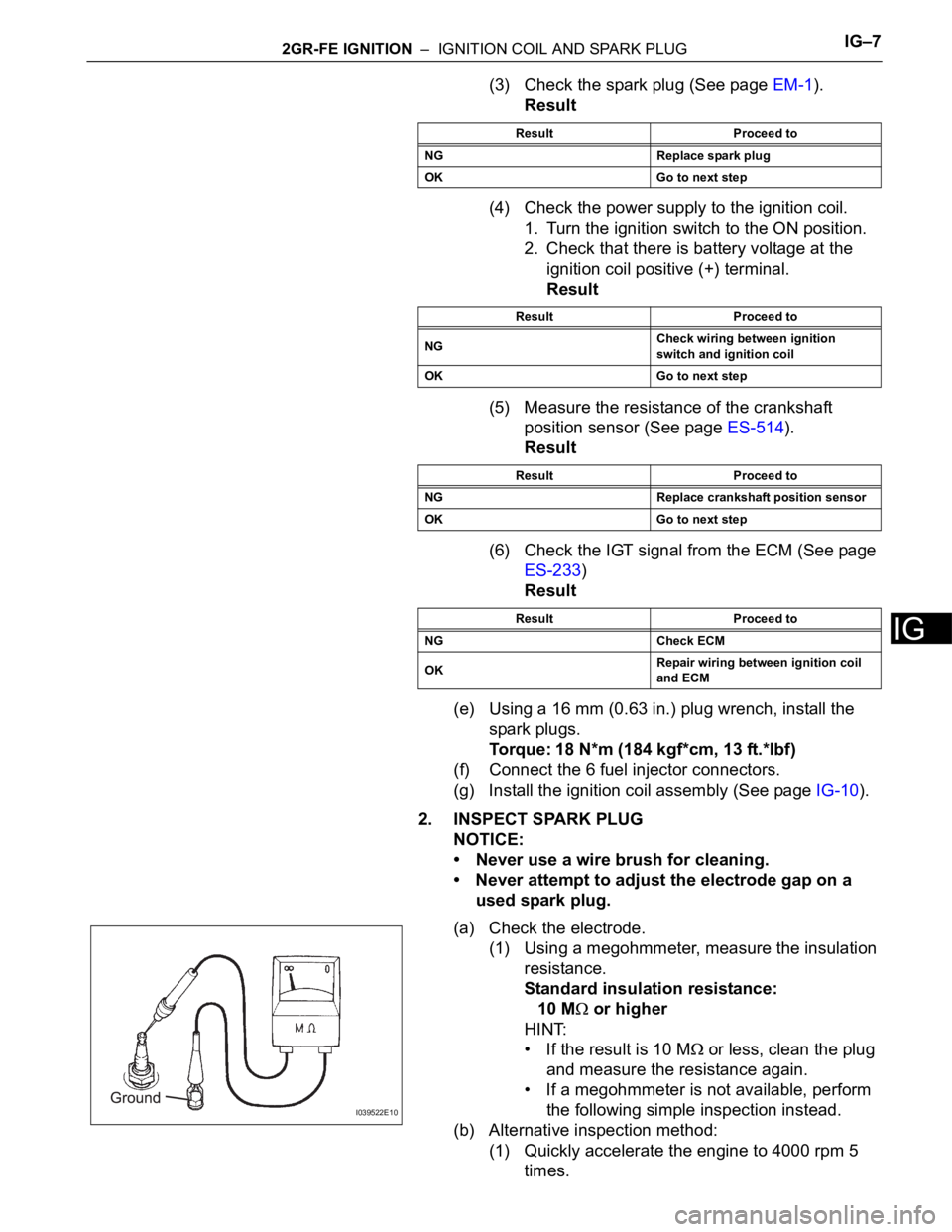
(1) Using a megohmmeter, measure the insulation
resistance.
Standard insulation resistance:
10 M
or higher
HINT:
• If the result is 10 M
or less, clean the plug
and measure the resistance again.
• If a megohmmeter is not available, perform
the following simple inspection instead.
(b) Alternative inspection method:
(1) Quickly accelerate the engine to 4000 rpm 5
times.
Result Proceed to
NG Replace spark plug
OK Go to next step
Result Proceed to
NGCheck wiring between ignition
switch and ignition coil
OK Go to next step
Result Proceed to
NG Replace crankshaft position sensor
OK Go to next step
Result Proceed to
NG Check ECM
OKRepair wiring between ignition coil
and ECM
I039522E10
Page 82 of 3000
IG–82GR-FE IGNITION – IGNITION COIL AND SPARK PLUG
IG
(2) Remove the spark plugs.
(3) Visually check the spark plug.
If the electrode is dry, the spark plug is
functioning properly. If the electrode is damp,
proceed to the next step.
(c) Check the spark plug for any damage to its threads
and insulator. If there is damage, replace the spark
plug.
Recommended spark plug
NOTICE:
Use only the listed spark plug or equivalent to
ensure engine performance and smooth
driveability.
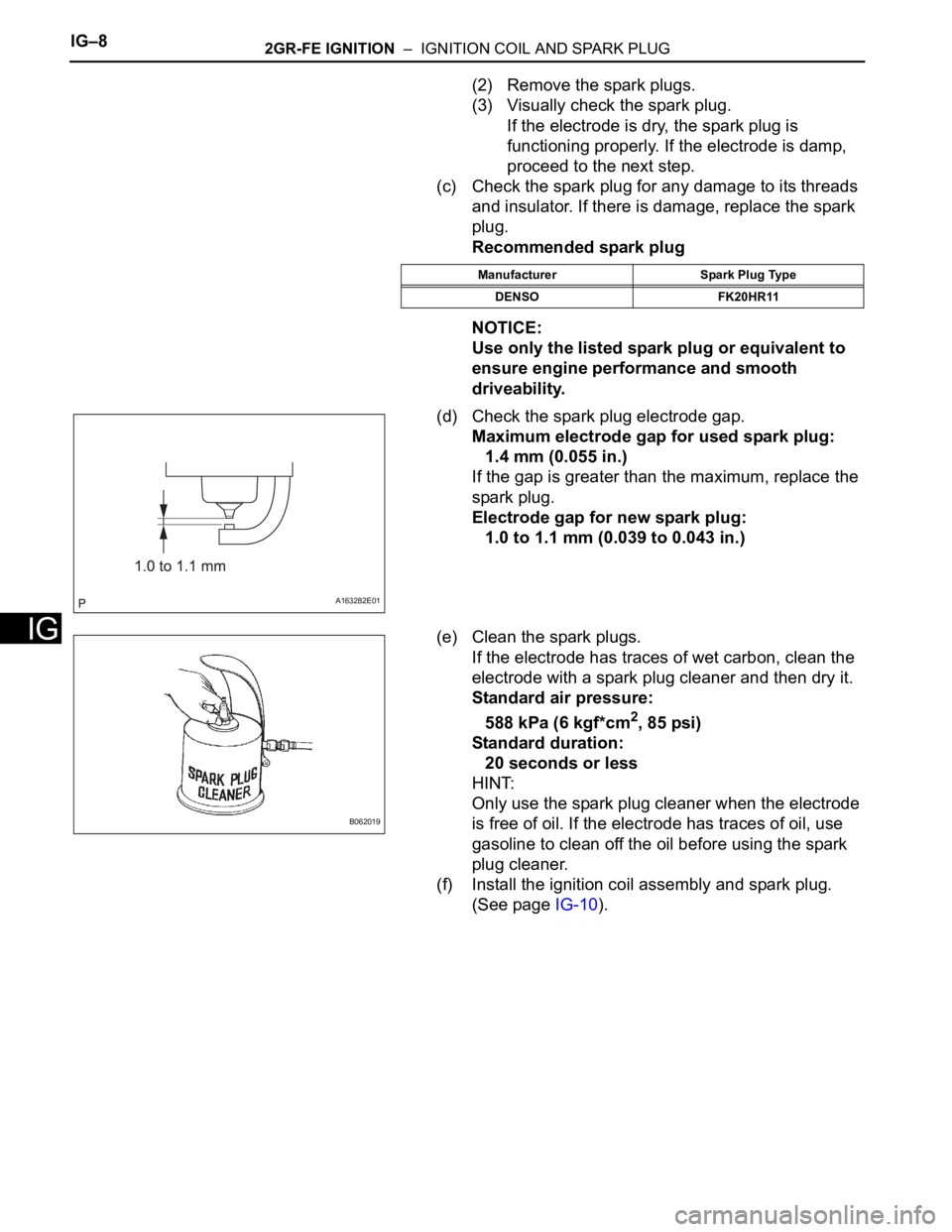
(d) Check the spark plug electrode gap.
Maximum electrode gap for used spark plug:
1.4 mm (0.055 in.)
If the gap is greater than the maximum, replace the
spark plug.
Electrode gap for new spark plug:
1.0 to 1.1 mm (0.039 to 0.043 in.)
(e) Clean the spark plugs.
If the electrode has traces of wet carbon, clean the
electrode with a spark plug cleaner and then dry it.
Standard air pressure:
588 kPa (6 kgf*cm
2, 85 psi)
Standard duration:
20 seconds or less
HINT:
Only use the spark plug cleaner when the electrode
is free of oil. If the electrode has traces of oil, use
gasoline to clean off the oil before using the spark
plug cleaner.
(f) Install the ignition coil assembly and spark plug.
(See page IG-10).
Manufacturer Spark Plug Type
DENSO FK20HR11
A163282E01
B062019