TOYOTA SUPRA 1995 Service Repair Manual
SUPRA 1995
TOYOTA
TOYOTA
https://www.carmanualsonline.info/img/14/57468/w960_57468-0.png
TOYOTA SUPRA 1995 Service Repair Manual
Trending: wiper fluid, ground clearance, fuel consumption, Engine mechanical, heating, fuel pump, trip computer
Page 1301 of 2543
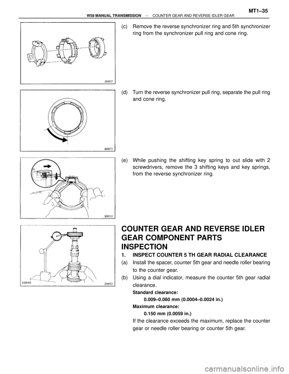
(c) Remove the reverse synchronizer ring and 5th synchronizer
ring from the synchronizer pull ring and cone ring.
(d) Turn the reverse synchronizer pull ring, separate the pull ring
and cone ring.
(e) While pushing the shifting key spring to out slide with 2
screwdrivers, remove the 3 shifting keys and key springs,
from the reverse synchronizer ring.
COUNTER GEAR AND REVERSE IDLER
GEAR COMPONENT PARTS
INSPECTION
1. INSPECT COUNTER 5 TH GEAR RADIAL CLEARANCE
(a) Install the spacer, counter 5th gear and needle roller bearing
to the counter gear.
(b) Using a dial indicator, measure the counter 5th gear radial
clearance.
Standard clearance:
0.009±0.060 mm (0.0004±0.0024 in.)
Maximum clearance:
0.150 mm (0.0059 in.)
If the clearance exceeds the maximum, replace the counter
gear or needle roller bearing or counter 5th gear.
± W58 MANUAL TRANSMISSIONCOUNTER GEAR AND REVERSE IDLER GEARMT1±35
Page 1302 of 2543
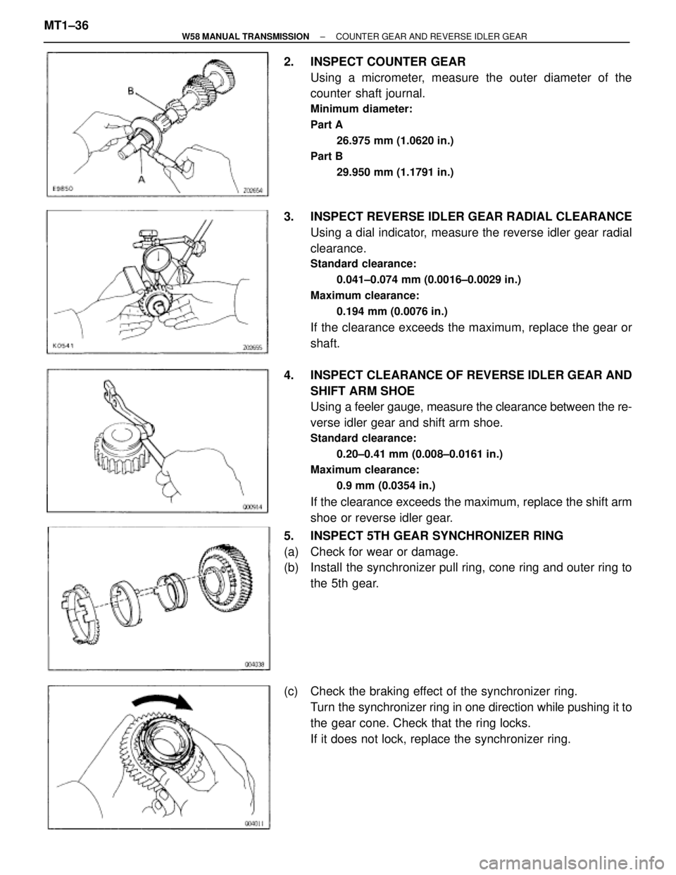
2. INSPECT COUNTER GEAR
Using a micrometer, measure the outer diameter of the
counter shaft journal.
Minimum diameter:
Part A
26.975 mm (1.0620 in.)
Part B
29.950 mm (1.1791 in.)
3. INSPECT REVERSE IDLER GEAR RADIAL CLEARANCE
Using a dial indicator, measure the reverse idler gear radial
clearance.
Standard clearance:
0.041±0.074 mm (0.0016±0.0029 in.)
Maximum clearance:
0.194 mm (0.0076 in.)
If the clearance exceeds the maximum, replace the gear or
shaft.
4. INSPECT CLEARANCE OF REVERSE IDLER GEAR AND
SHIFT ARM SHOE
Using a feeler gauge, measure the clearance between the re-
verse idler gear and shift arm shoe.
Standard clearance:
0.20±0.41 mm (0.008±0.0161 in.)
Maximum clearance:
0.9 mm (0.0354 in.)
If the clearance exceeds the maximum, replace the shift arm
shoe or reverse idler gear.
5. INSPECT 5TH GEAR SYNCHRONIZER RING
(a) Check for wear or damage.
(b) Install the synchronizer pull ring, cone ring and outer ring to
the 5th gear.
(c) Check the braking effect of the synchronizer ring.
Turn the synchronizer ring in one direction while pushing it to
the gear cone. Check that the ring locks.
If it does not lock, replace the synchronizer ring. MT1±36
± W58 MANUAL TRANSMISSIONCOUNTER GEAR AND REVERSE IDLER GEAR
Page 1303 of 2543
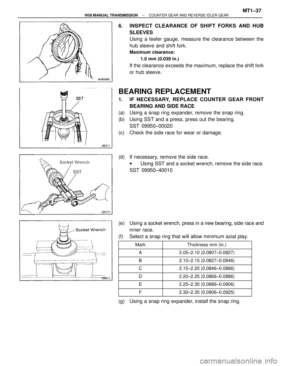
6. INSPECT CLEARANCE OF SHIFT FORKS AND HUB
SLEEVES
Using a feeler gauge, measure the clearance between the
hub sleeve and shift fork.
Maximum clearance:
1.0 mm (0.039 in.)
If the clearance exceeds the maximum, replace the shift fork
or hub sleeve.
BEARING REPLACEMENT
1. IF NECESSARY, REPLACE COUNTER GEAR FRONT
BEARING AND SIDE RACE
(a) Using a snap ring expander, remove the snap ring.
(b) Using SST and a press, press out the bearing.
SST 09950±00020
(c) Check the side race for wear or damage.
(d) If necessary, remove the side race.
wUsing SST and a socket wrench, remove the side race.
SST 09950±40010
(e) Using a socket wrench, press in a new bearing, side race and
inner race.
(f) Select a snap ring that will allow minimum axial play.
������� �
������ �������Mark
�������������� �
������������� ��������������Thickness mm (in.)
������� �������A�������������� ��������������2.05±2.10 (0.0807±0.0827)
������� �������B�������������� ��������������2.10±2.15 (0.0827±0.0846)
������� �������C�������������� ��������������2.15±2.20 (0.0846±0.0866)
������� �������D�������������� ��������������2.20±2.25 (0.0866±0.0886)
������� �������E�������������� ��������������2.25±2.30 (0.0886±0.0906)
������� �������F�������������� ��������������2.30±2.35 (0.0906±0.0925)
(g) Using a snap ring expander, install the snap ring.
± W58 MANUAL TRANSMISSIONCOUNTER GEAR AND REVERSE IDLER GEARMT1±37
Page 1304 of 2543
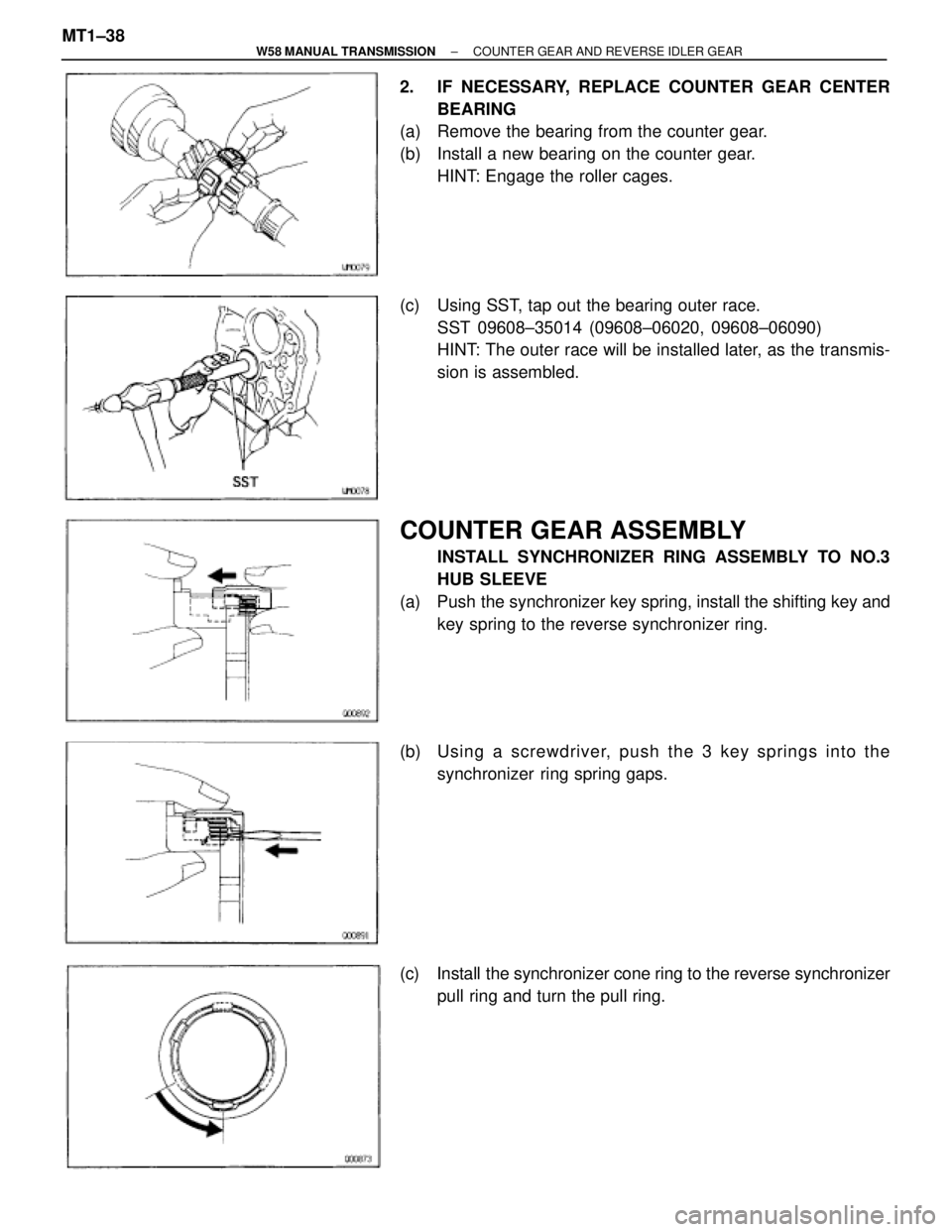
2. IF NECESSARY, REPLACE COUNTER GEAR CENTER
BEARING
(a) Remove the bearing from the counter gear.
(b) Install a new bearing on the counter gear.
HINT: Engage the roller cages.
(c) Using SST, tap out the bearing outer race.
SST 09608±35014 (09608±06020, 09608±06090)
HINT: The outer race will be installed later, as the transmis-
sion is assembled.
COUNTER GEAR ASSEMBLY
INSTALL SYNCHRONIZER RING ASSEMBLY TO NO.3
HUB SLEEVE
(a) Push the synchronizer key spring, install the shifting key and
key spring to the reverse synchronizer ring.
(b) Usin g a scre wd rive r, pu sh th e 3 ke y sp rin g s in to th e
synchronizer ring spring gaps.
(c) Install the synchronizer cone ring to the reverse synchronizer
pull ring and turn the pull ring. MT1±38
± W58 MANUAL TRANSMISSIONCOUNTER GEAR AND REVERSE IDLER GEAR
Page 1305 of 2543
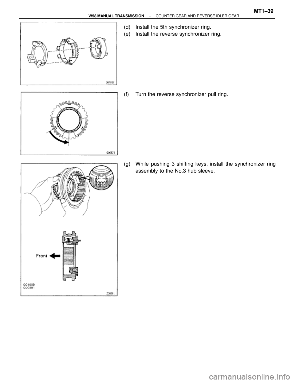
(d) Install the 5th synchronizer ring.
(e) Install the reverse synchronizer ring.
(f) Turn the reverse synchronizer pull ring.
(g) While pushing 3 shifting keys, install the synchronizer ring
assembly to the No.3 hub sleeve.
± W58 MANUAL TRANSMISSIONCOUNTER GEAR AND REVERSE IDLER GEARMT1±39
Page 1306 of 2543
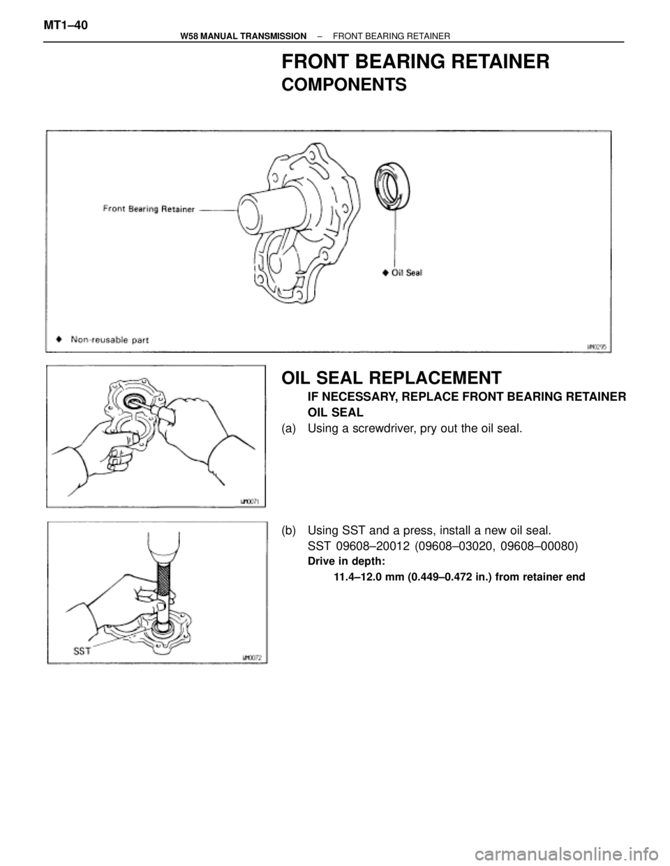
FRONT BEARING RETAINER
COMPONENTS
OIL SEAL REPLACEMENT
IF NECESSARY, REPLACE FRONT BEARING RETAINER
OIL SEAL
(a) Using a screwdriver, pry out the oil seal.
(b) Using SST and a press, install a new oil seal.
SST 09608±20012 (09608±03020, 09608±00080)
Drive in depth:
11.4±12.0 mm (0.449±0.472 in.) from retainer end
MT1±40± W58 MANUAL TRANSMISSIONFRONT BEARING RETAINER
Page 1307 of 2543
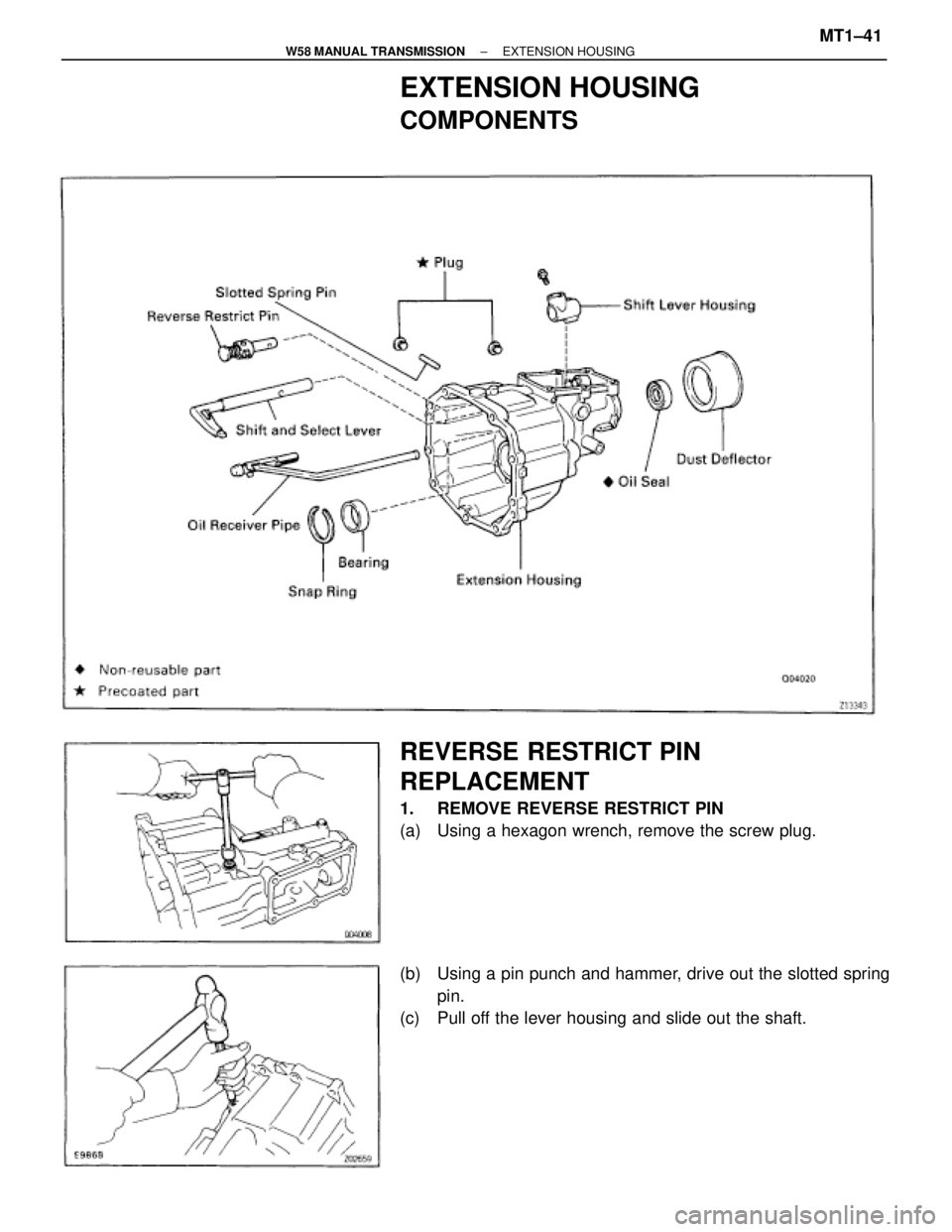
EXTENSION HOUSING
COMPONENTS
REVERSE RESTRICT PIN
REPLACEMENT
1. REMOVE REVERSE RESTRICT PIN
(a) Using a hexagon wrench, remove the screw plug.
(b) Using a pin punch and hammer, drive out the slotted spring
pin.
(c) Pull off the lever housing and slide out the shaft.
± W58 MANUAL TRANSMISSIONEXTENSION HOUSINGMT1±41
Page 1308 of 2543
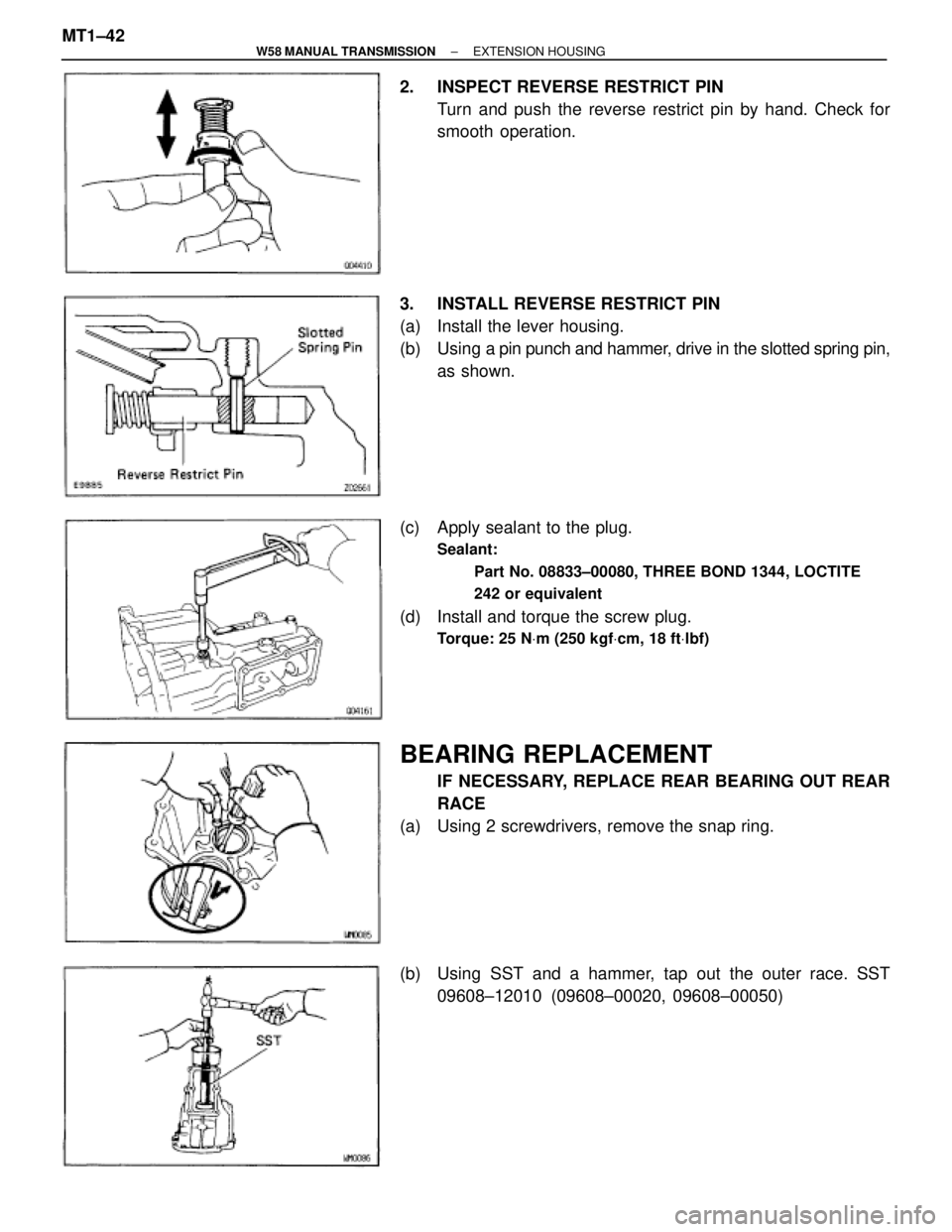
2. INSPECT REVERSE RESTRICT PIN
Turn and push the reverse restrict pin by hand. Check for
smooth operation.
3. INSTALL REVERSE RESTRICT PIN
(a) Install the lever housing.
(b) Using a pin punch and hammer, drive in the slotted spring pin,
as shown.
(c) Apply sealant to the plug.
Sealant:
Part No. 08833±00080, THREE BOND 1344, LOCTITE
242 or equivalent
(d) Install and torque the screw plug.
Torque: 25 NVm (250 kgfVcm, 18 ftVlbf)
BEARING REPLACEMENT
IF NECESSARY, REPLACE REAR BEARING OUT REAR
RACE
(a) Using 2 screwdrivers, remove the snap ring.
(b) Using SST and a hammer, tap out the outer race. SST
09608±12010 (09608±00020, 09608±00050) MT1±42
± W58 MANUAL TRANSMISSIONEXTENSION HOUSING
Page 1309 of 2543
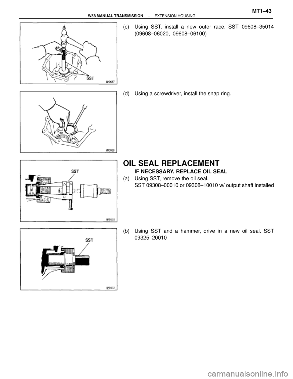
(c) Using SST, install a new outer race. SST 09608±35014
(09608±06020, 09608±06100)
(d) Using a screwdriver, install the snap ring.
OIL SEAL REPLACEMENT
IF NECESSARY, REPLACE OIL SEAL
(a) Using SST, remove the oil seal.
SST 09308±00010 or 09308±10010 w/ output shaft installed
(b) Using SST and a hammer, drive in a new oil seal. SST
09325±20010
± W58 MANUAL TRANSMISSIONEXTENSION HOUSINGMT1±43
Page 1310 of 2543
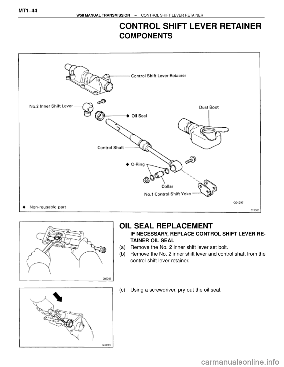
CONTROL SHIFT LEVER RETAINER
COMPONENTS
OIL SEAL REPLACEMENT
IF NECESSARY, REPLACE CONTROL SHIFT LEVER RE-
TAINER OIL SEAL
(a) Remove the No. 2 inner shift lever set bolt.
(b) Remove the No. 2 inner shift lever and control shaft from the
control shift lever retainer.
(c) Using a screwdriver, pry out the oil seal. MT1±44
± W58 MANUAL TRANSMISSIONCONTROL SHIFT LEVER RETAINER
Trending: fuse, maintenance, seats, oil viscosity, engine overheat, catalytic converter, start stop button
