TOYOTA SUPRA 1995 Service Manual PDF
SUPRA 1995
TOYOTA
TOYOTA
https://www.carmanualsonline.info/img/14/57468/w960_57468-0.png
TOYOTA SUPRA 1995 Service Manual PDF
Trending: overheating, set clock, spark plugs, clock, light, instrument panel, headlight aiming
Page 61 of 2543
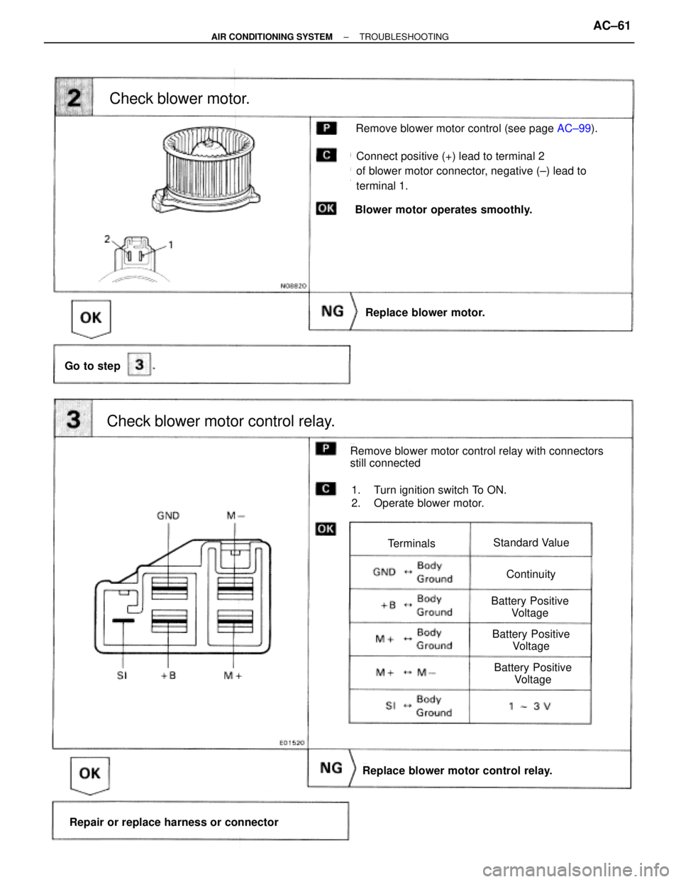
(See page AC±99).
Check blower motor.
Go to step
Replace blower motor.
Check blower motor control relay.
Replace blower motor control relay.
Repair or replace harness or connector
Remove blower motor control relay with connectors
still connected
1. Turn ignition switch To ON.
2. Operate blower motor.
TerminalsStandard Value
Continuity
Battery Positive
Voltage
Battery Positive
Voltage
Battery Positive
Voltage
Connect positive (+) lead to terminal 2
of blower motor connector, negative (±) lead to
terminal 1.
Remove blower motor control (see page AC±99).
Blower motor operates smoothly.
± AIR CONDITIONING SYSTEMTROUBLESHOOTINGAC±61
Page 62 of 2543
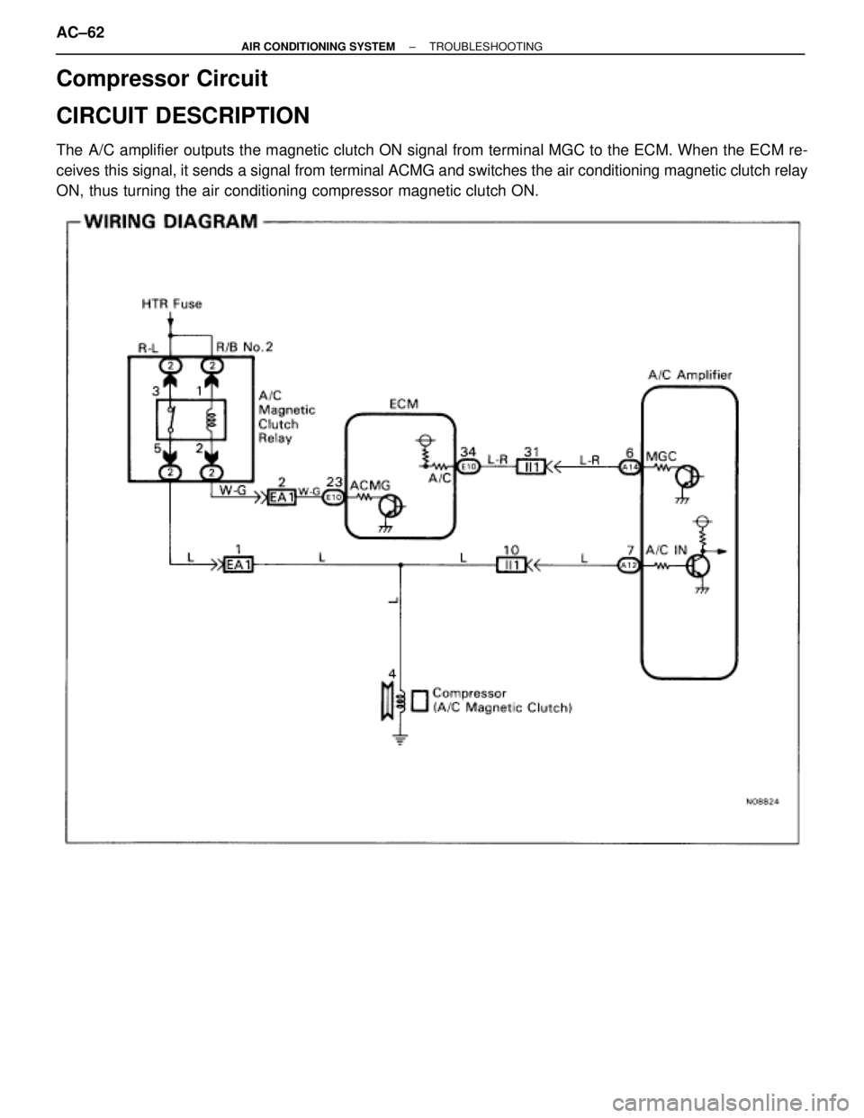
Compressor Circuit
CIRCUIT DESCRIPTION
The A/C amplifier outputs the magnetic clutch ON signal from terminal MGC to the ECM. When the ECM re-
ceives this signal, it sends a signal from terminal ACMG and switches the air conditioning magnetic clutch relay
ON, thus turning the air conditioning compressor magnetic clutch ON.
AC±62± AIR CONDITIONING SYSTEMTROUBLESHOOTING
Page 63 of 2543
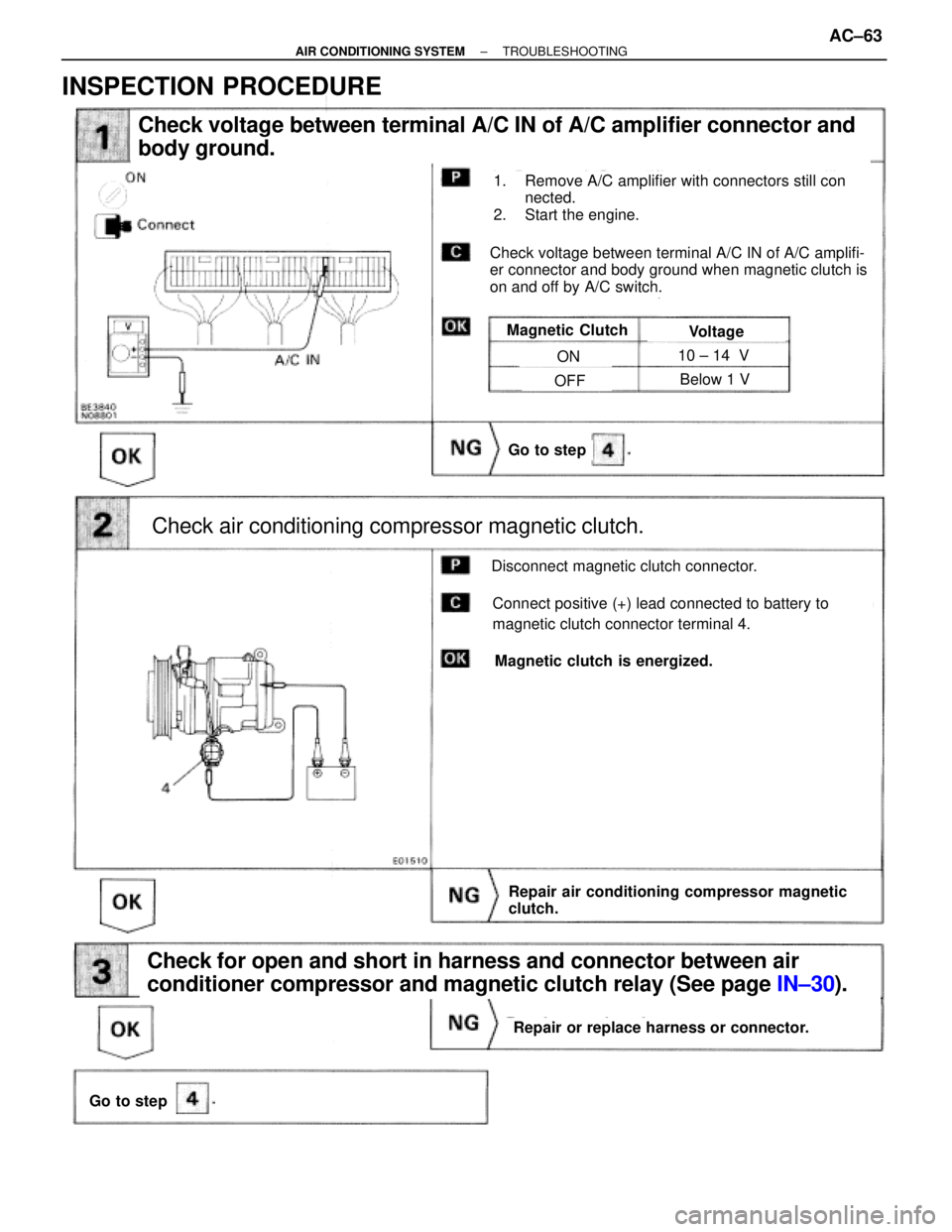
Check voltage between terminal A/C IN of A/C amplifier connector and
body ground.
Check air conditioning compressor magnetic clutch.
Go to step
Check for open and short in harness and connector between air
conditioner compressor and magnetic clutch relay (See page IN±30).
Repair or replace harness or connector.
Go to step
1. Remove A/C amplifier with connectors still con
nected.
2. Start the engine.
Check voltage between terminal A/C IN of A/C amplifi-
er connector and body ground when magnetic clutch is
on and off by A/C switch.
Magnetic ClutchVoltage
ON
OFF Below 1 V
Connect positive (+) lead connected to battery to
magnetic clutch connector terminal 4.
Disconnect magnetic clutch connector.
Magnetic clutch is energized.
Repair air conditioning compressor magnetic
clutch.
10 ± 14 V
INSPECTION PROCEDURE
± AIR CONDITIONING SYSTEMTROUBLESHOOTINGAC±63
Page 64 of 2543
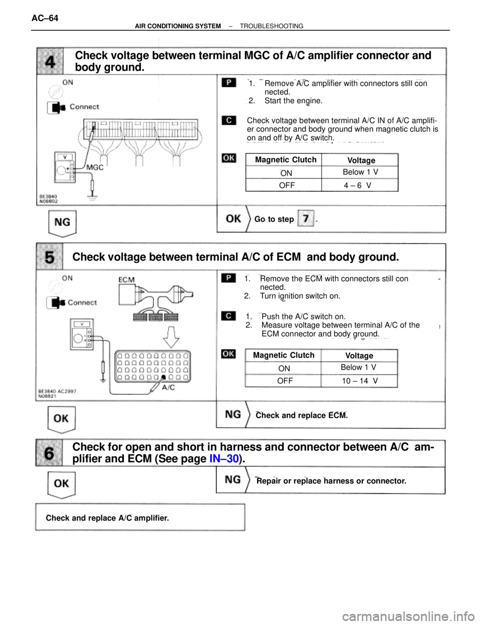
Go to step
Check and replace ECM.
Check voltage between terminal A/C of ECM and body ground.
Check voltage between terminal MGC of A/C amplifier connector and
body ground.
Magnetic ClutchVoltage
ON
OFF
Below 1 V
4 ± 6 V
1. Remove A/C amplifier with connectors still con
nected.
2. Start the engine.
Check voltage between terminal A/C IN of A/C amplifi-
er connector and body ground when magnetic clutch is
on and off by A/C switch.
1. Remove the ECM with connectors still con
nected.
2. Turn ignition switch on.
Magnetic ClutchVoltage
ON
OFF
Below 1 V
10 ± 14 V
Check and replace A/C amplifier.
Repair or replace harness or connector.
Check for open and short in harness and connector between A/C am-
plifier and ECM (See page IN±30).
1. Push the A/C switch on.
2. Measure voltage between terminal A/C of the
ECM connector and body ground.
AC±64± AIR CONDITIONING SYSTEMTROUBLESHOOTING
Page 65 of 2543
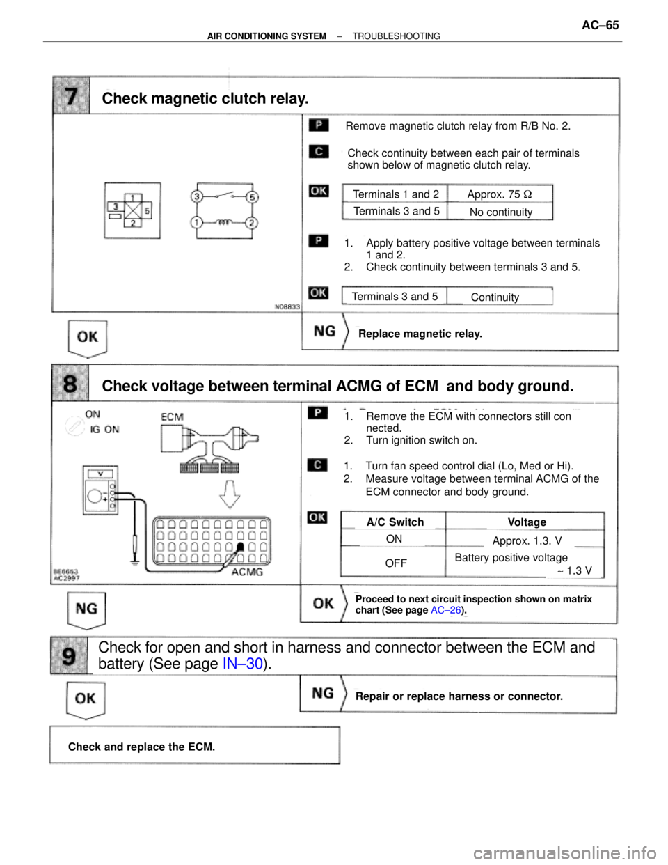
Remove magnetic clutch relay from R/B No. 2.
Check continuity between each pair of terminals
shown below of magnetic clutch relay.
Terminals 1 and 2
Terminals 3 and 5
Terminals 3 and 5
No continuity
Continuity
Replace magnetic relay.
Check and replace the ECM.
Repair or replace harness or connector.
A/C SwitchVoltage
ON
OFF
Check for open and short in harness and connector between the ECM and
battery (See page IN±30).
Approx. 1.3. V
Approx. 75 �
Battery positive voltage
Check magnetic clutch relay.
Check voltage between terminal ACMG of ECM and body ground.
1. Apply battery positive voltage between terminals
1 and 2.
2. Check continuity between terminals 3 and 5.
1. Remove the ECM with connectors still con
nected.
2. Turn ignition switch on.
1. Turn fan speed control dial (Lo, Med or Hi).
2. Measure voltage between terminal ACMG of the
ECM connector and body ground.
Proceed to next circuit inspection shown on matrix
chart (See page AC±26).
~ 1.3 V
± AIR CONDITIONING SYSTEMTROUBLESHOOTINGAC±65
Page 66 of 2543
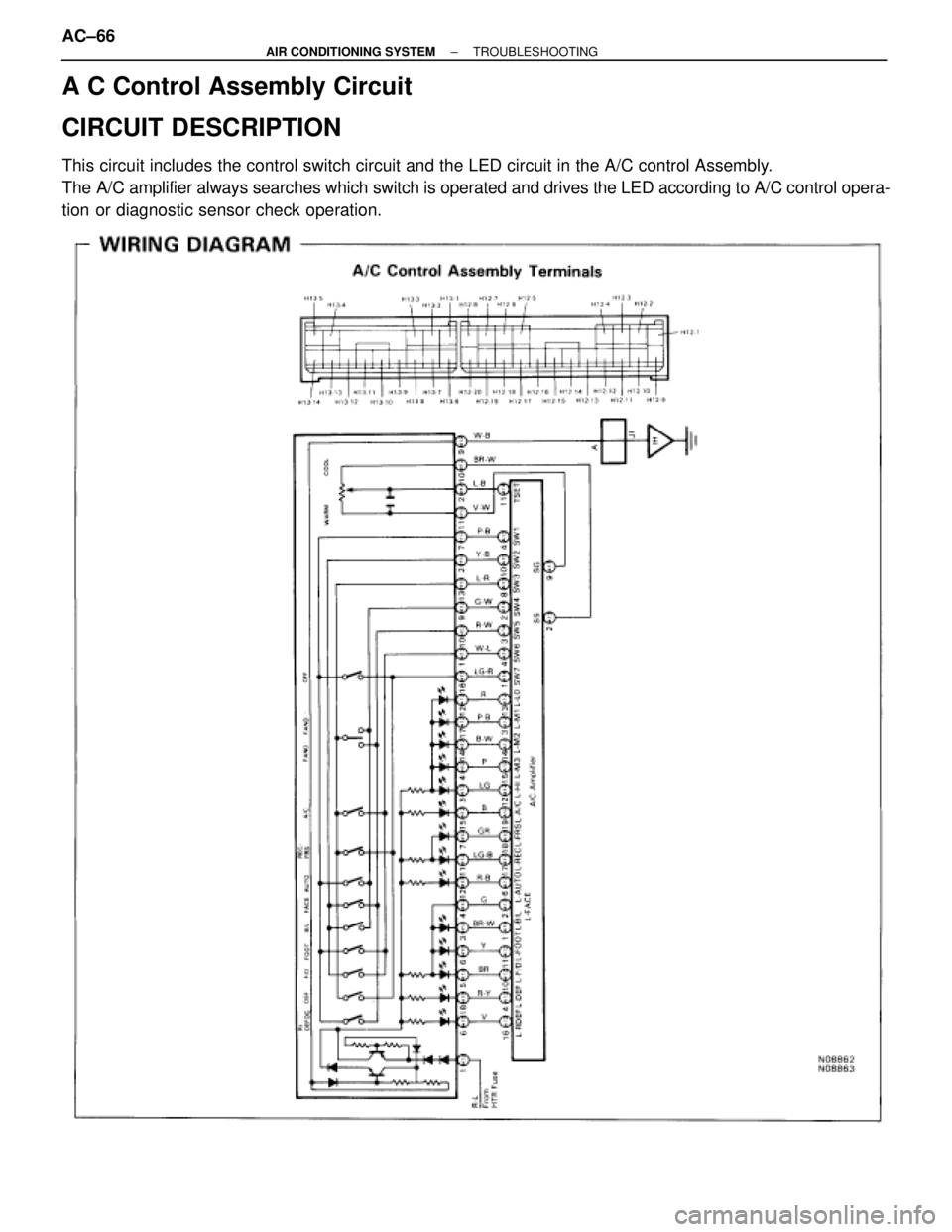
A C Control Assembly Circuit
CIRCUIT DESCRIPTION
This circuit includes the control switch circuit and the LED circuit in the A/C control Assembly.
The A/C amplifier always searches which switch is operated and drives the LED according to A/C control opera-
tion or diagnostic sensor check operation.
AC±66± AIR CONDITIONING SYSTEMTROUBLESHOOTING
Page 67 of 2543
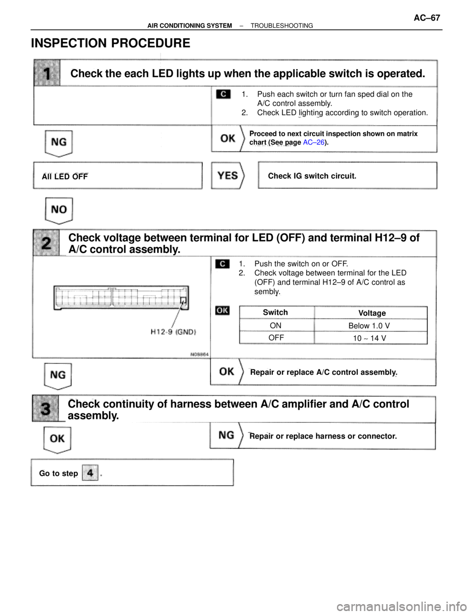
INSPECTION PROCEDURE
Check the each LED lights up when the applicable switch is operated.
Proceed to next circuit inspection shown on matrix
chart (See page AC±26).
Check voltage between terminal for LED (OFF) and terminal H12±9 of
A/C control assembly.
Check continuity of harness between A/C amplifier and A/C control
assembly.
Go to step
Repair or replace harness or connector.
Repair or replace A/C control assembly.
Switch
ON
OFF
Below 1.0 V
10 ~ 14 V
Voltage
All LED OFFCheck IG switch circuit.
1. Push the switch on or OFF.
2. Check voltage between terminal for the LED
(OFF) and terminal H12±9 of A/C control as
sembly.
1. Push each switch or turn fan sped dial on the
A/C control assembly.
2. Check LED lighting according to switch operation.
± AIR CONDITIONING SYSTEMTROUBLESHOOTINGAC±67
Page 68 of 2543
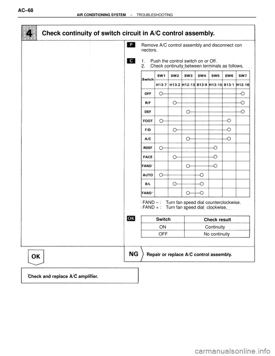
Repair or replace A/C control assembly.
Check and replace A/C amplifier.
SwitchCheck result
ON
OFFNo continuity
Continuity
Remove A/C control assembly and disconnect con
nectors.
Check continuity of switch circuit in A/C control assembly.
1. Push the control switch on or Off.
2. Check continuity between terminals as follows.
FAND ± : Turn fan speed dial counterclockwise.
FAND + : Turn fan speed dial clockwise.
AC±68± AIR CONDITIONING SYSTEMTROUBLESHOOTING
Page 69 of 2543
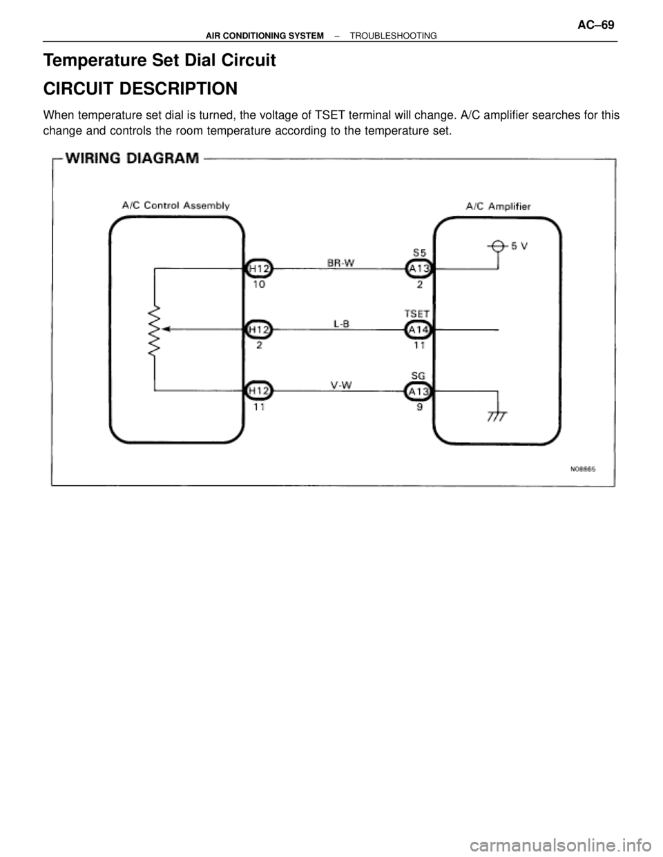
Temperature Set Dial Circuit
CIRCUIT DESCRIPTION
When temperature set dial is turned, the voltage of TSET terminal will change. A/C amplifier searches for this
change and controls the room temperature according to the temperature set.
± AIR CONDITIONING SYSTEMTROUBLESHOOTINGAC±69
Page 70 of 2543
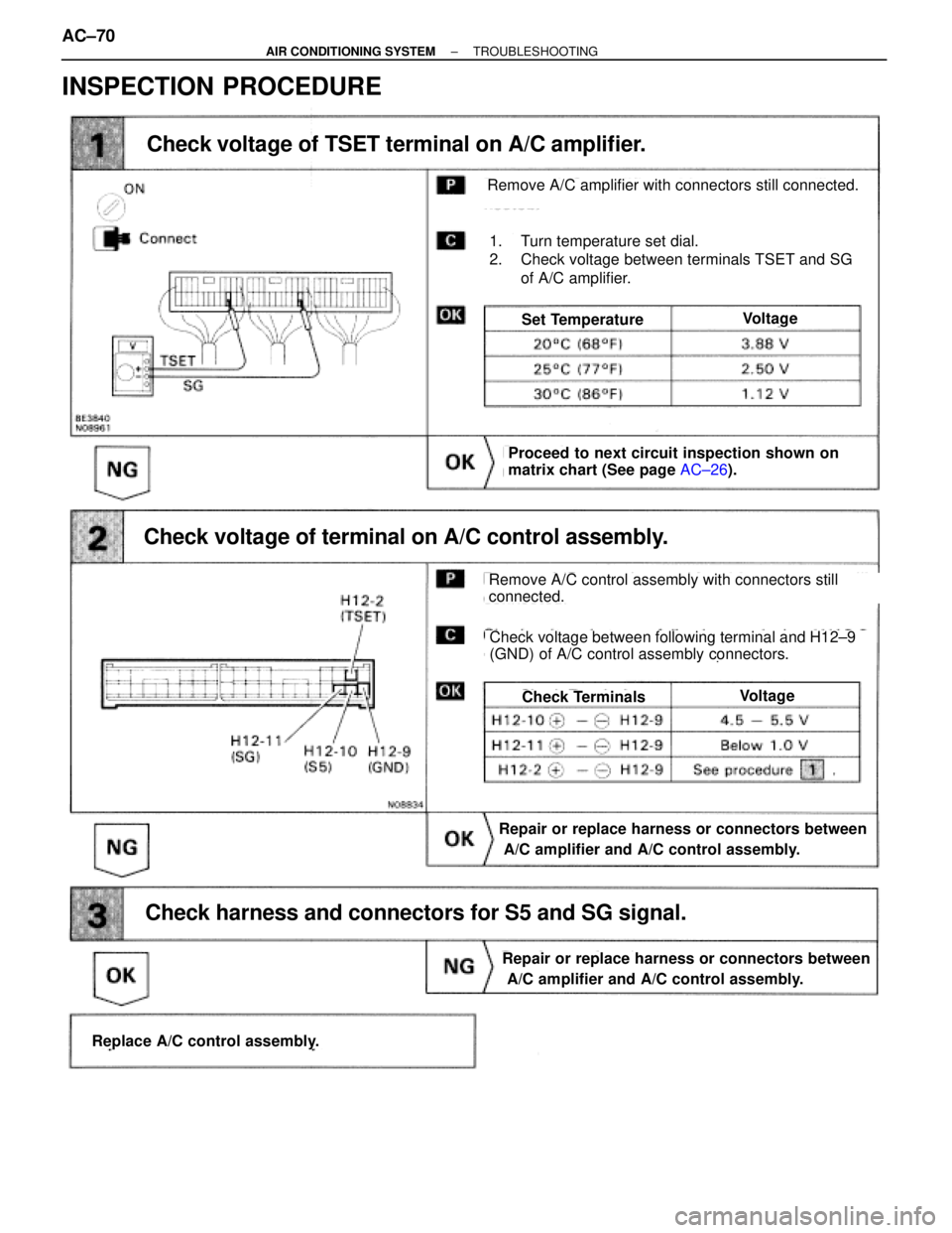
INSPECTION PROCEDURE
Check voltage of TSET terminal on A/C amplifier.
Check voltage of terminal on A/C control assembly.
Check harness and connectors for S5 and SG signal.
Proceed to next circuit inspection shown on
matrix chart (See page AC±26).
Replace A/C control assembly.
Repair or replace harness or connectors between
A/C amplifier and A/C control assembly.
Repair or replace harness or connectors between
A/C amplifier and A/C control assembly.
VoltageCheck Terminals
VoltageSet Temperature
1. Turn temperature set dial.
2. Check voltage between terminals TSET and SG
of A/C amplifier.
Remove A/C amplifier with connectors still connected.
Remove A/C control assembly with connectors still
connected.
Check voltage between following terminal and H12±9
(GND) of A/C control assembly connectors.
AC±70± AIR CONDITIONING SYSTEMTROUBLESHOOTING
Trending: transmission fluid, inflation pressure, brake fluid, trip computer, heating, coolant reservoir, steering
