check engine TOYOTA SUPRA 1995 Service Manual PDF
[x] Cancel search | Manufacturer: TOYOTA, Model Year: 1995, Model line: SUPRA, Model: TOYOTA SUPRA 1995Pages: 2543, PDF Size: 53.25 MB
Page 751 of 2543
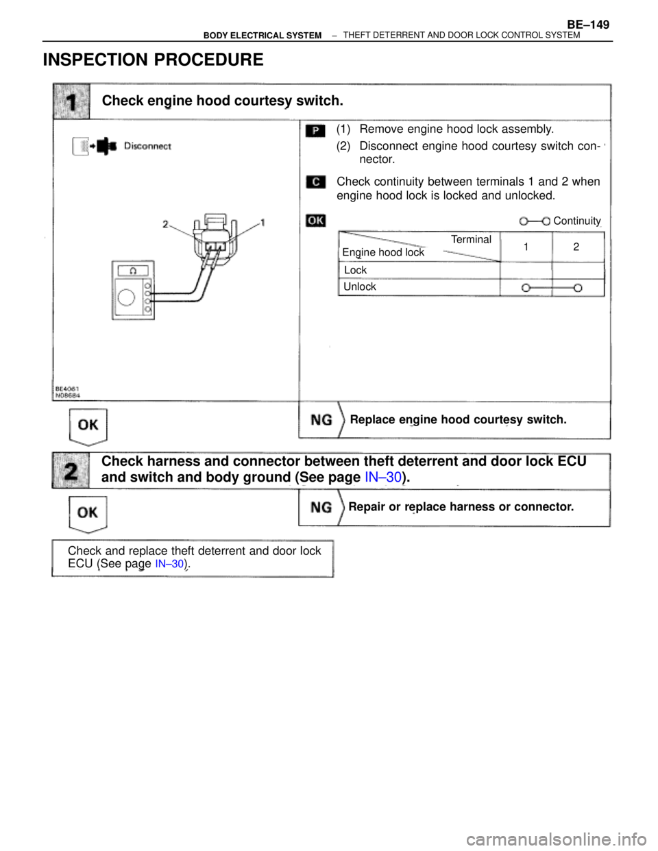
INSPECTION PROCEDURE
(See page IN±30).
(1) Remove engine hood lock assembly.
(2) Disconnect engine hood courtesy switch con-
nector.
Check continuity between terminals 1 and 2 when
engine hood lock is locked and unlocked.
Check and replace theft deterrent and door lock
ECU (See page
IN±30).
Check engine hood courtesy switch.
Engine hood lock
Lock
Unlock
Terminal
Continuity
12
Repair or replace harness or connector.
Replace engine hood courtesy switch.
Check harness and connector between theft deterrent and door lock ECU
and switch and body ground (See page IN±30).
± BODY ELECTRICAL SYSTEMBE±149THEFT DETERRENT AND DOOR LOCK CONTROL SYSTEM
Page 771 of 2543
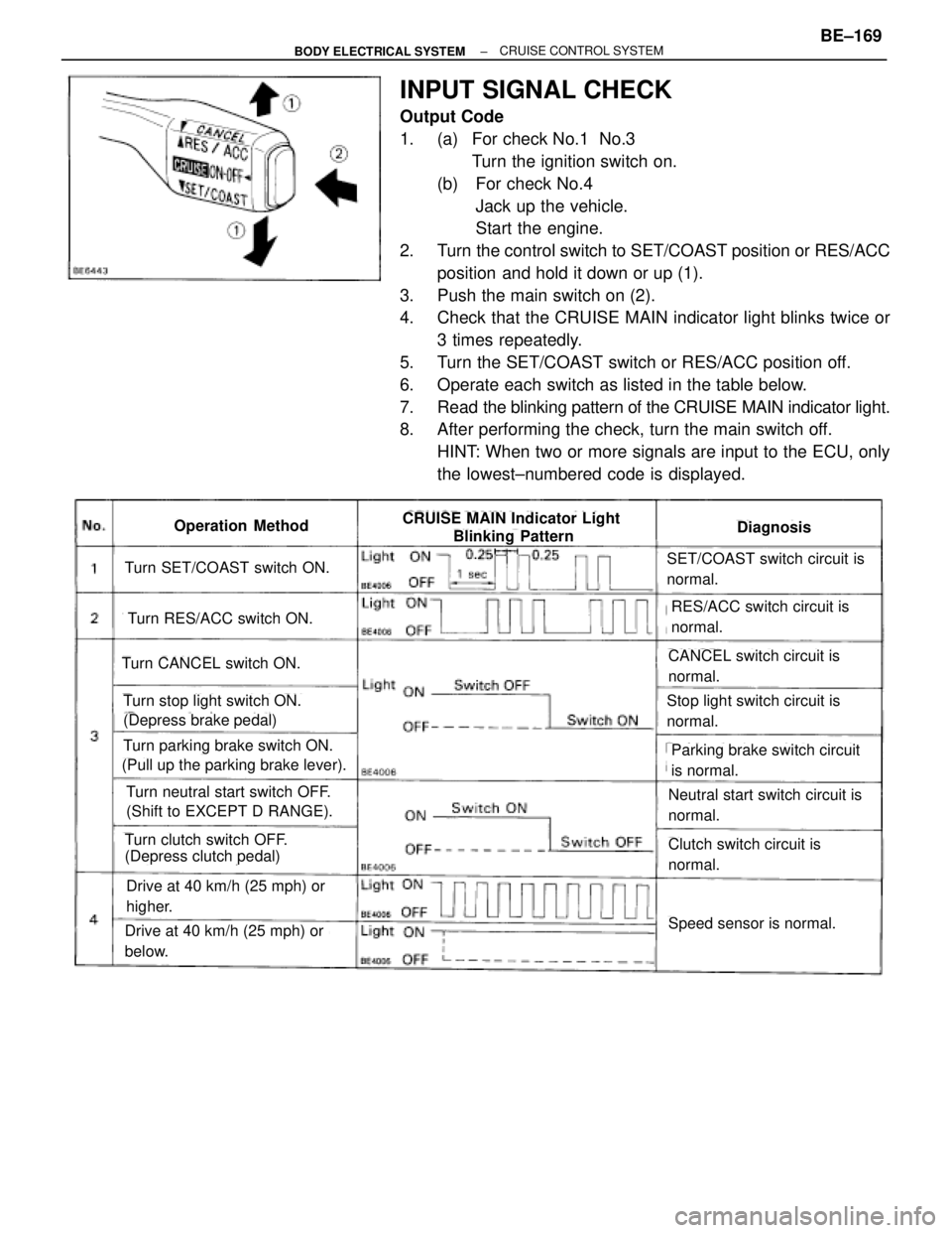
INPUT SIGNAL CHECK
Output Code
1. (a) For check No.1 No.3
Turn the ignition switch on.
(b) For check No.4
Jack up the vehicle.
Start the engine.
2. Turn the control switch to SET/COAST position or RES/ACC
position and hold it down or up (1).
3. Push the main switch on (2).
4. Check that the CRUISE MAIN indicator light blinks twice or
3 times repeatedly.
5. Turn the SET/COAST switch or RES/ACC position off.
6. Operate each switch as listed in the table below.
7. Read the blinking pattern of the CRUISE MAIN indicator light.
8. After performing the check, turn the main switch off.
HINT: When two or more signals are input to the ECU, only
the lowest±numbered code is displayed.
Turn SET/COAST switch ON.
Turn RES/ACC switch ON.
Turn CANCEL switch ON.
Turn stop light switch ON.
(Depress brake pedal)
Turn parking brake switch ON.
(Pull up the parking brake lever).
Turn neutral start switch OFF.
(Shift to EXCEPT D RANGE).
Turn clutch switch OFF.
(Depress clutch pedal)
Drive at 40 km/h (25 mph) or
higher.
Drive at 40 km/h (25 mph) or
below.
SET/COAST switch circuit is
normal.
RES/ACC switch circuit is
normal.
CANCEL switch circuit is
normal.
Stop light switch circuit is
normal.
Parking brake switch circuit
is normal.
Neutral start switch circuit is
normal.
Clutch switch circuit is
normal.
Speed sensor is normal.
DiagnosisOperation MethodCRUISE MAIN Indicator Light
Blinking Pattern
± BODY ELECTRICAL SYSTEMBE±169CRUISE CONTROL SYSTEM
Page 789 of 2543
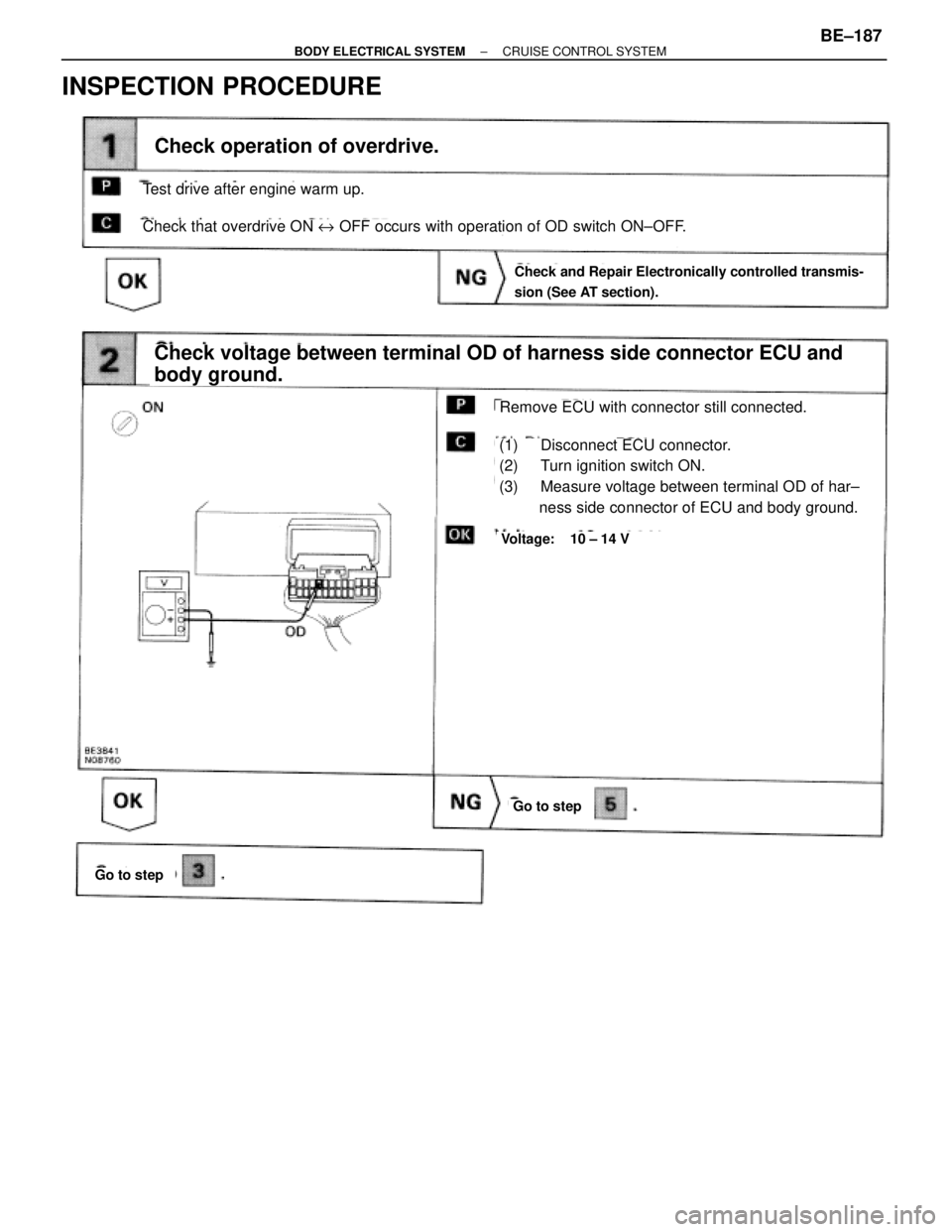
INSPECTION PROCEDURE
(1) Disconnect ECU connector.
(2) Turn ignition switch ON.
(3) Measure voltage between terminal OD of har±
ness side connector of ECU and body ground.
Check voltage between terminal OD of harness side connector ECU and
body ground.
Check operation of overdrive.
Remove ECU with connector still connected.
Check and Repair Electronically controlled transmis-
sion (See AT section).
Voltage: 10 ± 14 V
Go to step
Go to step
Test drive after engine warm up.
Check that overdrive ON e OFF occurs with operation of OD switch ON±OFF.
± BODY ELECTRICAL SYSTEMCRUISE CONTROL SYSTEMBE±187
Page 790 of 2543
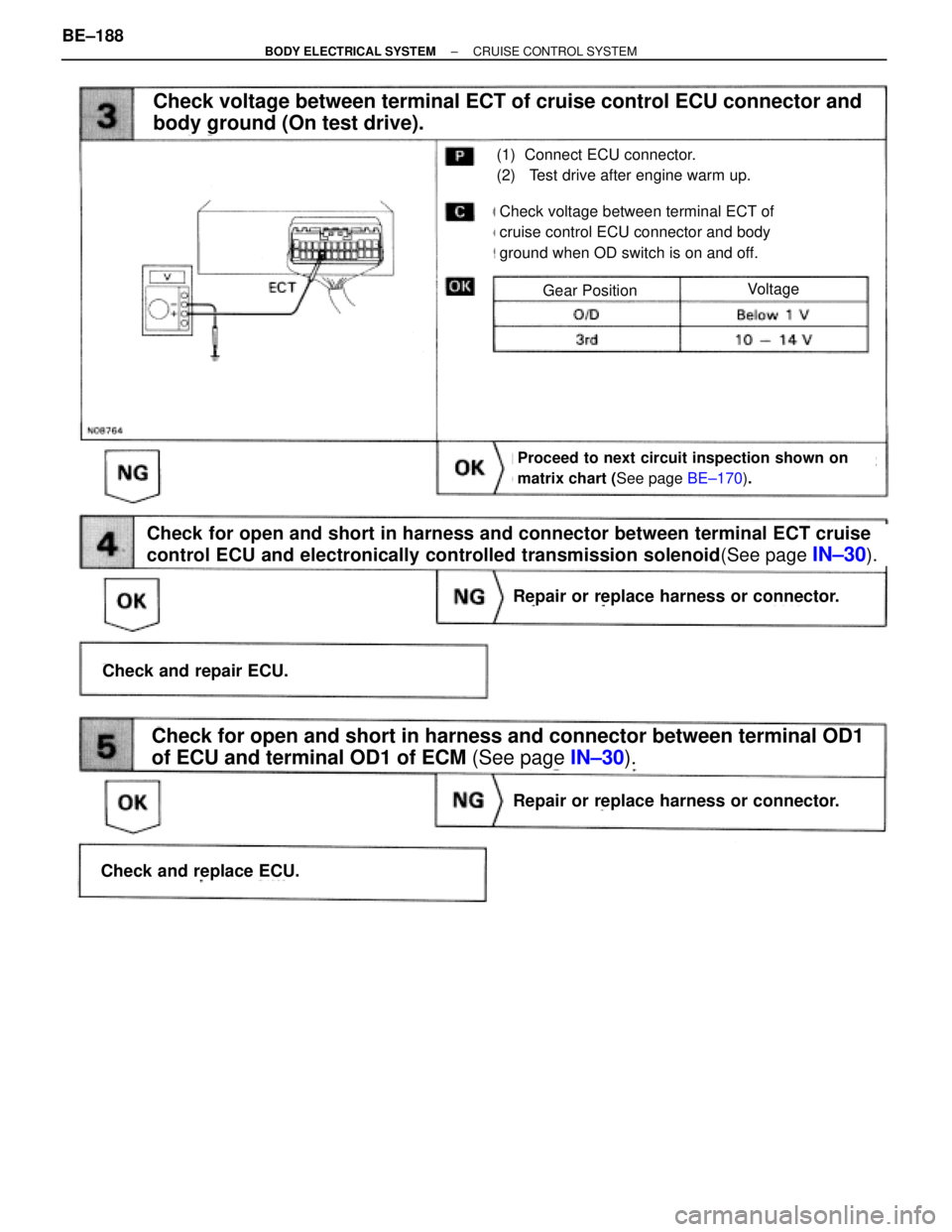
(See page IN±30).
Check voltage between terminal ECT of cruise control ECU connector and
body ground (On test drive).
(1) Connect ECU connector.
(2) Test drive after engine warm up.
Proceed to next circuit inspection shown on
matrix chart (See page BE±170).
Check voltage between terminal ECT of
cruise control ECU connector and body
ground when OD switch is on and off.
Repair or replace harness or connector.
Check and replace ECU.
Check and repair ECU.
Repair or replace harness or connector.
Check for open and short in harness and connector between terminal OD1
of ECU and terminal OD1 of ECM (See page IN±30).
Check for open and short in harness and connector between terminal ECT cruise
control ECU and electronically controlled transmission solenoid(See page
IN±30).
VoltageGear Position
BE±188± BODY ELECTRICAL SYSTEMCRUISE CONTROL SYSTEM
Page 792 of 2543
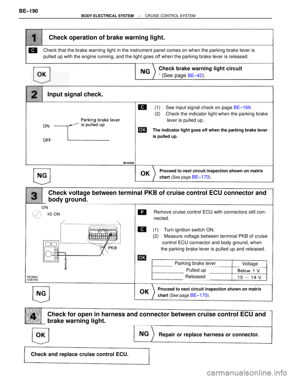
(See page BE±42).
BE±169.
Proceed to next circuit inspection shown on matrix
chart (See page
BE±170).
(1) See input signal check on page BE±169.
(2) Check the indicator light when the parking brake
lever is pulled up.
Check operation of brake warning light.
Check voltage between terminal PKB of cruise control ECU connector and
body ground.
(1) Turn ignition switch ON.
(2) Measure voltage between terminal PKB of cruise
control ECU connector and body ground, when
the parking brake lever is pulled up and released.
Remove cruise control ECU with connectors still con-
nected.
Input signal check.
The indicator light goes off when the parking brake lever
is pulled up.
Check that the brake warning light in the instrument panel comes on when the parking brake lever is
pulled up with the engine running, and the light goes off when the parking brake lever is released.
Check brake warning light circuit
Parking brake lever
Proceed to next circuit inspection shown on matrix
chart (See page
BE±170).
Voltage
Pulled up
Released
Check for open in harness and connector between cruise control ECU and
brake warning light.
Repair or replace harness or connector.
Check and replace cruise control ECU. BE±190
± BODY ELECTRICAL SYSTEMCRUISE CONTROL SYSTEM
Page 794 of 2543
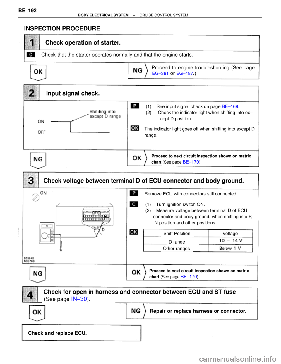
INSPECTION PROCEDURE
Check that the starter operates normally and that the engine starts.
EG±381 or EG±487.)
(See page IN±30).
on page BE±169.
Proceed to next circuit inspection shown on matrix
chart (See page
BE±170).
(1) See input signal check on page BE±169.
(2) Check the indicator light when shifting into ex±
cept D position.
Check operation of starter.
Check voltage between terminal D of ECU connector and body ground.
(1) Turn ignition switch ON.
(2) Measure voltage between terminal D of ECU
connector and body ground, when shifting into P,
N position and other positions.
Remove ECU with connectors still connected.
Input signal check.
The indicator light goes off when shifting into except D
range.
Proceed to engine troubleshooting (See page
Proceed to next circuit inspection shown on matrix
chart (See page
BE±170).
VoltageShift Position
D range
Other ranges
Check for open in harness and connector between ECU and ST fuse
Repair or replace harness or connector.
Check and replace ECU. BE±192
± BODY ELECTRICAL SYSTEMCRUISE CONTROL SYSTEM
Page 875 of 2543
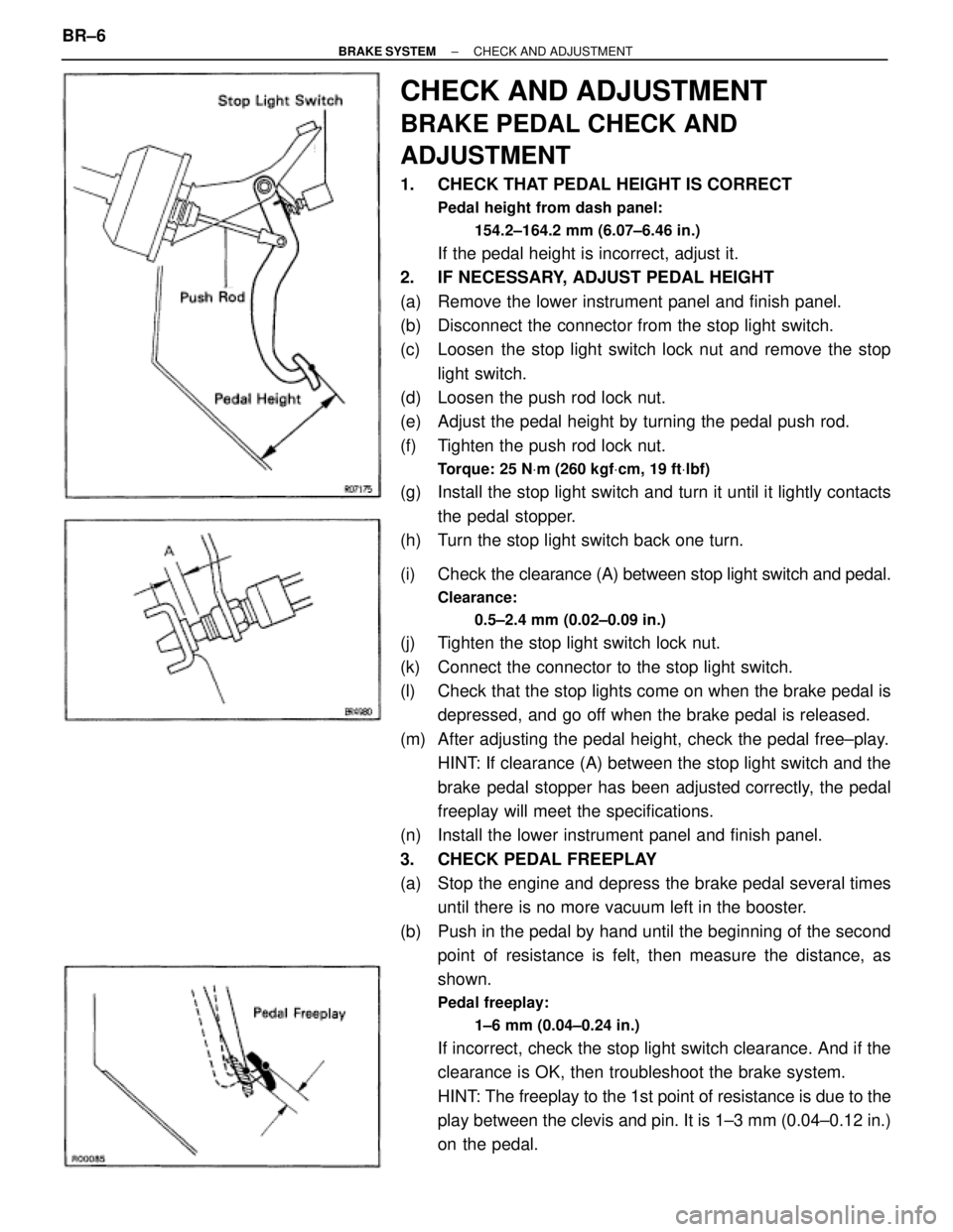
CHECK AND ADJUSTMENT
BRAKE PEDAL CHECK AND
ADJUSTMENT
1. CHECK THAT PEDAL HEIGHT IS CORRECT
Pedal height from dash panel:
154.2±164.2 mm (6.07±6.46 in.)
If the pedal height is incorrect, adjust it.
2. IF NECESSARY, ADJUST PEDAL HEIGHT
(a) Remove the lower instrument panel and finish panel.
(b) Disconnect the connector from the stop light switch.
(c) Loosen the stop light switch lock nut and remove the stop
light switch.
(d) Loosen the push rod lock nut.
(e) Adjust the pedal height by turning the pedal push rod.
(f) Tighten the push rod lock nut.
Torque: 25 NVm (260 kgfVcm, 19 ftVlbf)
(g) Install the stop light switch and turn it until it lightly contacts
the pedal stopper.
(h) Turn the stop light switch back one turn.
(i) Check the clearance (A) between stop light switch and pedal.
Clearance:
0.5±2.4 mm (0.02±0.09 in.)
(j) Tighten the stop light switch lock nut.
(k) Connect the connector to the stop light switch.
(l) Check that the stop lights come on when the brake pedal is
depressed, and go off when the brake pedal is released.
(m) After adjusting the pedal height, check the pedal free±play.
HINT: If clearance (A) between the stop light switch and the
brake pedal stopper has been adjusted correctly, the pedal
freeplay will meet the specifications.
(n) Install the lower instrument panel and finish panel.
3. CHECK PEDAL FREEPLAY
(a) Stop the engine and depress the brake pedal several times
until there is no more vacuum left in the booster.
(b) Push in the pedal by hand until the beginning of the second
point of resistance is felt, then measure the distance, as
shown.
Pedal freeplay:
1±6 mm (0.04±0.24 in.)
If incorrect, check the stop light switch clearance. And if the
clearance is OK, then troubleshoot the brake system.
HINT: The freeplay to the 1st point of resistance is due to the
play between the clevis and pin. It is 1±3 mm (0.04±0.12 in.)
on the pedal. BR±6
± BRAKE SYSTEMCHECK AND ADJUSTMENT
Page 876 of 2543
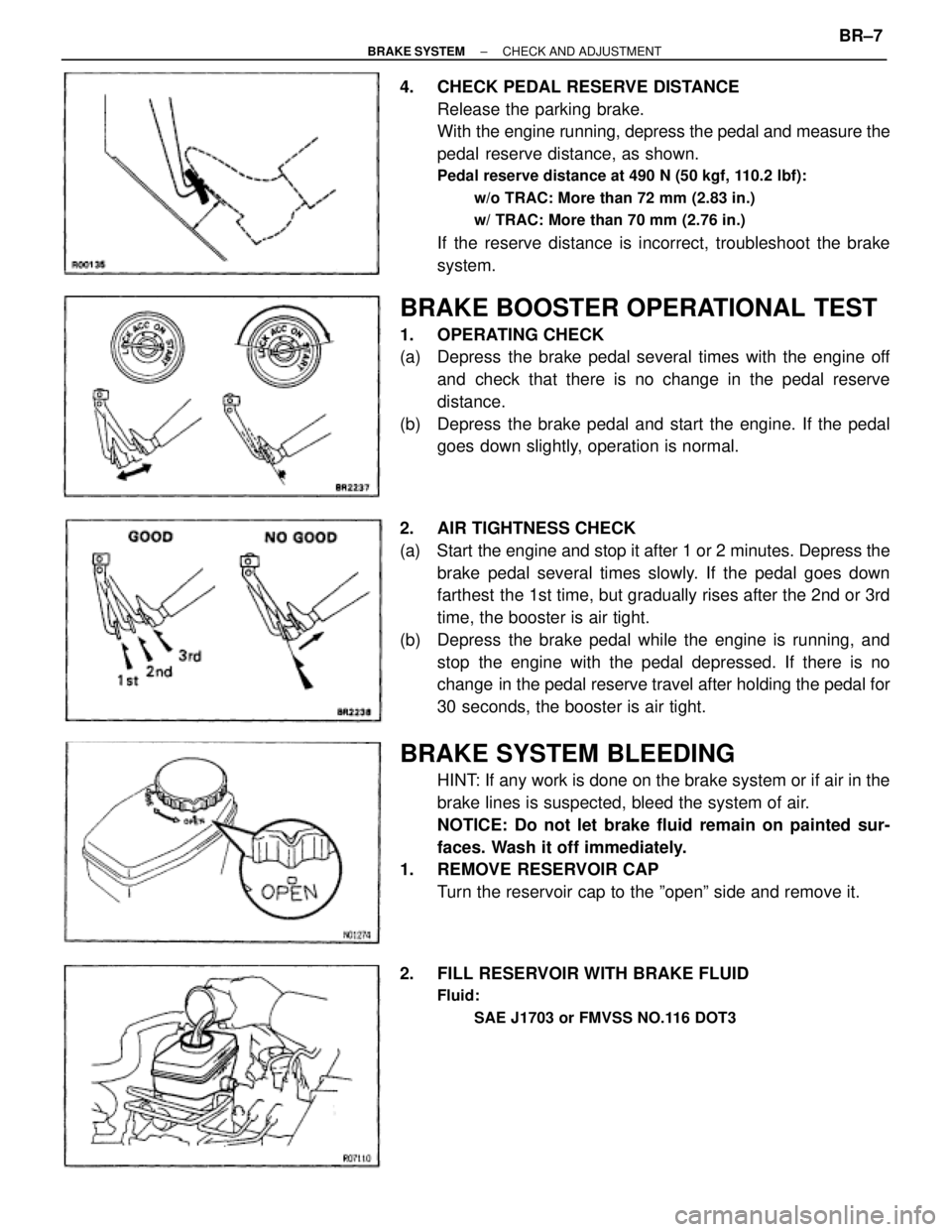
4. CHECK PEDAL RESERVE DISTANCE
Release the parking brake.
With the engine running, depress the pedal and measure the
pedal reserve distance, as shown.
Pedal reserve distance at 490 N (50 kgf, 110.2 lbf):
w/o TRAC: More than 72 mm (2.83 in.)
w/ TRAC: More than 70 mm (2.76 in.)
If the reserve distance is incorrect, troubleshoot the brake
system.
BRAKE BOOSTER OPERATIONAL TEST
1. OPERATING CHECK
(a) Depress the brake pedal several times with the engine off
and check that there is no change in the pedal reserve
distance.
(b) Depress the brake pedal and start the engine. If the pedal
goes down slightly, operation is normal.
2. AIR TIGHTNESS CHECK
(a) Start the engine and stop it after 1 or 2 minutes. Depress the
brake pedal several times slowly. If the pedal goes down
farthest the 1st time, but gradually rises after the 2nd or 3rd
time, the booster is air tight.
(b) Depress the brake pedal while the engine is running, and
stop the engine with the pedal depressed. If there is no
change in the pedal reserve travel after holding the pedal for
30 seconds, the booster is air tight.
BRAKE SYSTEM BLEEDING
HINT: If any work is done on the brake system or if air in the
brake lines is suspected, bleed the system of air.
NOTICE: Do not let brake fluid remain on painted sur-
faces. Wash it off immediately.
1. REMOVE RESERVOIR CAP
Turn the reservoir cap to the ºopenº side and remove it.
2. FILL RESERVOIR WITH BRAKE FLUID
Fluid:
SAE J1703 or FMVSS NO.116 DOT3
± BRAKE SYSTEMCHECK AND ADJUSTMENTBR±7
Page 878 of 2543
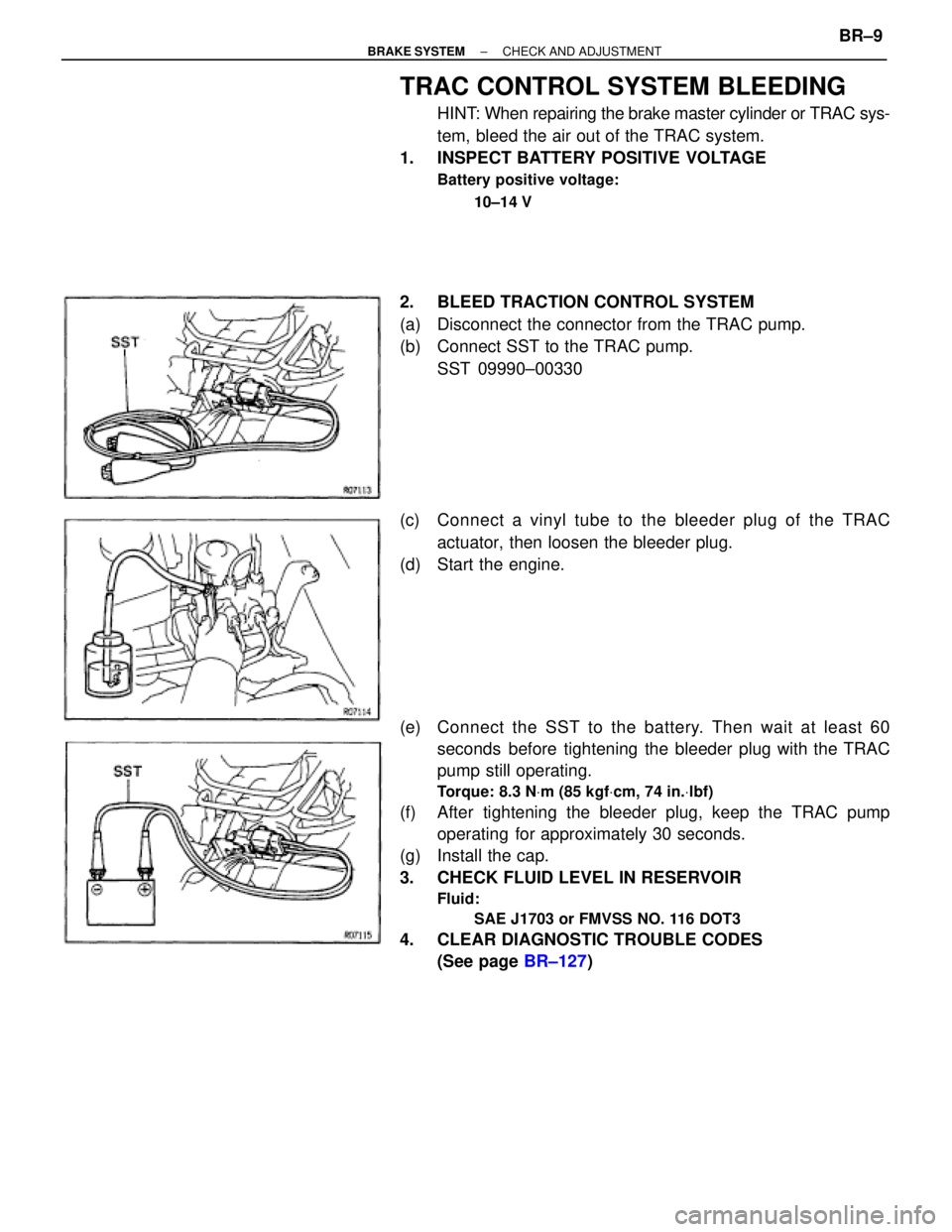
TRAC CONTROL SYSTEM BLEEDING
HINT: When repairing the brake master cylinder or TRAC sys-
tem, bleed the air out of the TRAC system.
1. INSPECT BATTERY POSITIVE VOLTAGE
Battery positive voltage:
10±14 V
2. BLEED TRACTION CONTROL SYSTEM
(a) Disconnect the connector from the TRAC pump.
(b) Connect SST to the TRAC pump.
SST 09990±00330
(c) Connect a vinyl tube to the bleeder plug of the TRAC
actuator, then loosen the bleeder plug.
(d) Start the engine.
(e) Connect the SST to the battery. Then wait at least 60
seconds before tightening the bleeder plug with the TRAC
pump still operating.
Torque: 8.3 NVm (85 kgfVcm, 74 in.Vlbf)
(f) After tightening the bleeder plug, keep the TRAC pump
operating for approximately 30 seconds.
(g) Install the cap.
3. CHECK FLUID LEVEL IN RESERVOIR
Fluid:
SAE J1703 or FMVSS NO. 116 DOT3
4. CLEAR DIAGNOSTIC TROUBLE CODES
(See page BR±127)
± BRAKE SYSTEMCHECK AND ADJUSTMENTBR±9
Page 915 of 2543
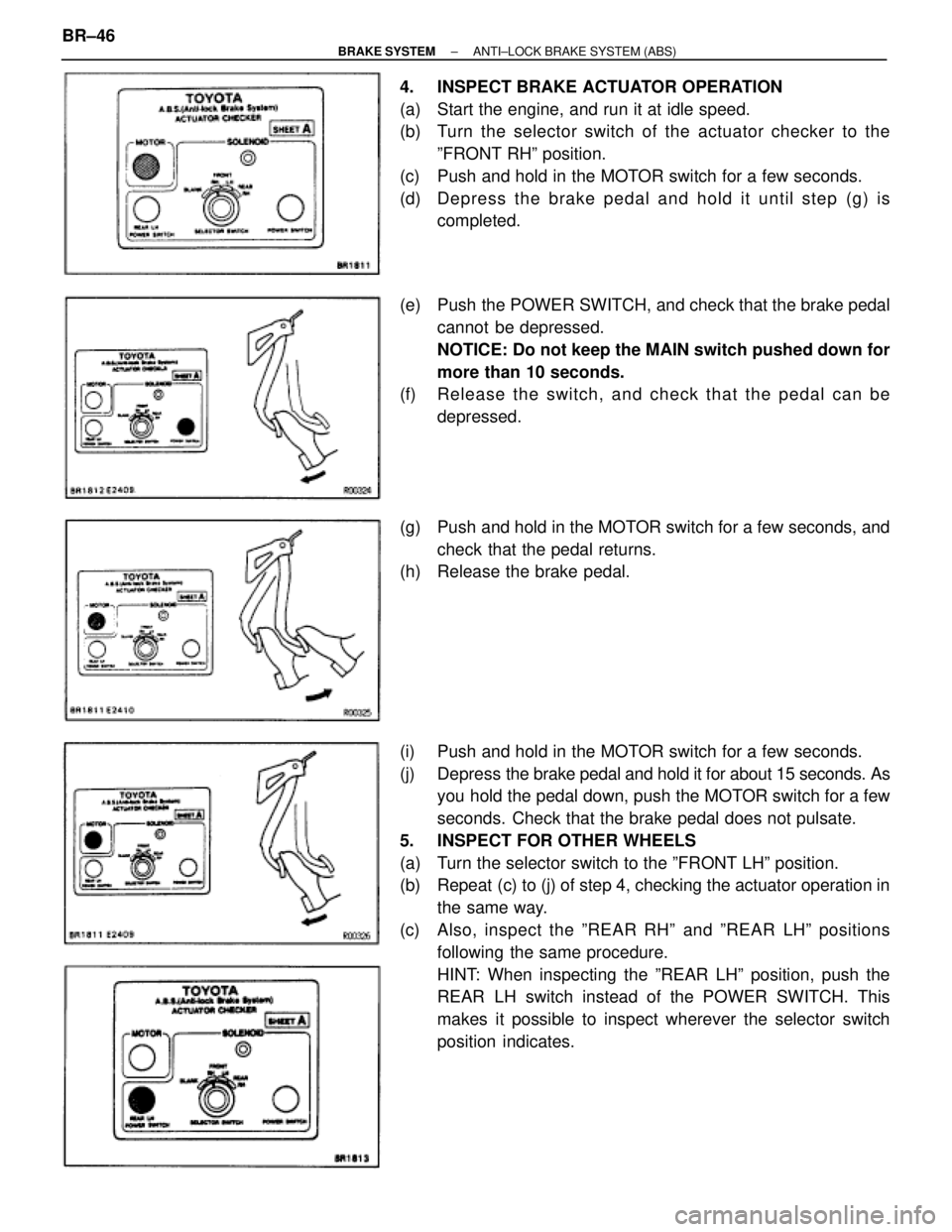
4. INSPECT BRAKE ACTUATOR OPERATION
(a) Start the engine, and run it at idle speed.
(b) Turn the selector switch of the actuator checker to the
ºFRONT RHº position.
(c) Push and hold in the MOTOR switch for a few seconds.
(d) De p re ss th e bra ke pedal and hold it until step (g) is
completed.
(e) Push the POWER SWITCH, and check that the brake pedal
cannot be depressed.
NOTICE: Do not keep the MAIN switch pushed down for
more than 10 seconds.
(f) Re le a se th e switch , an d ch e ck th a t th e pedal can be
depressed.
(g) Push and hold in the MOTOR switch for a few seconds, and
check that the pedal returns.
(h) Release the brake pedal.
(i) Push and hold in the MOTOR switch for a few seconds.
(j) Depress the brake pedal and hold it for about 15 seconds. As
you hold the pedal down, push the MOTOR switch for a few
seconds. Check that the brake pedal does not pulsate.
5. INSPECT FOR OTHER WHEELS
(a) Turn the selector switch to the ºFRONT LHº position.
(b) Repeat (c) to (j) of step 4, checking the actuator operation in
the same way.
(c) Also, inspect the ºREAR RHº and ºREAR LHº positions
following the same procedure.
HINT: When inspecting the ºREAR LHº position, push the
REAR LH switch instead of the POWER SWITCH. This
makes it possible to inspect wherever the selector switch
position indicates. BR±46
± BRAKE SYSTEMANTI±LOCK BRAKE SYSTEM (ABS)