TOYOTA SUPRA 1995 Service Repair Manual
SUPRA 1995
TOYOTA
TOYOTA
https://www.carmanualsonline.info/img/14/57468/w960_57468-0.png
TOYOTA SUPRA 1995 Service Repair Manual
Trending: engine overheat, power steering fluid, ECU, transmission fluid, headlight aiming, reset, oil and filter replacement
Page 741 of 2543
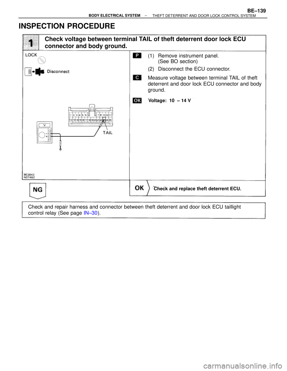
INSPECTION PROCEDURE
(See page IN±30).
(1) Remove instrument panel.
(See BO section)
(2) Disconnect the ECU connector.
Check and replace theft deterrent ECU.
Measure voltage between terminal TAIL of theft
deterrent and door lock ECU connector and body
ground.
Voltage: 10 ± 14 V
Check and repair harness and connector between theft deterrent and door lock ECU taillight
control relay (See page IN±30).
Check voltage between terminal TAIL of theft deterrent door lock ECU
connector and body ground.
± BODY ELECTRICAL SYSTEMBE±139THEFT DETERRENT AND DOOR LOCK CONTROL SYSTEM
Page 742 of 2543
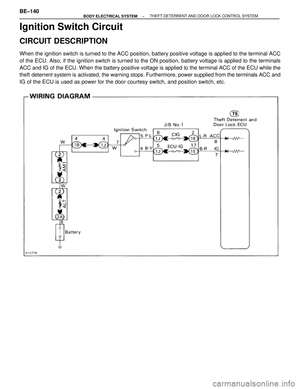
Ignition Switch Circuit
CIRCUIT DESCRIPTION
When the ignition switch is turned to the ACC position, battery positive voltage is applied to the terminal ACC
of the ECU. Also, if the ignition switch is turned to the ON position, battery voltage is applied to the terminals
ACC and IG of the ECU. When the battery positive voltage is applied to the terminal ACC of the ECU while the
theft deterrent system is activated, the warning stops. Furthermore, power supplied from the terminals ACC and
IG of the ECU is used as power for the door courtesy switch, and position switch, etc.
BE±140± BODY ELECTRICAL SYSTEMTHEFT DETERRENT AND DOOR LOCK CONTROL SYSTEM
Page 743 of 2543
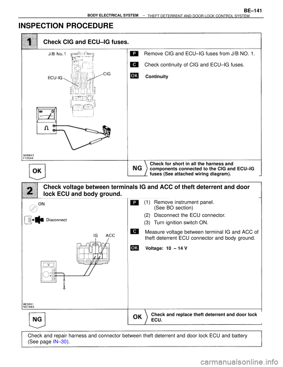
(See page IN±30).
Check for short in all the harness and
components connected to the CIG and ECU±IG
fuses (See attached wiring diagram).
(1) Remove instrument panel.
(See BO section)
(2) Disconnect the ECU connector.
(3) Turn ignition switch ON.
Check and replace theft deterrent and door lock
ECU.
Measure voltage between terminal IG and ACC of
theft deterrent ECU connector and body ground.
Voltage: 10 ± 14 V
Check and repair harness and connector between theft deterrent and door lock ECU and battery
(See page IN±30).
Check voltage between terminals IG and ACC of theft deterrent and door
lock ECU and body ground.
Continuity
Remove CIG and ECU±IG fuses from J/B NO. 1.
Check continuity of CIG and ECU±IG fuses.
Check CIG and ECU±IG fuses.
INSPECTION PROCEDURE
± BODY ELECTRICAL SYSTEMBE±141
THEFT DETERRENT AND DOOR LOCK CONTROL SYSTEM
Page 744 of 2543
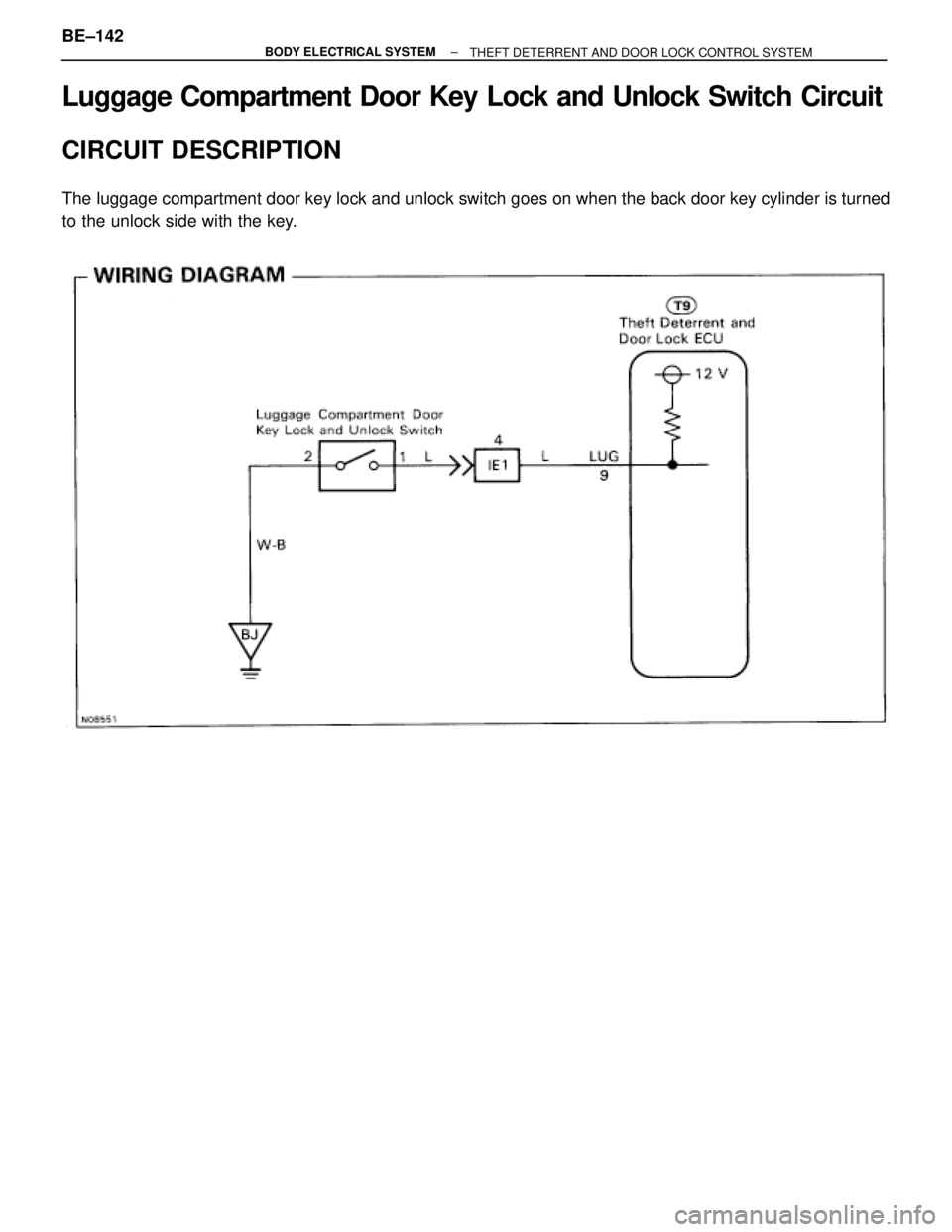
Luggage Compartment Door Key Lock and Unlock Switch Circuit
CIRCUIT DESCRIPTION
The luggage compartment door key lock and unlock switch goes on when the back door key cylinder is turned
to the unlock side with the key.
BE±142± BODY ELECTRICAL SYSTEM
THEFT DETERRENT AND DOOR LOCK CONTROL SYSTEM
Page 745 of 2543
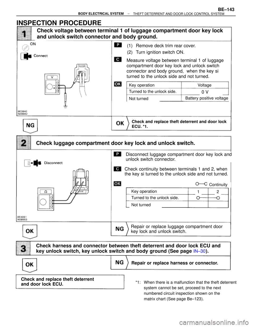
(See page IN±30).
(1) Remove deck trim rear cover.
(2) Turn ignition switch ON.
Repair or replace luggage compartment door
key lock and unlock switch.
Measure voltage between terminal 1 of luggage
compartment door key lock and unlock switch
connector and body ground, when the key si
turned to the unlock side and not turned.
Check and replace theft deterrent and door lock
ECU. *1.
Check harness and connector between theft deterrent and door lock ECU and
key unlock switch, key unlock switch and body ground (See page
IN±30).
Check voltage between terminal 1 of luggage compartment door key lock
and unlock switch connector and body ground.
Key operation
Turned to the unlock side.
Not turned
Voltage
0 V
Battery positive voltage
Check luggage compartment door key lock and unlock switch.
Key operation
Turned to the unlock side.
Not turned
Disconnect luggage compartment door key lock and
unlock switch connector.
Check continuity between terminals 1 and 2, when
the key si turned to the unlock side and not turned.
Continuity
12
Repair or replace harness or connector.
Check and replace theft deterrent
and door lock ECU.
INSPECTION PROCEDURE
*1: When there is a malfunction that the theft deterrent
system cannot be set, proceed to the next
numbered circuit inspection shown on the
matrix chart (See page Be±123).
± BODY ELECTRICAL SYSTEMBE±143THEFT DETERRENT AND DOOR LOCK CONTROL SYSTEM
Page 746 of 2543
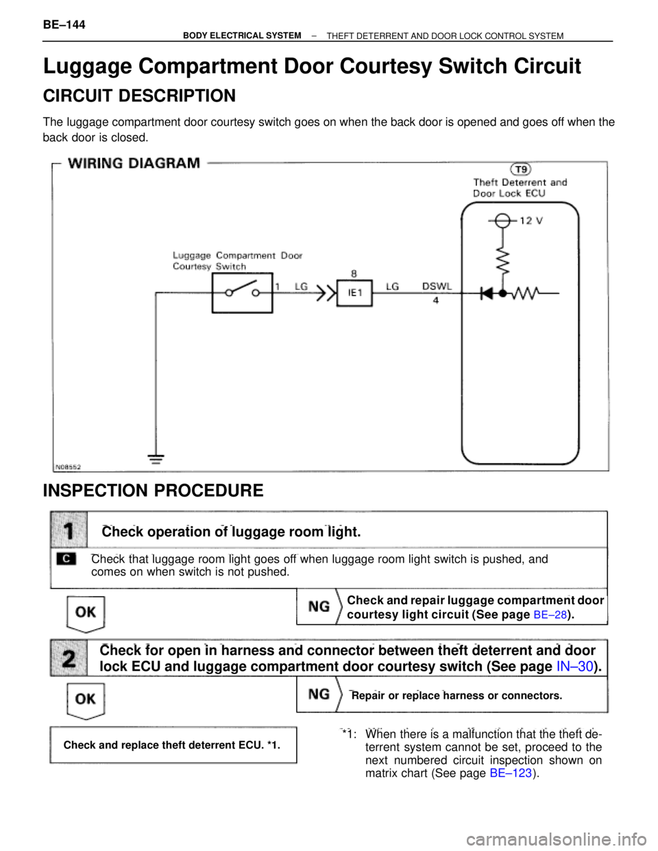
Luggage Compartment Door Courtesy Switch Circuit
CIRCUIT DESCRIPTION
The luggage compartment door courtesy switch goes on when the back door is opened and goes off when the
back door is closed.
INSPECTION PROCEDURE
Check and repair luggage compartment door
courtesy light circuit (See page
BE±28).
(See page IN±30).
Check and replace theft deterrent ECU. *1.
Check operation of luggage room light.
Check that luggage room light goes off when luggage room light switch is pushed, and
comes on when switch is not pushed.
*1: When there is a malfunction that the theft de-
terrent system cannot be set, proceed to the
next numbered circuit inspection shown on
matrix chart (See page BE±123).
Check for open in harness and connector between theft deterrent and door
lock ECU and luggage compartment door courtesy switch (See page IN±30).
Repair or replace harness or connectors.
BE±144± BODY ELECTRICAL SYSTEM
THEFT DETERRENT AND DOOR LOCK CONTROL SYSTEM
Page 747 of 2543
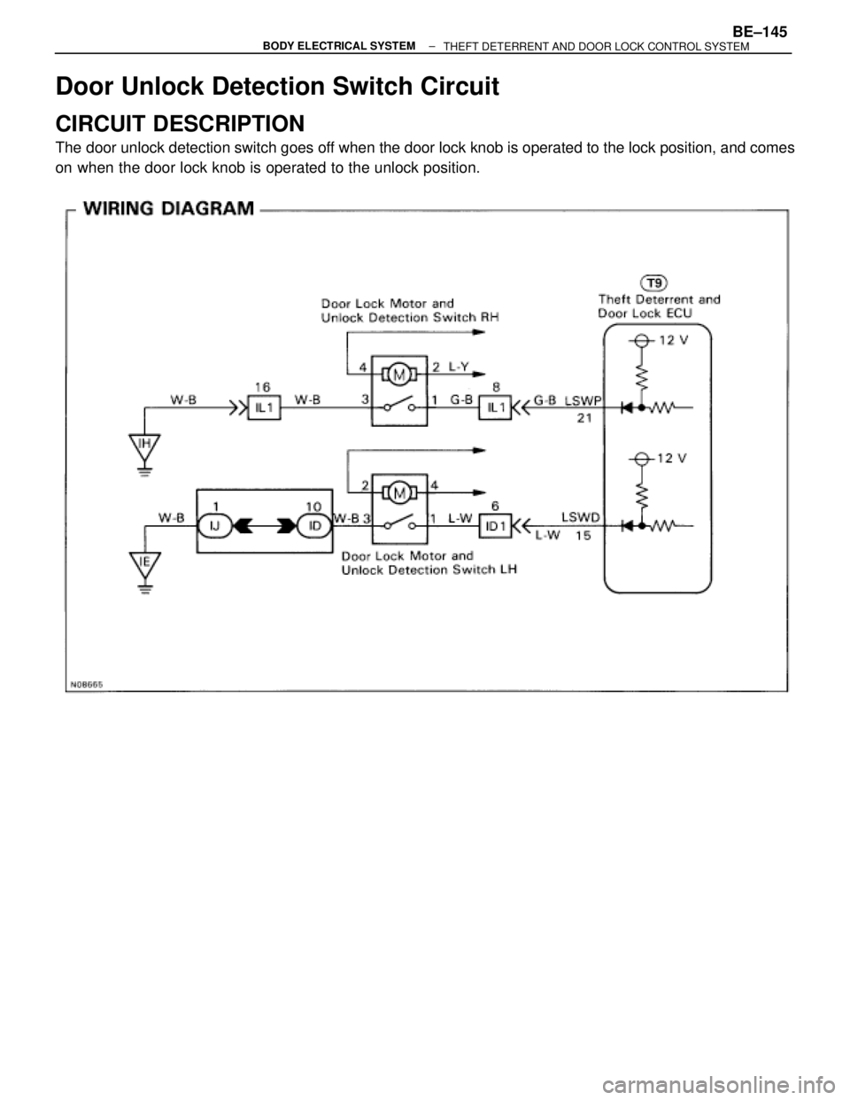
Door Unlock Detection Switch Circuit
CIRCUIT DESCRIPTION
The door unlock detection switch goes off when the door lock knob is operated to the lock position, and comes
on when the door lock knob is operated to the unlock position.
± BODY ELECTRICAL SYSTEMBE±145THEFT DETERRENT AND DOOR LOCK CONTROL SYSTEM
Page 748 of 2543
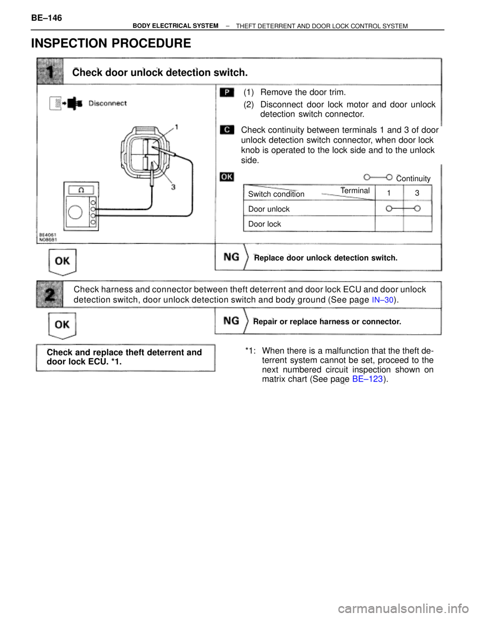
INSPECTION PROCEDURE
Check harness and connector between theft deterrent and door lock ECU and door unlock
detection switch, door unlock detection switch and body ground (See page
IN±30).
(1) Remove the door trim.
(2) Disconnect door lock motor and door unlock
detection switch connector.
Check continuity between terminals 1 and 3 of door
unlock detection switch connector, when door lock
knob is operated to the lock side and to the unlock
side.
Replace door unlock detection switch.
Check door unlock detection switch.
Switch condition
Door unlock
Door lock
Terminal
Continuity
13
Repair or replace harness or connector.
Check and replace theft deterrent and
door lock ECU. *1.*1: When there is a malfunction that the theft de-
terrent system cannot be set, proceed to the
next numbered circuit inspection shown on
matrix chart (See page BE±123). BE±146
± BODY ELECTRICAL SYSTEM
THEFT DETERRENT AND DOOR LOCK CONTROL SYSTEM
Page 749 of 2543
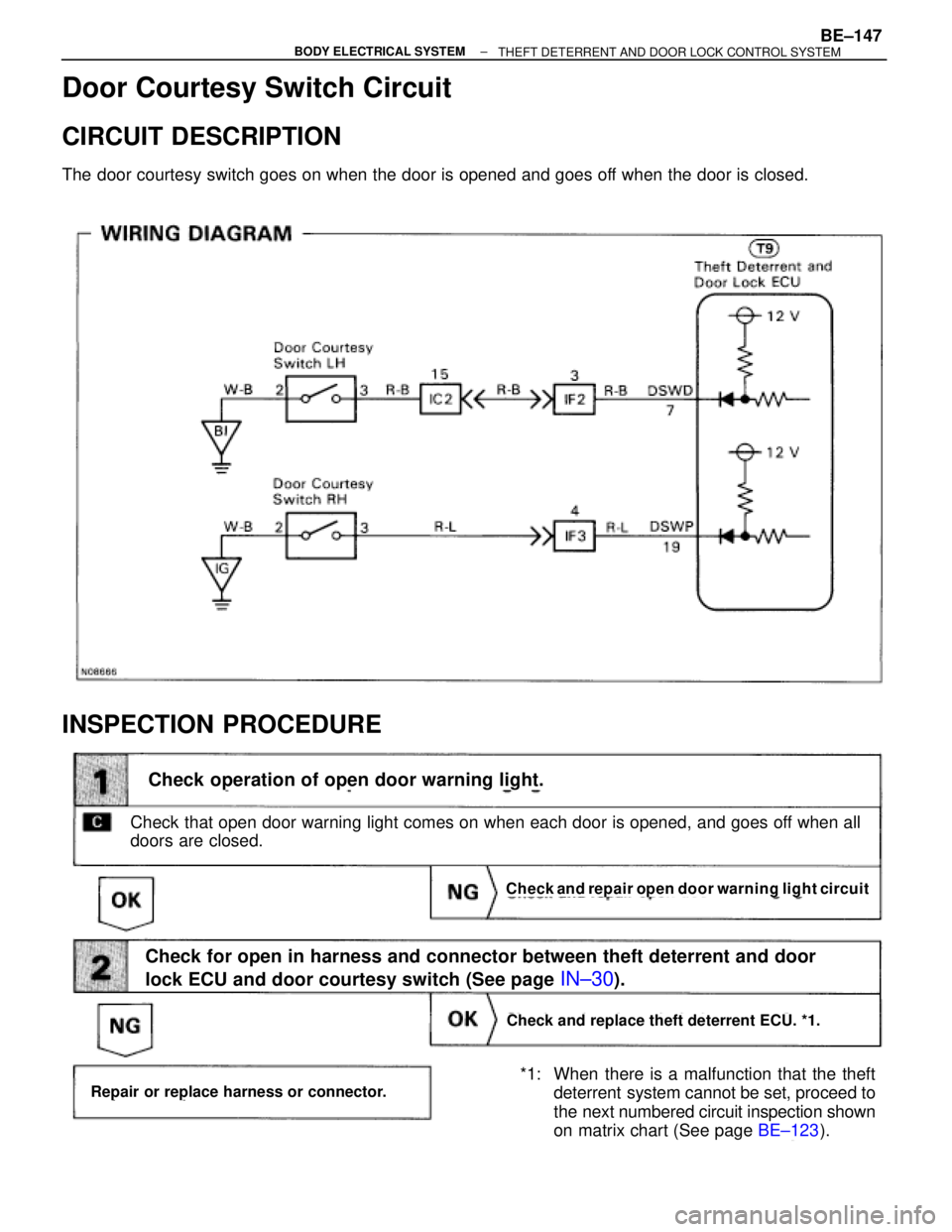
Door Courtesy Switch Circuit
CIRCUIT DESCRIPTION
The door courtesy switch goes on when the door is opened and goes off when the door is closed.
INSPECTION PROCEDURE
(See page BE±123).
Check and repair open door warning light circuit
Check and replace theft deterrent ECU. *1.
Check operation of open door warning light.
Check that open door warning light comes on when each door is opened, and goes off when all
doors are closed.
*1: When there is a malfunction that the theft
deterrent system cannot be set, proceed to
the next numbered circuit inspection shown
on matrix chart (See page BE±123).
Check for open in harness and connector between theft deterrent and door
lock ECU and door courtesy switch (See page
IN±30).
Repair or replace harness or connector.
± BODY ELECTRICAL SYSTEMBE±147THEFT DETERRENT AND DOOR LOCK CONTROL SYSTEM
Page 750 of 2543
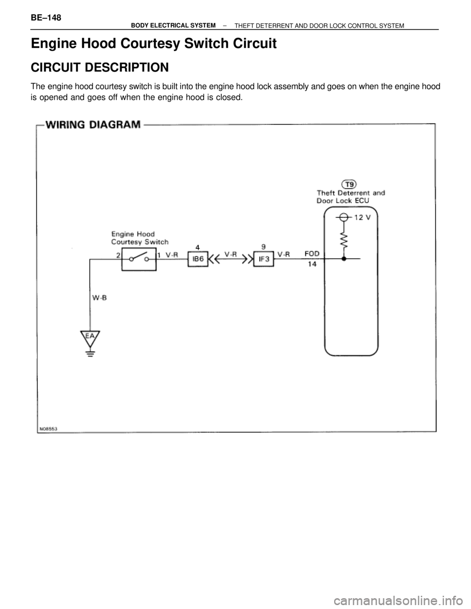
Engine Hood Courtesy Switch Circuit
CIRCUIT DESCRIPTION
The engine hood courtesy switch is built into the engine hood lock assembly and goes on when the engine hood
is opened and goes off when the engine hood is closed.
BE±148± BODY ELECTRICAL SYSTEM
THEFT DETERRENT AND DOOR LOCK CONTROL SYSTEM
Trending: weight, radio antenna, oil filter, brakes, spare wheel, oil dipstick, dimensions
