TOYOTA SUPRA 1995 Service Repair Manual
SUPRA 1995
TOYOTA
TOYOTA
https://www.carmanualsonline.info/img/14/57468/w960_57468-0.png
TOYOTA SUPRA 1995 Service Repair Manual
Trending: run flat, drain bolt, engine oil capacity, clutch, oil, phone, battery
Page 911 of 2543
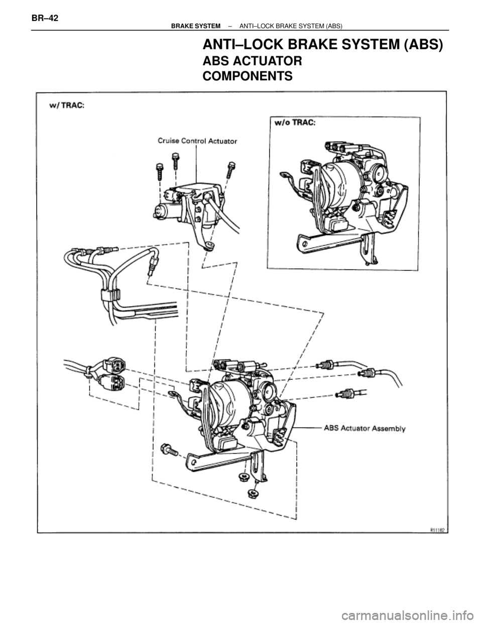
ANTI±LOCK BRAKE SYSTEM (ABS)
ABS ACTUATOR
COMPONENTS
BR±42± BRAKE SYSTEMANTI±LOCK BRAKE SYSTEM (ABS)
Page 912 of 2543
± BRAKE SYSTEMANTI±LOCK BRAKE SYSTEM (ABS)BR±43
Page 913 of 2543
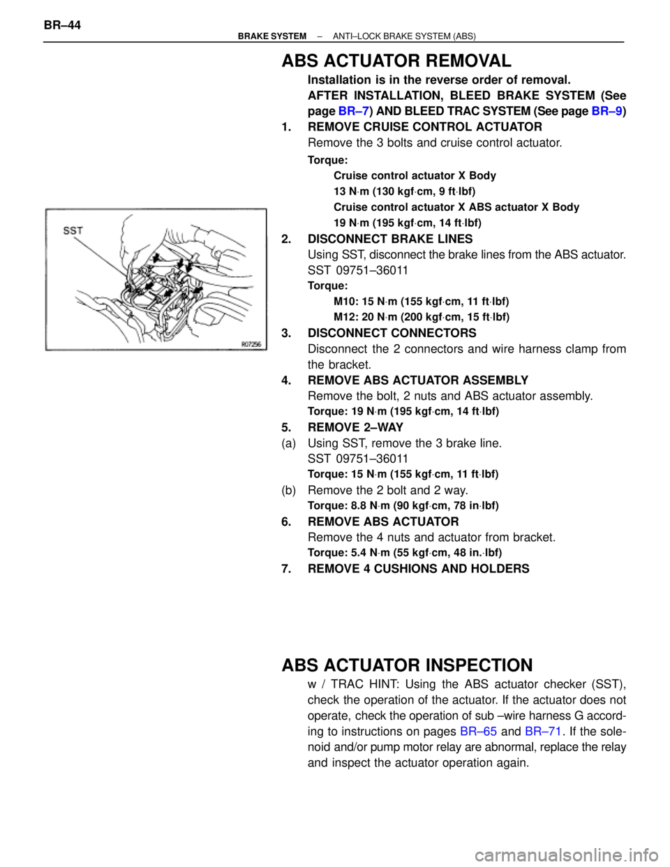
ABS ACTUATOR REMOVAL
Installation is in the reverse order of removal.
AFTER INSTALLATION, BLEED BRAKE SYSTEM (See
page BR±7) AND BLEED TRAC SYSTEM (See page BR±9)
1. REMOVE CRUISE CONTROL ACTUATOR
Remove the 3 bolts and cruise control actuator.
Torque:
Cruise control actuator X Body
13 NVm (130 kgfVcm, 9 ftVlbf)
Cruise control actuator X ABS actuator X Body
19 NVm (195 kgfVcm, 14 ftVlbf)
2. DISCONNECT BRAKE LINES
Using SST, disconnect the brake lines from the ABS actuator.
SST 09751±36011
Torque:
M10: 15 NVm (155 kgfVcm, 11 ftVlbf)
M12: 20 NVm (200 kgfVcm, 15 ftVlbf)
3. DISCONNECT CONNECTORS
Disconnect the 2 connectors and wire harness clamp from
the bracket.
4. REMOVE ABS ACTUATOR ASSEMBLY
Remove the bolt, 2 nuts and ABS actuator assembly.
Torque: 19 NVm (195 kgfVcm, 14 ftVlbf)
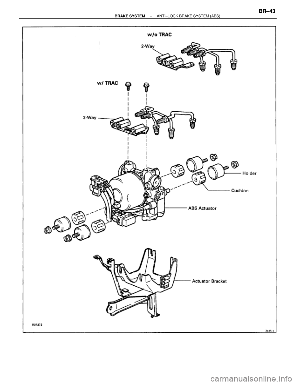
5. REMOVE 2±WAY
(a) Using SST, remove the 3 brake line.
SST 09751±36011
Torque: 15 NVm (155 kgfVcm, 11 ftVlbf)
(b) Remove the 2 bolt and 2 way.
Torque: 8.8 NVm (90 kgfVcm, 78 inVlbf)
6. REMOVE ABS ACTUATOR
Remove the 4 nuts and actuator from bracket.
Torque: 5.4 NVm (55 kgfVcm, 48 in.Vlbf)
7. REMOVE 4 CUSHIONS AND HOLDERS
ABS ACTUATOR INSPECTION
w / TRAC HINT: Using the ABS actuator checker (SST),
check the operation of the actuator. If the actuator does not
operate, check the operation of sub ±wire harness G accord-
ing to instructions on pages BR±65 and BR±71. If the sole-
noid and/or pump motor relay are abnormal, replace the relay
and inspect the actuator operation again. BR±44
± BRAKE SYSTEMANTI±LOCK BRAKE SYSTEM (ABS)
Page 914 of 2543
1. INSPECT BATTERY POSITIVE VOLTAGE
Battery positive voltage:
10±14 V
2. DISCONNECT CONNECTORS
(a) Disconnect the 2 connectors from the actuator.
(b) w/o TRAC:
Disconnect the 2 connectors from the control relay.
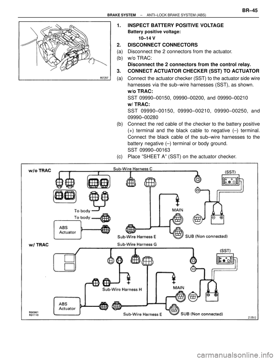
3. CONNECT ACTUATOR CHECKER (SST) TO ACTUATOR
(a) Connect the actuator checker (SST) to the actuator side wire
harnesses via the sub±wire harnesses (SST), as shown.
w/o TRAC:
SST 09990±00150, 09990±00200, and 09990±00210
w/ TRAC:
SST 09990±00150, 09990±00210, 09990±00250, and
09990±00280
(b) Connect the red cable of the checker to the battery positive
(+) terminal and the black cable to negative (±) terminal.
Connect the black cable of the sub±wire harnesses to the
battery negative (±) terminal or body ground.
SST 09990±00163
(c) Place ºSHEET Aº (SST) on the actuator checker.
± BRAKE SYSTEMANTI±LOCK BRAKE SYSTEM (ABS)BR±45
Page 915 of 2543
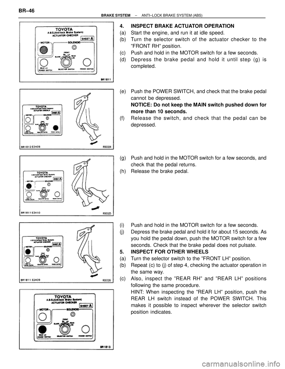
4. INSPECT BRAKE ACTUATOR OPERATION
(a) Start the engine, and run it at idle speed.
(b) Turn the selector switch of the actuator checker to the
ºFRONT RHº position.
(c) Push and hold in the MOTOR switch for a few seconds.
(d) De p re ss th e bra ke pedal and hold it until step (g) is
completed.
(e) Push the POWER SWITCH, and check that the brake pedal
cannot be depressed.
NOTICE: Do not keep the MAIN switch pushed down for
more than 10 seconds.
(f) Re le a se th e switch , an d ch e ck th a t th e pedal can be
depressed.
(g) Push and hold in the MOTOR switch for a few seconds, and
check that the pedal returns.
(h) Release the brake pedal.
(i) Push and hold in the MOTOR switch for a few seconds.
(j) Depress the brake pedal and hold it for about 15 seconds. As
you hold the pedal down, push the MOTOR switch for a few
seconds. Check that the brake pedal does not pulsate.
5. INSPECT FOR OTHER WHEELS
(a) Turn the selector switch to the ºFRONT LHº position.
(b) Repeat (c) to (j) of step 4, checking the actuator operation in
the same way.
(c) Also, inspect the ºREAR RHº and ºREAR LHº positions
following the same procedure.
HINT: When inspecting the ºREAR LHº position, push the
REAR LH switch instead of the POWER SWITCH. This
makes it possible to inspect wherever the selector switch
position indicates. BR±46
± BRAKE SYSTEMANTI±LOCK BRAKE SYSTEM (ABS)
Page 916 of 2543
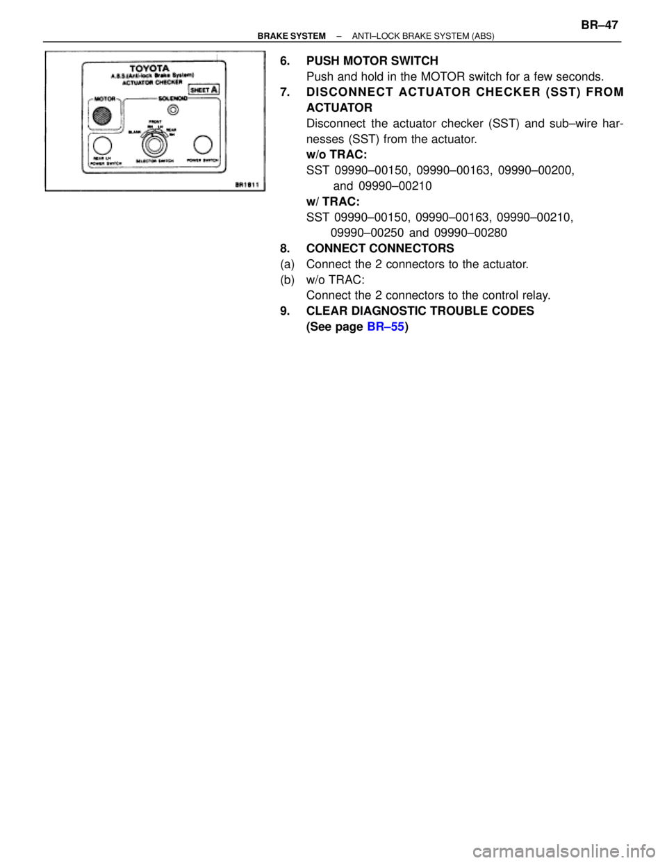
6. PUSH MOTOR SWITCH
Push and hold in the MOTOR switch for a few seconds.
7. DISCONNECT ACTUATOR CHECKER (SST) FROM
ACTUATOR
Disconnect the actuator checker (SST) and sub±wire har-
nesses (SST) from the actuator.
w/o TRAC:
SST 09990±00150, 09990±00163, 09990±00200,
and 09990±00210
w/ TRAC:
SST 09990±00150, 09990±00163, 09990±00210,
09990±00250 and 09990±00280
8. CONNECT CONNECTORS
(a) Connect the 2 connectors to the actuator.
(b) w/o TRAC:
Connect the 2 connectors to the control relay.
9. CLEAR DIAGNOSTIC TROUBLE CODES
(See page BR±55)
± BRAKE SYSTEMANTI±LOCK BRAKE SYSTEM (ABS)BR±47
Page 917 of 2543
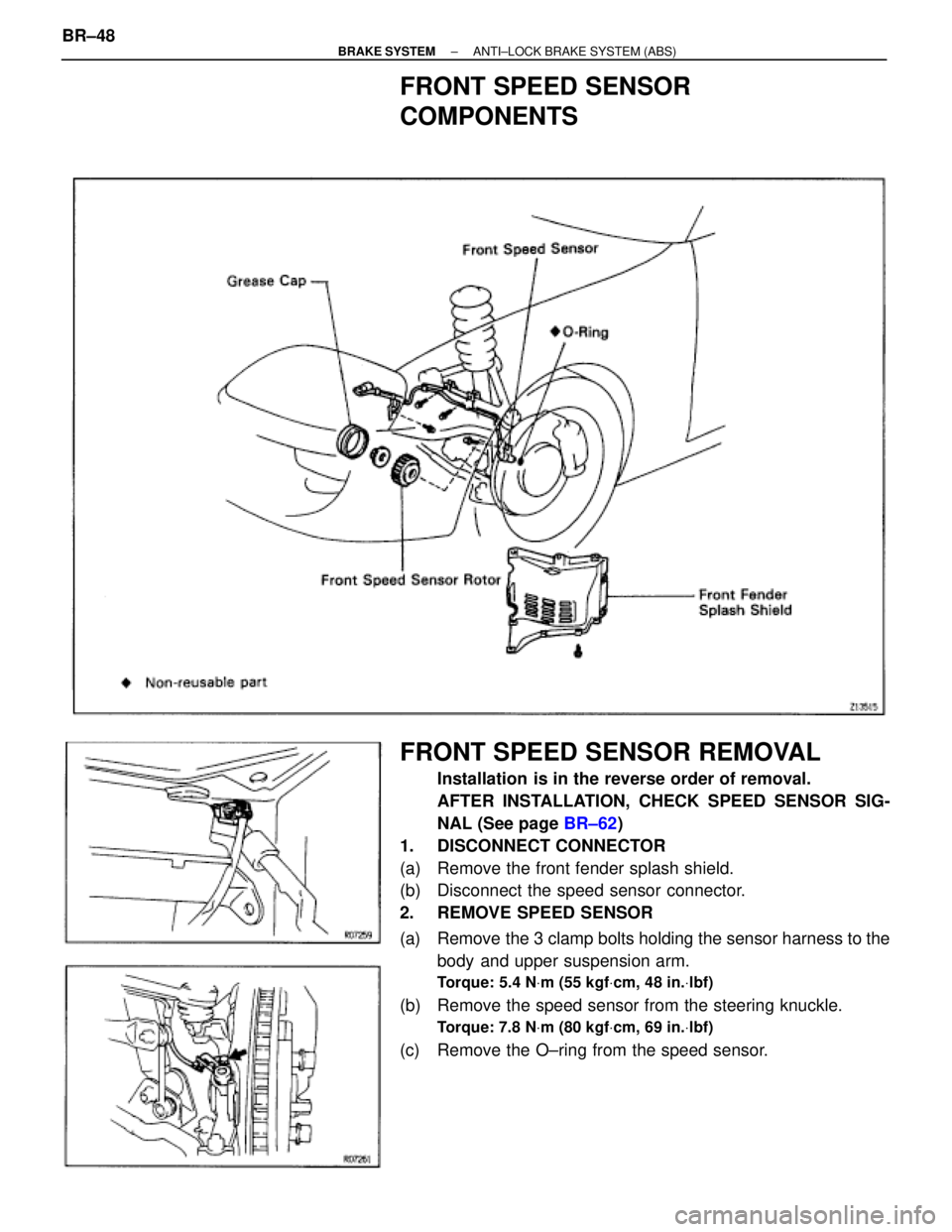
FRONT SPEED SENSOR
COMPONENTS
FRONT SPEED SENSOR REMOVAL
Installation is in the reverse order of removal.
AFTER INSTALLATION, CHECK SPEED SENSOR SIG-
NAL (See page BR±62)
1. DISCONNECT CONNECTOR
(a) Remove the front fender splash shield.
(b) Disconnect the speed sensor connector.
2. REMOVE SPEED SENSOR
(a) Remove the 3 clamp bolts holding the sensor harness to the
body and upper suspension arm.
Torque: 5.4 NVm (55 kgfVcm, 48 in.Vlbf)
(b) Remove the speed sensor from the steering knuckle.
Torque: 7.8 NVm (80 kgfVcm, 69 in.Vlbf)
(c) Remove the O±ring from the speed sensor. BR±48
± BRAKE SYSTEMANTI±LOCK BRAKE SYSTEM (ABS)
Page 918 of 2543
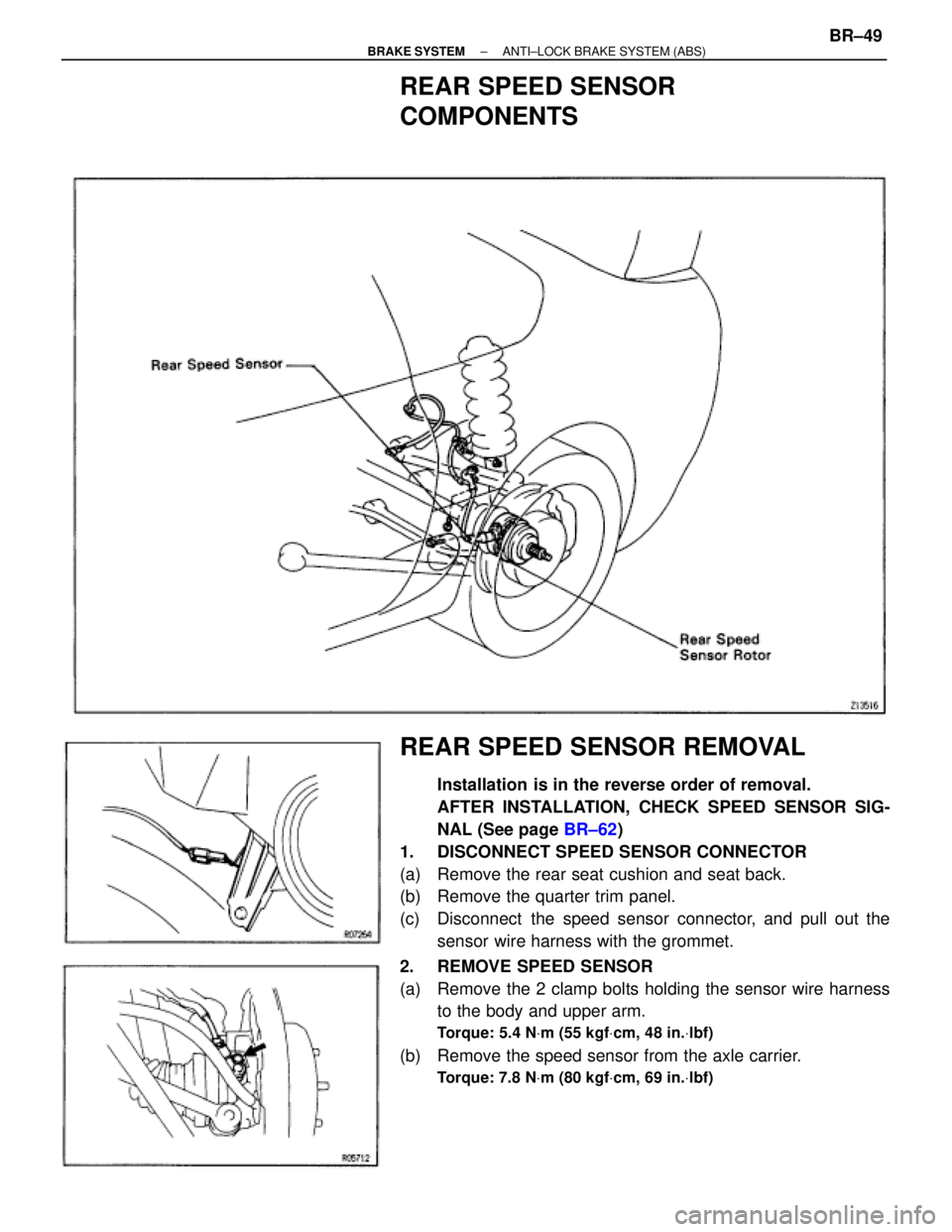
REAR SPEED SENSOR
COMPONENTS
REAR SPEED SENSOR REMOVAL
Installation is in the reverse order of removal.
AFTER INSTALLATION, CHECK SPEED SENSOR SIG-
NAL (See page BR±62)
1. DISCONNECT SPEED SENSOR CONNECTOR
(a) Remove the rear seat cushion and seat back.
(b) Remove the quarter trim panel.
(c) Disconnect the speed sensor connector, and pull out the
sensor wire harness with the grommet.
2. REMOVE SPEED SENSOR
(a) Remove the 2 clamp bolts holding the sensor wire harness
to the body and upper arm.
Torque: 5.4 NVm (55 kgfVcm, 48 in.Vlbf)
(b) Remove the speed sensor from the axle carrier.
Torque: 7.8 NVm (80 kgfVcm, 69 in.Vlbf)
± BRAKE SYSTEMANTI±LOCK BRAKE SYSTEM (ABS)BR±49
Page 919 of 2543
±MEMO± BR±50
± BRAKE SYSTEMANTI±LOCK BRAKE SYSTEM (ABS)
Page 920 of 2543
TROUBLESHOOTING
± BRAKE SYSTEMANTI±LOCK BRAKE SYSTEM (ABS)BR±51
Trending: Pump, differential, heater, manual transmission, rear view mirror, wheel bolt torque, ignition
