brake pads TOYOTA SUPRA 1995 Service Repair Manual
[x] Cancel search | Manufacturer: TOYOTA, Model Year: 1995, Model line: SUPRA, Model: TOYOTA SUPRA 1995Pages: 2543, PDF Size: 53.25 MB
Page 887 of 2543
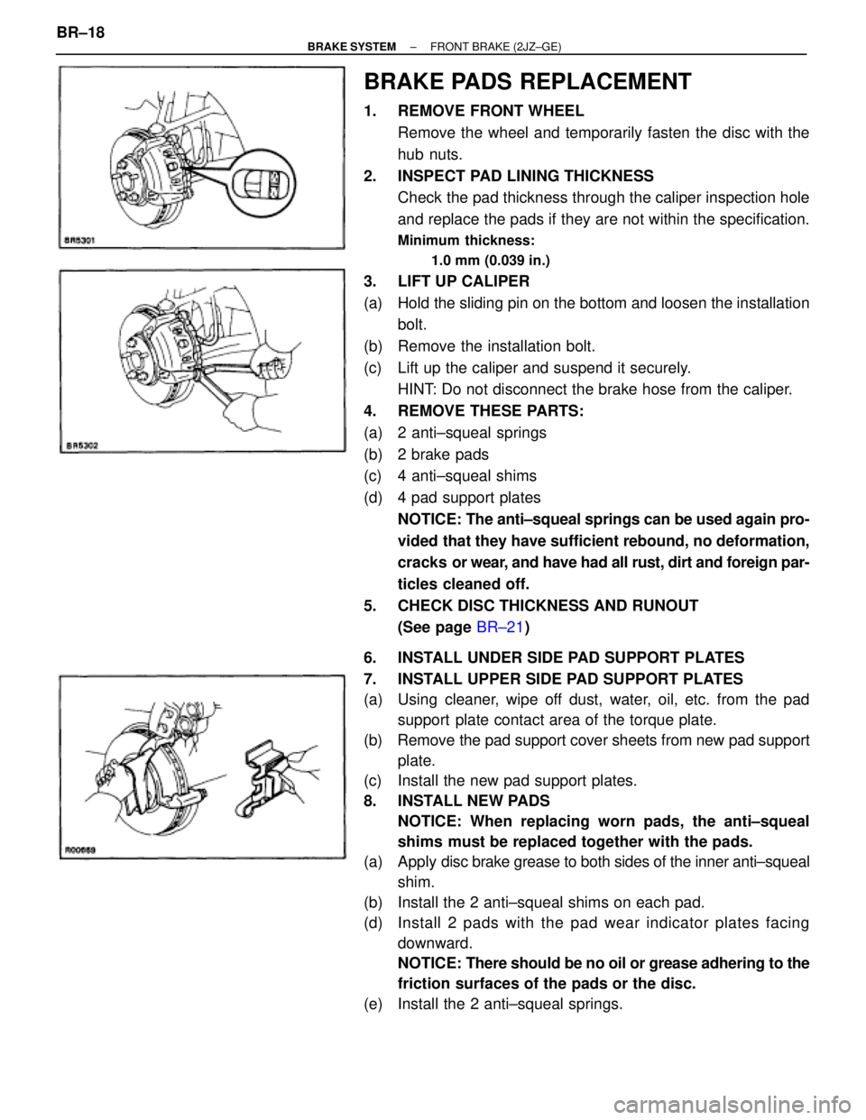
BRAKE PADS REPLACEMENT
1. REMOVE FRONT WHEEL
Remove the wheel and temporarily fasten the disc with the
hub nuts.
2. INSPECT PAD LINING THICKNESS
Check the pad thickness through the caliper inspection hole
and replace the pads if they are not within the specification.
Minimum thickness:
1.0 mm (0.039 in.)
3. LIFT UP CALIPER
(a) Hold the sliding pin on the bottom and loosen the installation
bolt.
(b) Remove the installation bolt.
(c) Lift up the caliper and suspend it securely.
HINT: Do not disconnect the brake hose from the caliper.
4. REMOVE THESE PARTS:
(a) 2 anti±squeal springs
(b) 2 brake pads
(c) 4 anti±squeal shims
(d) 4 pad support plates
NOTICE: The anti±squeal springs can be used again pro-
vided that they have sufficient rebound, no deformation,
cracks or wear, and have had all rust, dirt and foreign par-
ticles cleaned off.
5. CHECK DISC THICKNESS AND RUNOUT
(See page BR±21)
6. INSTALL UNDER SIDE PAD SUPPORT PLATES
7. INSTALL UPPER SIDE PAD SUPPORT PLATES
(a) Using cleaner, wipe off dust, water, oil, etc. from the pad
support plate contact area of the torque plate.
(b) Remove the pad support cover sheets from new pad support
plate.
(c) Install the new pad support plates.
8. INSTALL NEW PADS
NOTICE: When replacing worn pads, the anti±squeal
shims must be replaced together with the pads.
(a) Apply disc brake grease to both sides of the inner anti±squeal
shim.
(b) Install the 2 anti±squeal shims on each pad.
(d) Install 2 pads with the pad wear indicator plates facing
downward.
NOTICE: There should be no oil or grease adhering to the
friction surfaces of the pads or the disc.
(e) Install the 2 anti±squeal springs. BR±18
± BRAKE SYSTEMFRONT BRAKE (2JZ±GE)
Page 888 of 2543
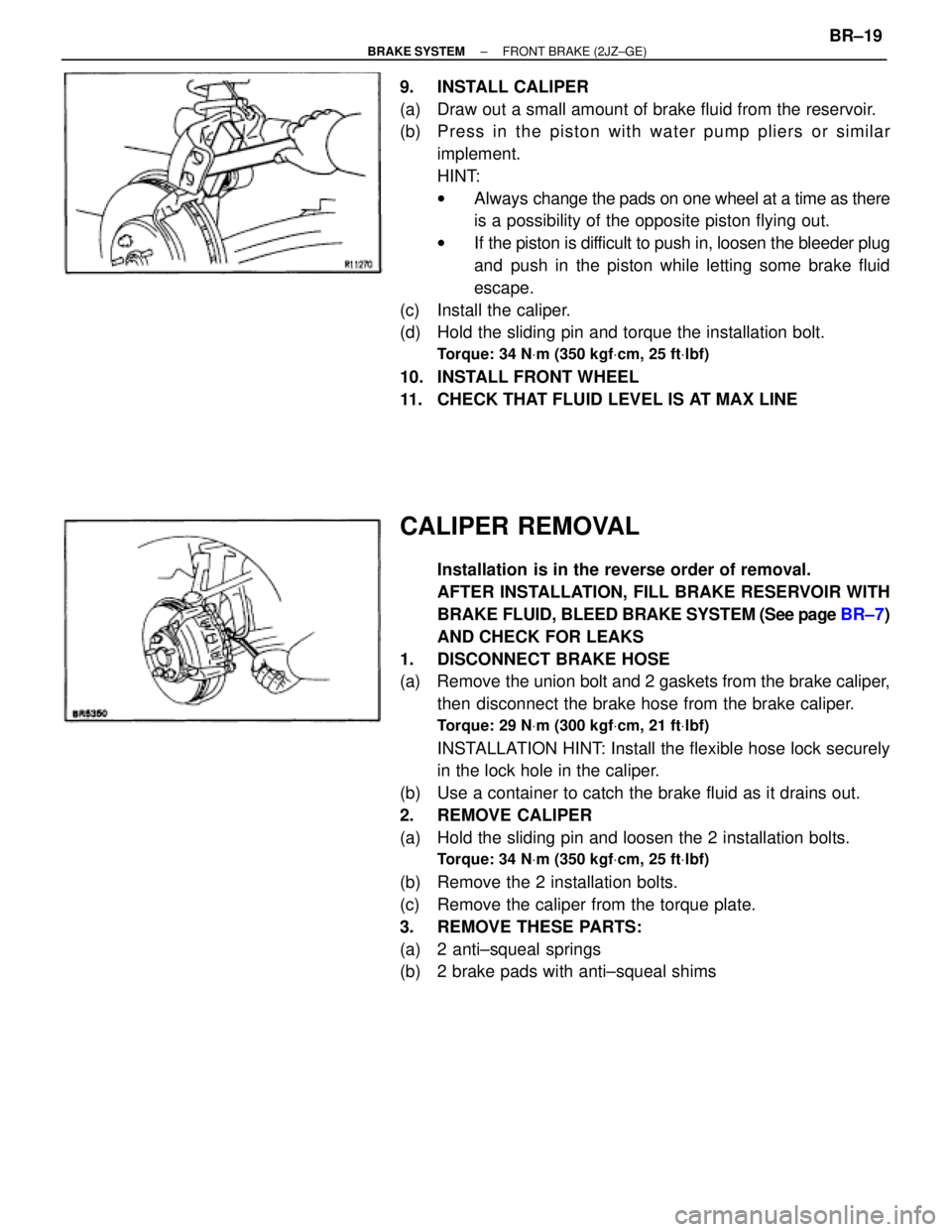
9. INSTALL CALIPER
(a) Draw out a small amount of brake fluid from the reservoir.
(b) P re ss in th e pisto n with wa te r pu mp plie rs or simila r
implement.
HINT:
wAlways change the pads on one wheel at a time as there
is a possibility of the opposite piston flying out.
wIf the piston is difficult to push in, loosen the bleeder plug
and push in the piston while letting some brake fluid
escape.
(c) Install the caliper.
(d) Hold the sliding pin and torque the installation bolt.
Torque: 34 NVm (350 kgfVcm, 25 ftVlbf)
10. INSTALL FRONT WHEEL
11. CHECK THAT FLUID LEVEL IS AT MAX LINE
CALIPER REMOVAL
Installation is in the reverse order of removal.
AFTER INSTALLATION, FILL BRAKE RESERVOIR WITH
BRAKE FLUID, BLEED BRAKE SYSTEM (See page BR±7)
AND CHECK FOR LEAKS
1. DISCONNECT BRAKE HOSE
(a) Remove the union bolt and 2 gaskets from the brake caliper,
then disconnect the brake hose from the brake caliper.
Torque: 29 NVm (300 kgfVcm, 21 ftVlbf)
INSTALLATION HINT: Install the flexible hose lock securely
in the lock hole in the caliper.
(b) Use a container to catch the brake fluid as it drains out.
2. REMOVE CALIPER
(a) Hold the sliding pin and loosen the 2 installation bolts.
Torque: 34 NVm (350 kgfVcm, 25 ftVlbf)
(b) Remove the 2 installation bolts.
(c) Remove the caliper from the torque plate.
3. REMOVE THESE PARTS:
(a) 2 anti±squeal springs
(b) 2 brake pads with anti±squeal shims
± BRAKE SYSTEMFRONT BRAKE (2JZ±GE)BR±19
Page 891 of 2543
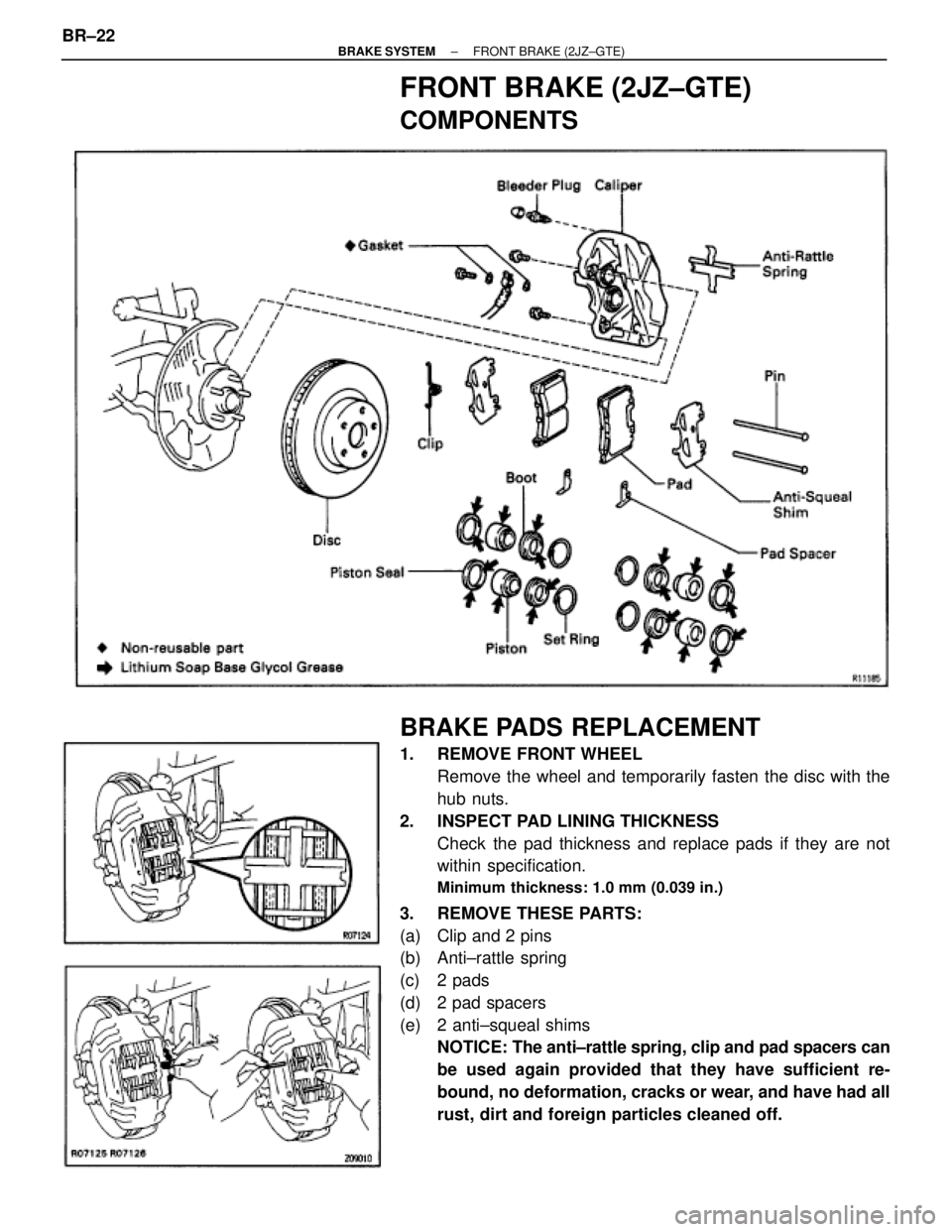
FRONT BRAKE (2JZ±GTE)
COMPONENTS
BRAKE PADS REPLACEMENT
1. REMOVE FRONT WHEEL
Remove the wheel and temporarily fasten the disc with the
hub nuts.
2. INSPECT PAD LINING THICKNESS
Check the pad thickness and replace pads if they are not
within specification.
Minimum thickness: 1.0 mm (0.039 in.)
3. REMOVE THESE PARTS:
(a) Clip and 2 pins
(b) Anti±rattle spring
(c) 2 pads
(d) 2 pad spacers
(e) 2 anti±squeal shims
NOTICE: The anti±rattle spring, clip and pad spacers can
be used again provided that they have sufficient re-
bound, no deformation, cracks or wear, and have had all
rust, dirt and foreign particles cleaned off. BR±22
± BRAKE SYSTEMFRONT BRAKE (2JZ±GTE)
Page 892 of 2543
4. CHECK DISC THICKNESS AND RUNOUT
(See page BR±25)
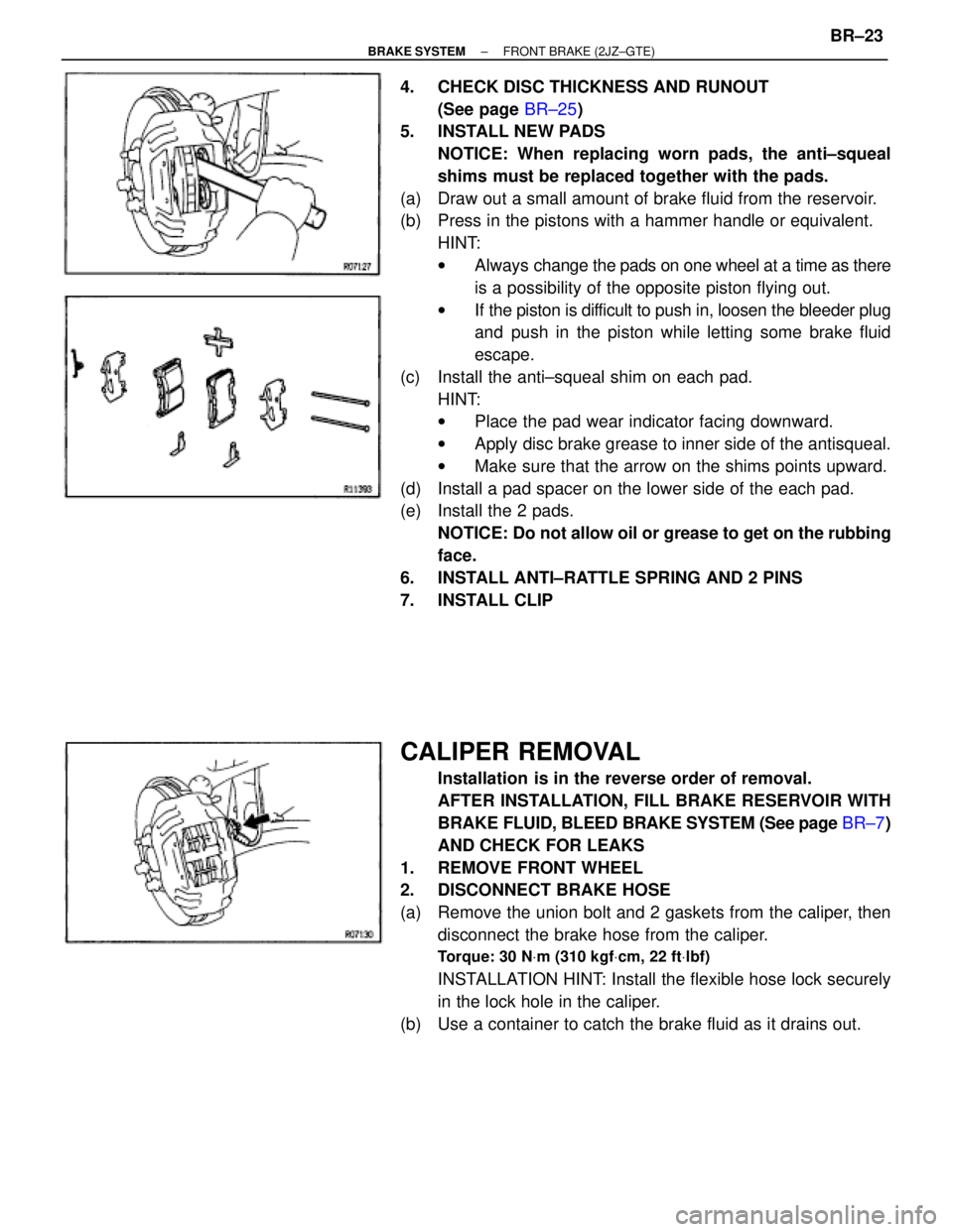
5. INSTALL NEW PADS
NOTICE: When replacing worn pads, the anti±squeal
shims must be replaced together with the pads.
(a) Draw out a small amount of brake fluid from the reservoir.
(b) Press in the pistons with a hammer handle or equivalent.
HINT:
wAlways change the pads on one wheel at a time as there
is a possibility of the opposite piston flying out.
wIf the piston is difficult to push in, loosen the bleeder plug
and push in the piston while letting some brake fluid
escape.
(c) Install the anti±squeal shim on each pad.
HINT:
wPlace the pad wear indicator facing downward.
wApply disc brake grease to inner side of the antisqueal.
wMake sure that the arrow on the shims points upward.
(d) Install a pad spacer on the lower side of the each pad.
(e) Install the 2 pads.
NOTICE: Do not allow oil or grease to get on the rubbing
face.
6. INSTALL ANTI±RATTLE SPRING AND 2 PINS
7. INSTALL CLIP
CALIPER REMOVAL
Installation is in the reverse order of removal.
AFTER INSTALLATION, FILL BRAKE RESERVOIR WITH
BRAKE FLUID, BLEED BRAKE SYSTEM (See page BR±7)
AND CHECK FOR LEAKS
1. REMOVE FRONT WHEEL
2. DISCONNECT BRAKE HOSE
(a) Remove the union bolt and 2 gaskets from the caliper, then
disconnect the brake hose from the caliper.
Torque: 30 NVm (310 kgfVcm, 22 ftVlbf)
INSTALLATION HINT: Install the flexible hose lock securely
in the lock hole in the caliper.
(b) Use a container to catch the brake fluid as it drains out.
± BRAKE SYSTEMFRONT BRAKE (2JZ±GTE)BR±23
Page 893 of 2543
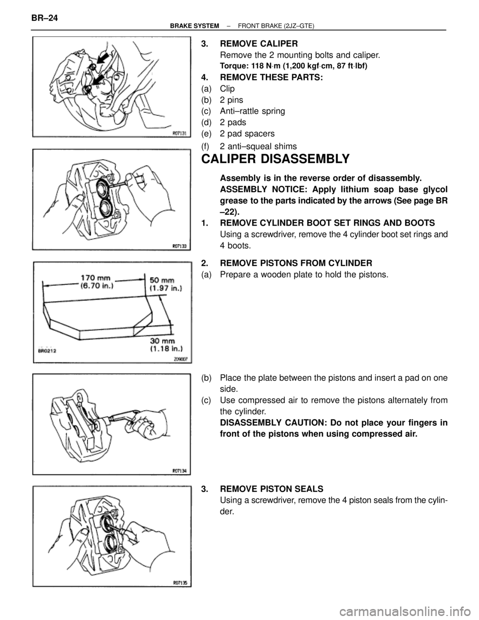
3. REMOVE CALIPER
Remove the 2 mounting bolts and caliper.
Torque: 118 NVm (1,200 kgfVcm, 87 ftVlbf)
4. REMOVE THESE PARTS:
(a) Clip
(b) 2 pins
(c) Anti±rattle spring
(d) 2 pads
(e) 2 pad spacers
(f) 2 anti±squeal shims
CALIPER DISASSEMBLY
Assembly is in the reverse order of disassembly.
ASSEMBLY NOTICE: Apply lithium soap base glycol
grease to the parts indicated by the arrows (See page BR
±22).
1. REMOVE CYLINDER BOOT SET RINGS AND BOOTS
Using a screwdriver, remove the 4 cylinder boot set rings and
4 boots.
2. REMOVE PISTONS FROM CYLINDER
(a) Prepare a wooden plate to hold the pistons.
(b) Place the plate between the pistons and insert a pad on one
side.
(c) Use compressed air to remove the pistons alternately from
the cylinder.
DISASSEMBLY CAUTION: Do not place your fingers in
front of the pistons when using compressed air.
3. REMOVE PISTON SEALS
Using a screwdriver, remove the 4 piston seals from the cylin-
der. BR±24
± BRAKE SYSTEMFRONT BRAKE (2JZ±GTE)
Page 894 of 2543
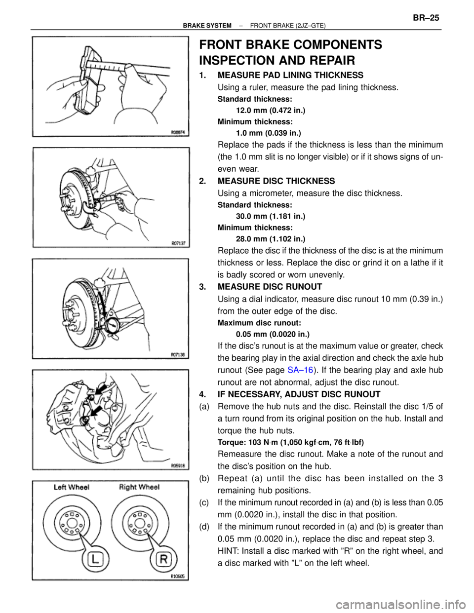
FRONT BRAKE COMPONENTS
INSPECTION AND REPAIR
1. MEASURE PAD LINING THICKNESS
Using a ruler, measure the pad lining thickness.
Standard thickness:
12.0 mm (0.472 in.)
Minimum thickness:
1.0 mm (0.039 in.)
Replace the pads if the thickness is less than the minimum
(the 1.0 mm slit is no longer visible) or if it shows signs of un-
even wear.
2. MEASURE DISC THICKNESS
Using a micrometer, measure the disc thickness.
Standard thickness:
30.0 mm (1.181 in.)
Minimum thickness:
28.0 mm (1.102 in.)
Replace the disc if the thickness of the disc is at the minimum
thickness or less. Replace the disc or grind it on a lathe if it
is badly scored or worn unevenly.
3. MEASURE DISC RUNOUT
Using a dial indicator, measure disc runout 10 mm (0.39 in.)
from the outer edge of the disc.
Maximum disc runout:
0.05 mm (0.0020 in.)
If the disc's runout is at the maximum value or greater, check
the bearing play in the axial direction and check the axle hub
runout (See page SA±16). If the bearing play and axle hub
runout are not abnormal, adjust the disc runout.
4. IF NECESSARY, ADJUST DISC RUNOUT
(a) Remove the hub nuts and the disc. Reinstall the disc 1/5 of
a turn round from its original position on the hub. Install and
torque the hub nuts.
Torque: 103 NVm (1,050 kgfVcm, 76 ftVlbf)
Remeasure the disc runout. Make a note of the runout and
the disc's position on the hub.
(b) Repeat (a) until the disc has been installed on the 3
remaining hub positions.
(c) If the minimum runout recorded in (a) and (b) is less than 0.05
mm (0.0020 in.), install the disc in that position.
(d) If the minimum runout recorded in (a) and (b) is greater than
0.05 mm (0.0020 in.), replace the disc and repeat step 3.
HINT: Install a disc marked with ºRº on the right wheel, and
a disc marked with ºLº on the left wheel.
± BRAKE SYSTEMFRONT BRAKE (2JZ±GTE)BR±25
Page 896 of 2543
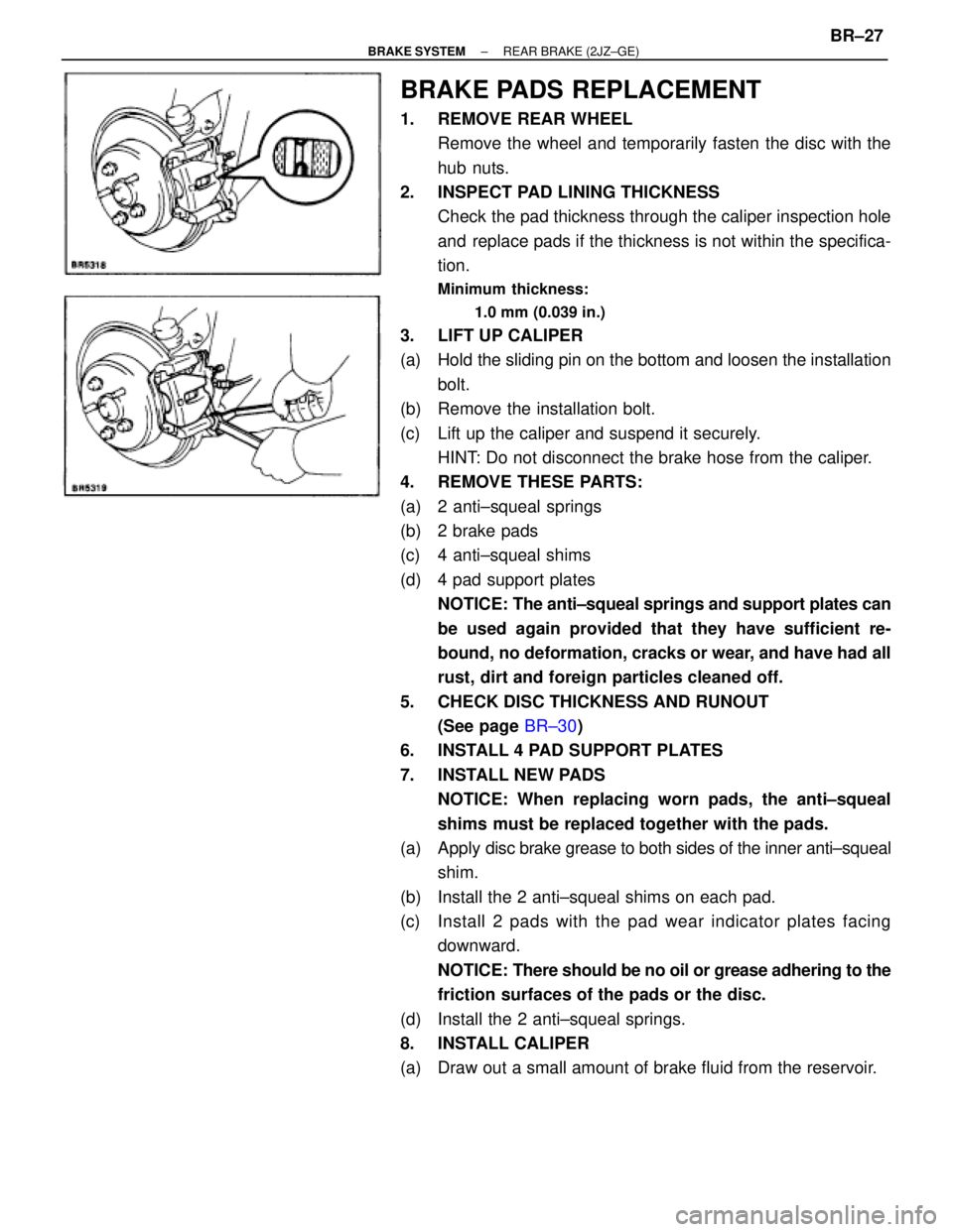
BRAKE PADS REPLACEMENT
1. REMOVE REAR WHEEL
Remove the wheel and temporarily fasten the disc with the
hub nuts.
2. INSPECT PAD LINING THICKNESS
Check the pad thickness through the caliper inspection hole
and replace pads if the thickness is not within the specifica-
tion.
Minimum thickness:
1.0 mm (0.039 in.)
3. LIFT UP CALIPER
(a) Hold the sliding pin on the bottom and loosen the installation
bolt.
(b) Remove the installation bolt.
(c) Lift up the caliper and suspend it securely.
HINT: Do not disconnect the brake hose from the caliper.
4. REMOVE THESE PARTS:
(a) 2 anti±squeal springs
(b) 2 brake pads
(c) 4 anti±squeal shims
(d) 4 pad support plates
NOTICE: The anti±squeal springs and support plates can
be used again provided that they have sufficient re-
bound, no deformation, cracks or wear, and have had all
rust, dirt and foreign particles cleaned off.
5. CHECK DISC THICKNESS AND RUNOUT
(See page BR±30)
6. INSTALL 4 PAD SUPPORT PLATES
7. INSTALL NEW PADS
NOTICE: When replacing worn pads, the anti±squeal
shims must be replaced together with the pads.
(a) Apply disc brake grease to both sides of the inner anti±squeal
shim.
(b) Install the 2 anti±squeal shims on each pad.
(c) Install 2 pads with the pad wear indicator plates facing
downward.
NOTICE: There should be no oil or grease adhering to the
friction surfaces of the pads or the disc.
(d) Install the 2 anti±squeal springs.
8. INSTALL CALIPER
(a) Draw out a small amount of brake fluid from the reservoir.
± BRAKE SYSTEMREAR BRAKE (2JZ±GE)BR±27
Page 897 of 2543
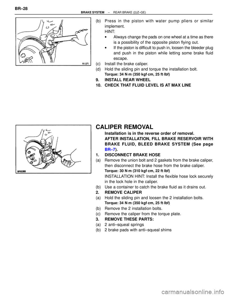
(b) Press in the piston with water pump pliers or similar
implement.
HINT:
wAlways change the pads on one wheel at a time as there
is a possibility of the opposite piston flying out.
wIf the piston is difficult to push in, loosen the bleeder plug
and push in the piston while letting some brake fluid
escape.
(c) Install the brake caliper.
(d) Hold the sliding pin and torque the installation bolt.
Torque: 34 NVm (350 kgfVcm, 25 ftVlbf)
9. INSTALL REAR WHEEL
10. CHECK THAT FLUID LEVEL IS AT MAX LINE
CALIPER REMOVAL
Installation is in the reverse order of removal.
AFTER INSTALLATION, FILL BRAKE RESERVOIR WITH
BRAKE FLUID, BLEED BRAKE SYSTEM (See page
BR±7).
1. DISCONNECT BRAKE HOSE
(a) Remove the union bolt and 2 gaskets from the brake caliper,
then disconnect the brake hose from the brake caliper.
Torque: 30 NVm (310 kgfVcm, 22 ftVlbf)
INSTALLATION HINT: Install the flexible hose lock securely
in the lock hole in the caliper.
(b) Use a container to catch the brake fluid as it drains out.
2. REMOVE CALIPER
(a) Hold the sliding pin and loosen the 2 installation bolts.
Torque: 34 NVm (350 kgfVcm, 25 ftVlbf)
(b) Remove the 2 installation bolts.
(c) Remove the caliper from the torque plate.
3. REMOVE THESE PARTS:
(a) 2 anti±squeal springs
(b) 2 brake pads with anti±squeal shims BR±28
± BRAKE SYSTEMREAR BRAKE (2JZ±GE)
Page 900 of 2543
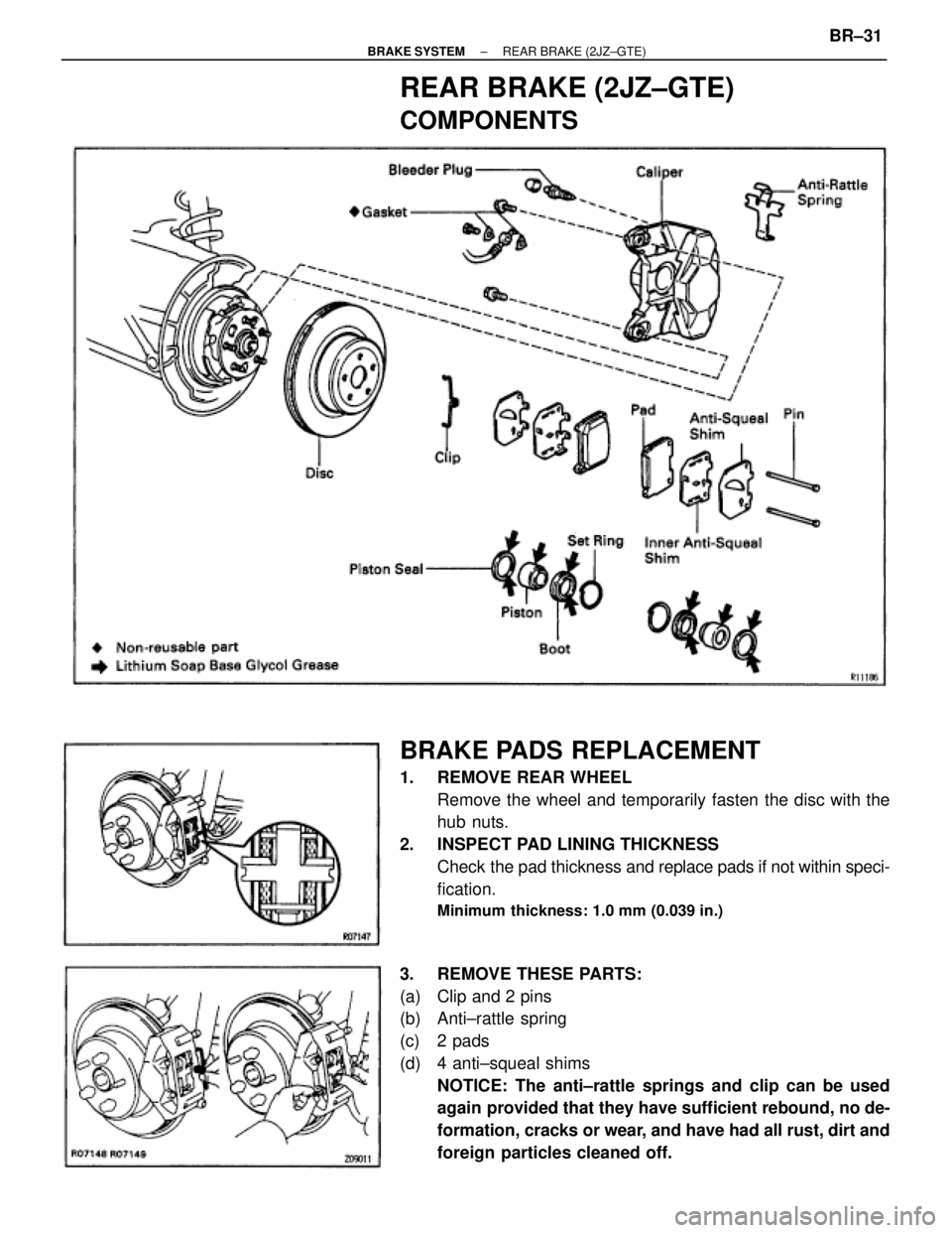
REAR BRAKE (2JZ±GTE)
COMPONENTS
BRAKE PADS REPLACEMENT
1. REMOVE REAR WHEEL
Remove the wheel and temporarily fasten the disc with the
hub nuts.
2. INSPECT PAD LINING THICKNESS
Check the pad thickness and replace pads if not within speci-
fication.
Minimum thickness: 1.0 mm (0.039 in.)
3. REMOVE THESE PARTS:
(a) Clip and 2 pins
(b) Anti±rattle spring
(c) 2 pads
(d) 4 anti±squeal shims
NOTICE: The anti±rattle springs and clip can be used
again provided that they have sufficient rebound, no de-
formation, cracks or wear, and have had all rust, dirt and
foreign particles cleaned off.
± BRAKE SYSTEMREAR BRAKE (2JZ±GTE)BR±31
Page 901 of 2543
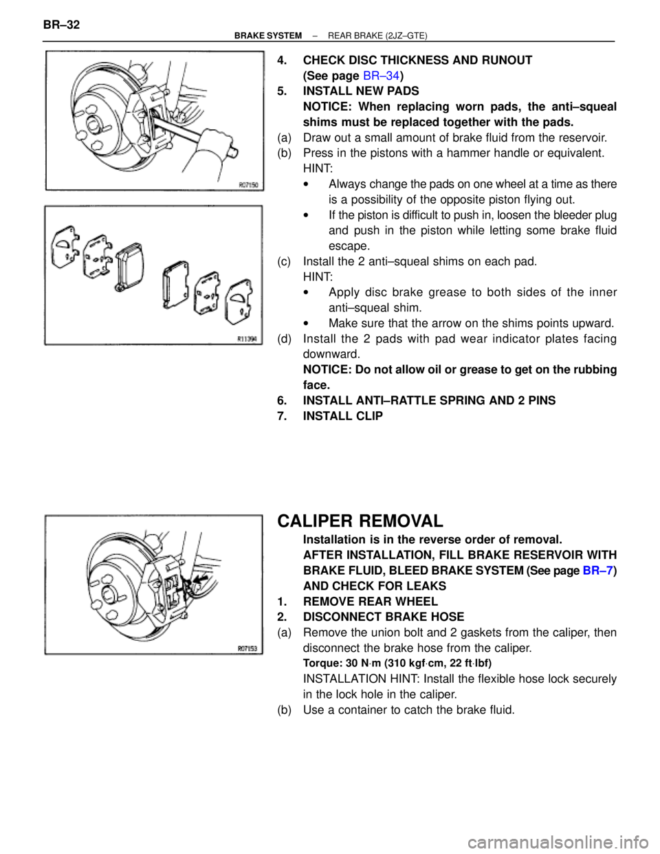
4. CHECK DISC THICKNESS AND RUNOUT
(See page BR±34)
5. INSTALL NEW PADS
NOTICE: When replacing worn pads, the anti±squeal
shims must be replaced together with the pads.
(a) Draw out a small amount of brake fluid from the reservoir.
(b) Press in the pistons with a hammer handle or equivalent.
HINT:
wAlways change the pads on one wheel at a time as there
is a possibility of the opposite piston flying out.
wIf the piston is difficult to push in, loosen the bleeder plug
and push in the piston while letting some brake fluid
escape.
(c) Install the 2 anti±squeal shims on each pad.
HINT:
wApply disc brake grease to both sides of the inner
anti±squeal shim.
wMake sure that the arrow on the shims points upward.
(d) Install the 2 pads with pad wear indicator plates facing
downward.
NOTICE: Do not allow oil or grease to get on the rubbing
face.
6. INSTALL ANTI±RATTLE SPRING AND 2 PINS
7. INSTALL CLIP
CALIPER REMOVAL
Installation is in the reverse order of removal.
AFTER INSTALLATION, FILL BRAKE RESERVOIR WITH
BRAKE FLUID, BLEED BRAKE SYSTEM (See page BR±7)
AND CHECK FOR LEAKS
1. REMOVE REAR WHEEL
2. DISCONNECT BRAKE HOSE
(a) Remove the union bolt and 2 gaskets from the caliper, then
disconnect the brake hose from the caliper.
Torque: 30 NVm (310 kgfVcm, 22 ftVlbf)
INSTALLATION HINT: Install the flexible hose lock securely
in the lock hole in the caliper.
(b) Use a container to catch the brake fluid. BR±32
± BRAKE SYSTEMREAR BRAKE (2JZ±GTE)