roof rack TOYOTA SUPRA 1995 Service Repair Manual
[x] Cancel search | Manufacturer: TOYOTA, Model Year: 1995, Model line: SUPRA, Model: TOYOTA SUPRA 1995Pages: 2543, PDF Size: 53.25 MB
Page 410 of 2543
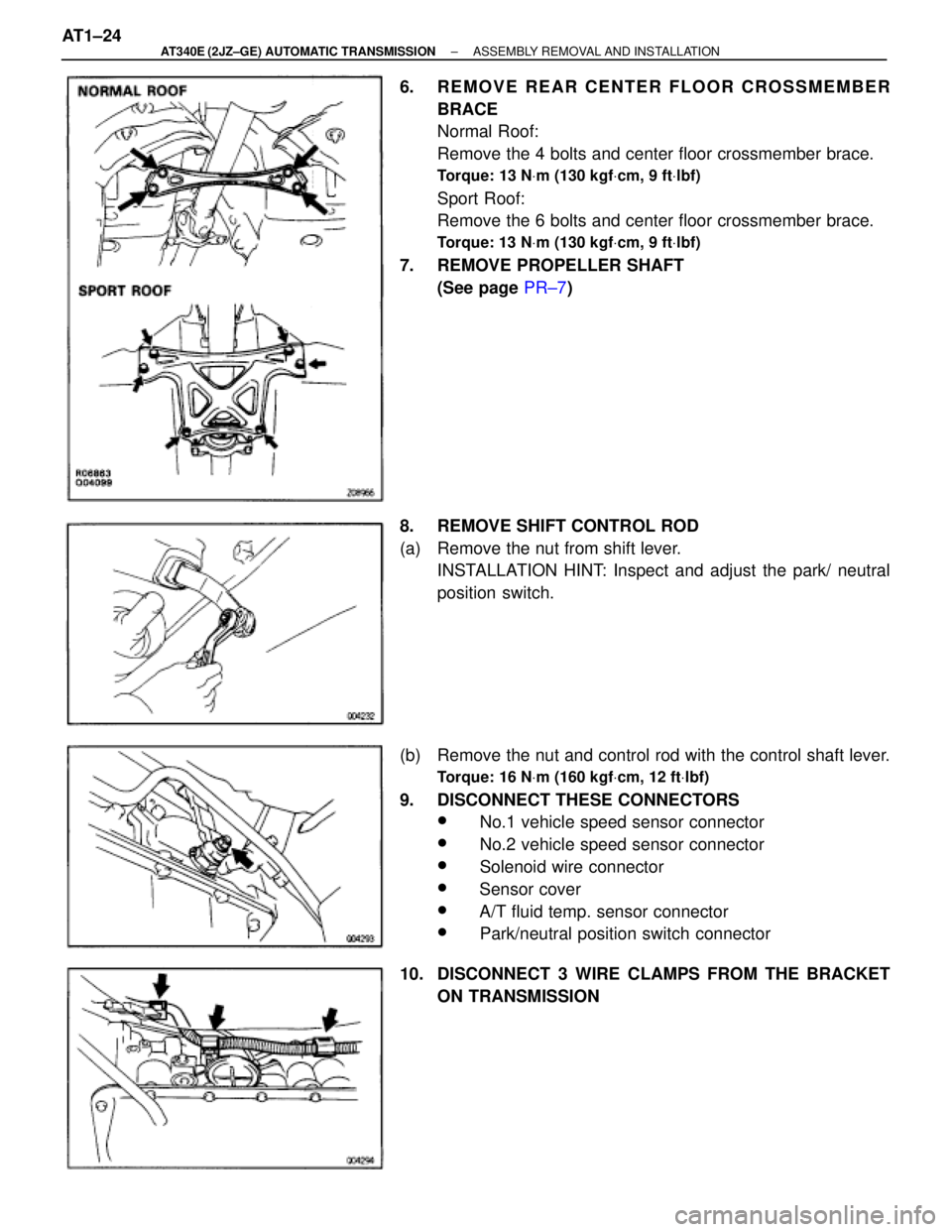
6. REMOVE REAR CENTER FLOOR CROSSMEMBER
BRACE
Normal Roof:
Remove the 4 bolts and center floor crossmember brace.
Torque: 13 NVm (130 kgfVcm, 9 ftVlbf)
Sport Roof:
Remove the 6 bolts and center floor crossmember brace.
Torque: 13 NVm (130 kgfVcm, 9 ftVlbf)
7. REMOVE PROPELLER SHAFT
(See page PR±7)
8. REMOVE SHIFT CONTROL ROD
(a) Remove the nut from shift lever.
INSTALLATION HINT: Inspect and adjust the park/ neutral
position switch.
(b) Remove the nut and control rod with the control shaft lever.
Torque: 16 NVm (160 kgfVcm, 12 ftVlbf)
9. DISCONNECT THESE CONNECTORS
w No.1 vehicle speed sensor connector
w No.2 vehicle speed sensor connector
w Solenoid wire connector
w Sensor cover
w A/T fluid temp. sensor connector
w Park/neutral position switch connector
10. DISCONNECT 3 WIRE CLAMPS FROM THE BRACKET
ON TRANSMISSION AT1±24
± AT340E (2JZ±GE) AUTOMATIC TRANSMISSIONASSEMBLY REMOVAL AND INSTALLATION
Page 848 of 2543
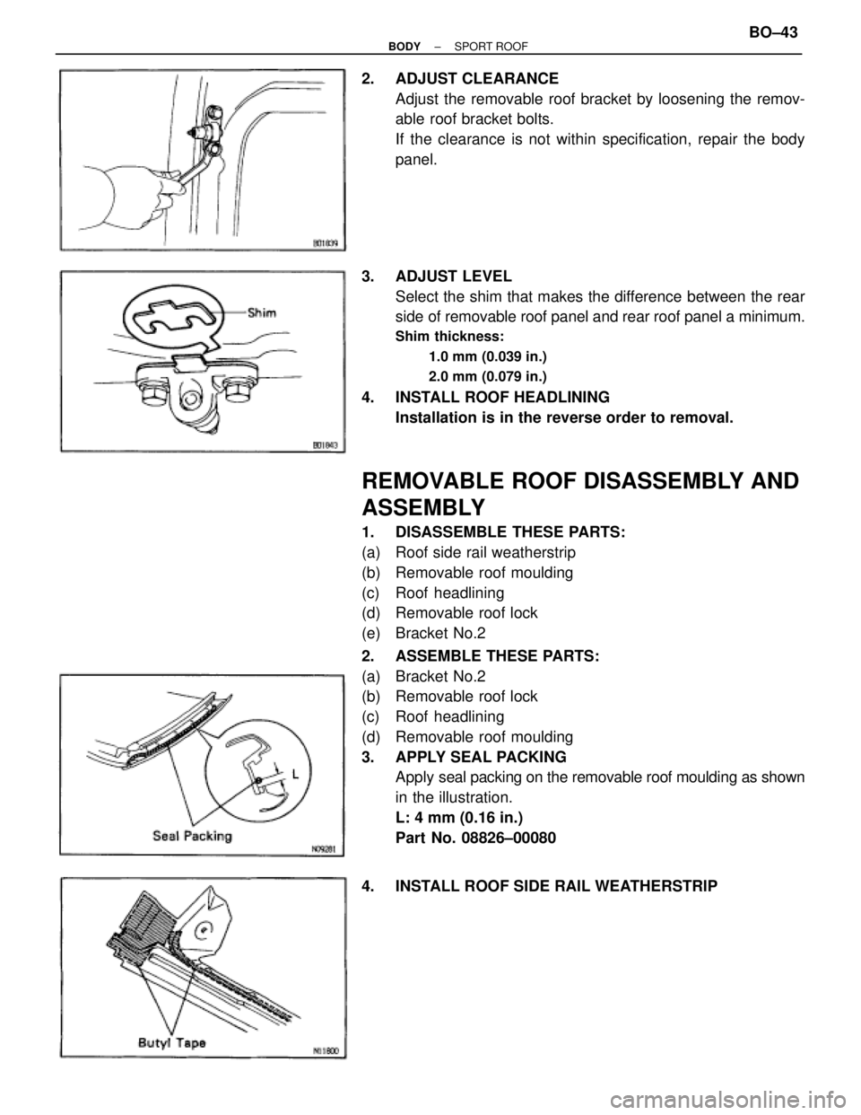
2. ADJUST CLEARANCE
Adjust the removable roof bracket by loosening the remov-
able roof bracket bolts.
If the clearance is not within specification, repair the body
panel.
3. ADJUST LEVEL
Select the shim that makes the difference between the rear
side of removable roof panel and rear roof panel a minimum.
Shim thickness:
1.0 mm (0.039 in.)
2.0 mm (0.079 in.)
4. INSTALL ROOF HEADLINING
Installation is in the reverse order to removal.
REMOVABLE ROOF DISASSEMBLY AND
ASSEMBLY
1. DISASSEMBLE THESE PARTS:
(a) Roof side rail weatherstrip
(b) Removable roof moulding
(c) Roof headlining
(d) Removable roof lock
(e) Bracket No.2
2. ASSEMBLE THESE PARTS:
(a) Bracket No.2
(b) Removable roof lock
(c) Roof headlining
(d) Removable roof moulding
3. APPLY SEAL PACKING
Apply seal packing on the removable roof moulding as shown
in the illustration.
L: 4 mm (0.16 in.)
Part No. 08826±00080
4. INSTALL ROOF SIDE RAIL WEATHERSTRIP
± BODYSPORT ROOFBO±43
Page 1275 of 2543
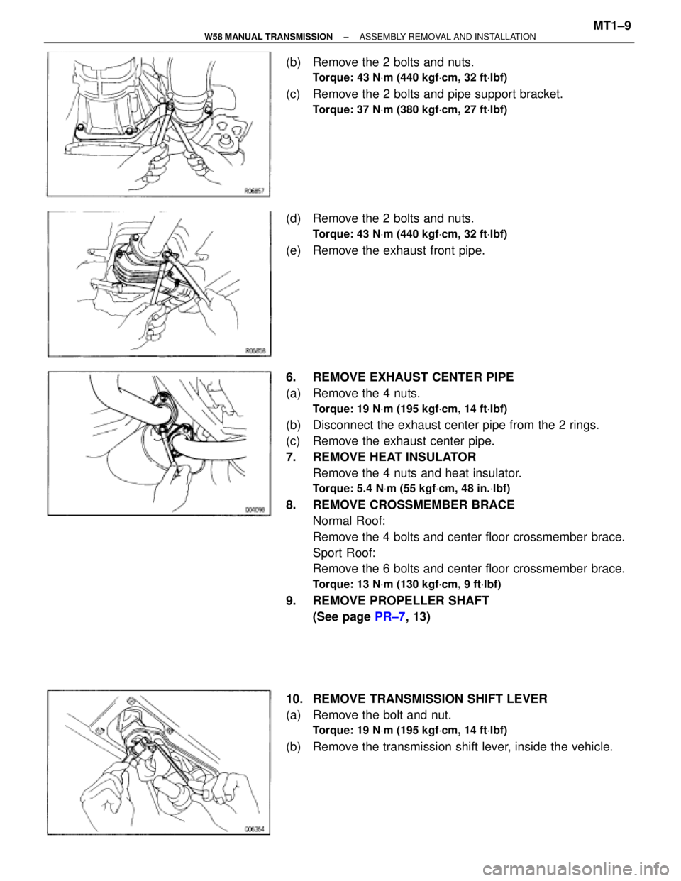
(b) Remove the 2 bolts and nuts.
Torque: 43 NVm (440 kgfVcm, 32 ftVlbf)
(c) Remove the 2 bolts and pipe support bracket.
Torque: 37 NVm (380 kgfVcm, 27 ftVlbf)
(d) Remove the 2 bolts and nuts.
Torque: 43 NVm (440 kgfVcm, 32 ftVlbf)
(e) Remove the exhaust front pipe.
6. REMOVE EXHAUST CENTER PIPE
(a) Remove the 4 nuts.
Torque: 19 NVm (195 kgfVcm, 14 ftVlbf)
(b) Disconnect the exhaust center pipe from the 2 rings.
(c) Remove the exhaust center pipe.
7. REMOVE HEAT INSULATOR
Remove the 4 nuts and heat insulator.
Torque: 5.4 NVm (55 kgfVcm, 48 in.Vlbf)
8. REMOVE CROSSMEMBER BRACE
Normal Roof:
Remove the 4 bolts and center floor crossmember brace.
Sport Roof:
Remove the 6 bolts and center floor crossmember brace.
Torque: 13 NVm (130 kgfVcm, 9 ftVlbf)
9. REMOVE PROPELLER SHAFT
(See page PR±7, 13)
10. REMOVE TRANSMISSION SHIFT LEVER
(a) Remove the bolt and nut.
Torque: 19 NVm (195 kgfVcm, 14 ftVlbf)
(b) Remove the transmission shift lever, inside the vehicle.
± W58 MANUAL TRANSMISSIONASSEMBLY REMOVAL AND INSTALLATIONMT1±9
Page 1405 of 2543
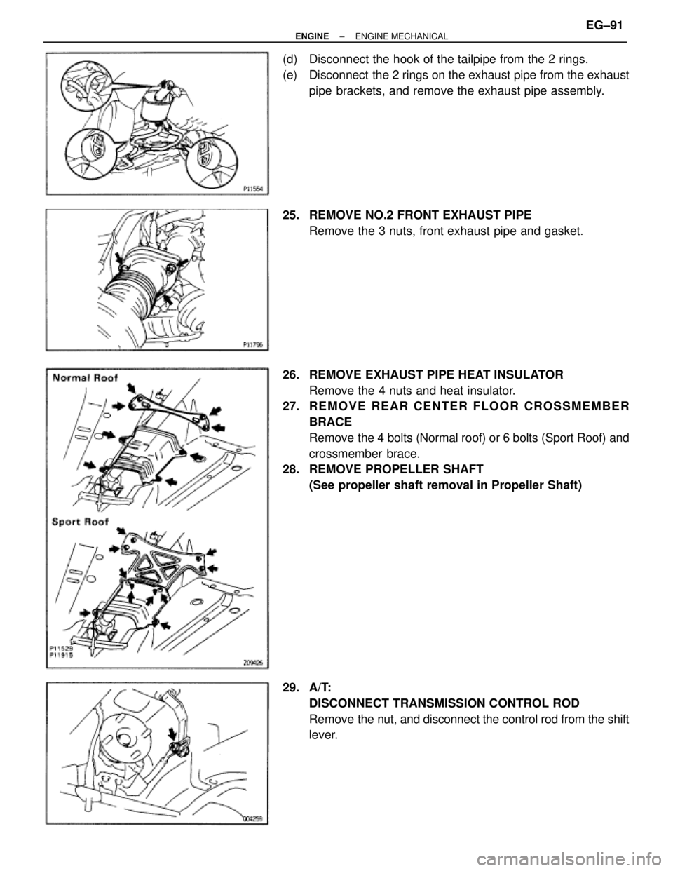
(d) Disconnect the hook of the tailpipe from the 2 rings.
(e) Disconnect the 2 rings on the exhaust pipe from the exhaust
pipe brackets, and remove the exhaust pipe assembly.
25. REMOVE NO.2 FRONT EXHAUST PIPE
Remove the 3 nuts, front exhaust pipe and gasket.
26. REMOVE EXHAUST PIPE HEAT INSULATOR
Remove the 4 nuts and heat insulator.
27. R E M O V E R E A R C E N T E R F L O O R C R O S S M E M B E R
BRACE
Remove the 4 bolts (Normal roof) or 6 bolts (Sport Roof) and
crossmember brace.
28. REMOVE PROPELLER SHAFT
(See propeller shaft removal in Propeller Shaft)
29. A/T:
DISCONNECT TRANSMISSION CONTROL ROD
Remove the nut, and disconnect the control rod from the shift
lever.
± ENGINEENGINE MECHANICALEG±91
Page 1461 of 2543
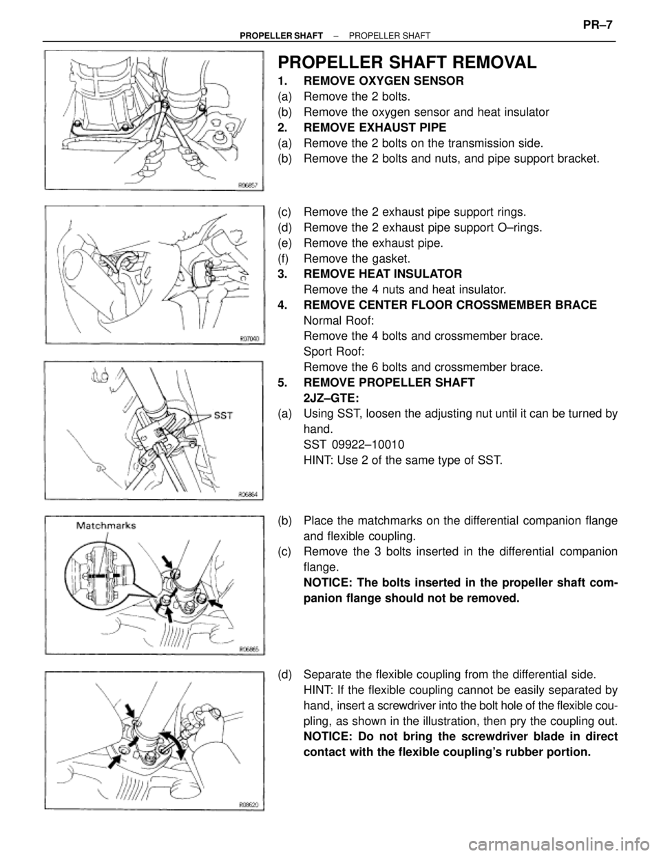
PROPELLER SHAFT REMOVAL
1. REMOVE OXYGEN SENSOR
(a) Remove the 2 bolts.
(b) Remove the oxygen sensor and heat insulator
2. REMOVE EXHAUST PIPE
(a) Remove the 2 bolts on the transmission side.
(b) Remove the 2 bolts and nuts, and pipe support bracket.
(c) Remove the 2 exhaust pipe support rings.
(d) Remove the 2 exhaust pipe support O±rings.
(e) Remove the exhaust pipe.
(f) Remove the gasket.
3. REMOVE HEAT INSULATOR
Remove the 4 nuts and heat insulator.
4. REMOVE CENTER FLOOR CROSSMEMBER BRACE
Normal Roof:
Remove the 4 bolts and crossmember brace.
Sport Roof:
Remove the 6 bolts and crossmember brace.
5. REMOVE PROPELLER SHAFT
2JZ±GTE:
(a) Using SST, loosen the adjusting nut until it can be turned by
hand.
SST 09922±10010
HINT: Use 2 of the same type of SST.
(b) Place the matchmarks on the differential companion flange
and flexible coupling.
(c) Remove the 3 bolts inserted in the differential companion
flange.
NOTICE: The bolts inserted in the propeller shaft com-
panion flange should not be removed.
(d) Separate the flexible coupling from the differential side.
HINT: If the flexible coupling cannot be easily separated by
hand, insert a screwdriver into the bolt hole of the flexible cou-
pling, as shown in the illustration, then pry the coupling out.
NOTICE: Do not bring the screwdriver blade in direct
contact with the flexible coupling's rubber portion.
± PROPELLER SHAFTPROPELLER SHAFTPR±7
Page 1470 of 2543
2. INSPECT PROPELLER SHAFT JOINT ANGLE
(See page PR±17)
NOTICE: The joint angle should be checked when the
propeller shaft is removed and installed.
3. INSTALL CROSSMEMBER BRACE
Normal Roof:
Install the center floor crossmember brace and torque the 4
bolts.
Torque: 13 NVm (130 kgfVcm, 8 ftVlbf)
Sport Roof:
Install the center floor crossmember brace and torque the 6
bolts.
Torque: 13 NVm (130 kgfVcm, 8 ftVlbf)
4. INSTALL HEAT INSULATOR
Install the heat insulator and torque the 4 nuts.
Torque: 5.4 NVm (55 kgfVcm, 48 in.Vlbf)
5. INSTALL EXHAUST PIPE
(a) Install a new gasket.
(b) Insert the exhaust pipe.
(c) Install the exhaust pipe to the 2 exhaust pipe support rings.
(d) Install the exhaust pipe to the 2 exhaust pipe support
O±rings.
(e) Temporary install the pipe support bracket to the
transmission with 2 bolts.
(f) Install the exhaust pipe with the 2 bolts and new 2 nuts.
Torque: 58 NVm (590 kgfVcm, 43 ftVlbf)
(g) Torque the 2 bolts.
Torque: 37 NVm (380 kgfVcm, 27 ftVlbf)
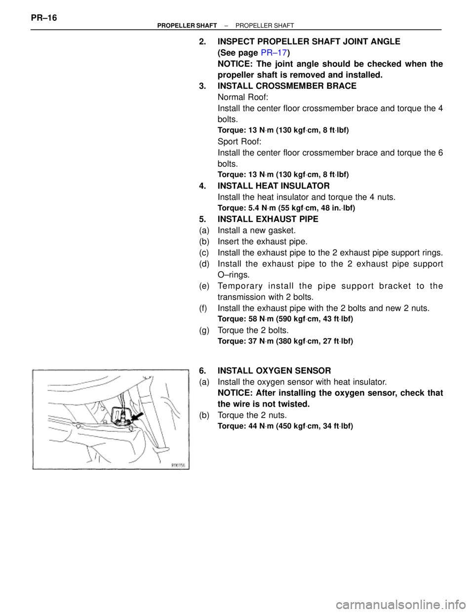
6. INSTALL OXYGEN SENSOR
(a) Install the oxygen sensor with heat insulator.
NOTICE: After installing the oxygen sensor, check that
the wire is not twisted.
(b) Torque the 2 nuts.
Torque: 44 NVm (450 kgfVcm, 34 ftVlbf)
PR±16± PROPELLER SHAFTPROPELLER SHAFT