width TOYOTA TACOMA 2019 Owners Manual (in English)
[x] Cancel search | Manufacturer: TOYOTA, Model Year: 2019, Model line: TACOMA, Model: TOYOTA TACOMA 2019Pages: 700, PDF Size: 12.83 MB
Page 254 of 700
2544-5. Using the driving support systems
■Operation conditio ns of each function
● Lane departure alert function
This function operates when all of the following conditions are met.
• LDA is turned on.
• Vehicle speed is approximately 32 mph (50 km/h) or more.
• System recognizes white (yellow) lines.
• Width of traffic lane is approximately 9.8 ft. (3 m) or more.
• Turn signal lever is not operated.
• Vehicle is driven on a straight road or around a gentle curve with a radius
of more than approximately 492 ft. (150 m).
• No system malfunctions are detected. ( P. 568)
● Vehicle sway warning function
This function operates when all of the following conditions are met.
• Setting for “ warning” in screen of the multi-information display is set to on. ( P. 97)
• Vehicle speed is approximately 32 mph (50 km/h) or more.
• Width of traffic lane is approximately 9.8 ft. (3 m) or more.
• No system malfunctions are detected. ( P. 568)
■ Temporary cancellation of functions
When the operation conditions are no longer met, a function may be tempo-
rarily canceled. However, when the operation conditions are met again, oper-
ation of the function is automatically restored. ( P. 254)
■ Lane departure alert function
The warning buzzer may be difficult to hear due to external noi se, audio play-
back, etc.
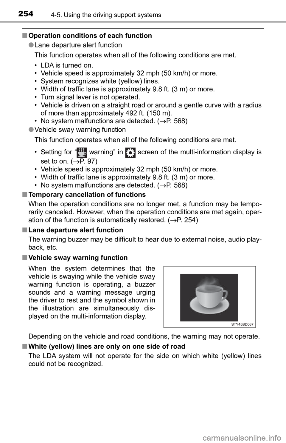
■ Vehicle sway warning function
Depending on the vehicle and road conditions, the warning may n ot operate.
■ White (yellow) lines are on ly on one side of road
The LDA system will not operate for the side on which white (ye llow) lines
could not be recognized. When the system determines that the
vehicle is swaying while the vehicle sway
warning function is operating, a buzzer
sounds and a warning message urging
the driver to rest and the symbol shown in
the illustration are simultaneously dis-
played on the multi-information display.
Page 282 of 700
2824-5. Using the driving support systems
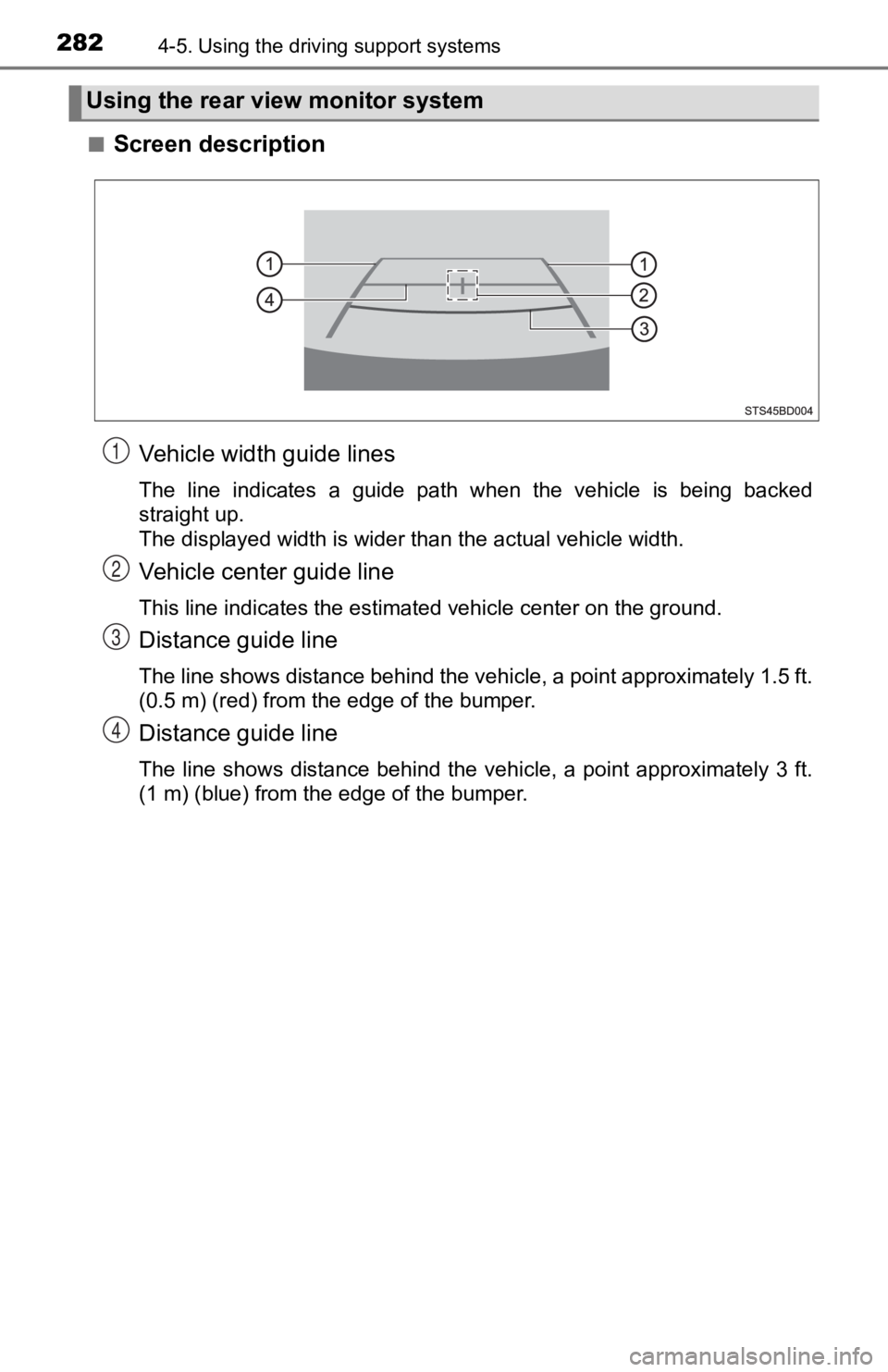
■Screen description
Vehicle width guide lines
The line indicates a guide path when the vehicle is being backe d
straight up.
The displayed width is wider than the actual vehicle width.
Vehicle center guide line
This line indicates the estimated vehicle center on the ground.
Distance guide line
The line shows distance behind the vehicle, a point approximate ly 1.5 ft.
(0.5 m) (red) from the edge of the bumper.
Distance guide line
The line shows distance behind the vehicle, a point approximate ly 3 ft.
(1 m) (blue) from the edge of the bumper.
Using the rear view monitor system
1
2
3
4
Page 284 of 700
2844-5. Using the driving support systems
■Differences between the scr een and the actual road
The distance guide lines and the vehicle width guide lines may not
actually be parallel with the div iding lines of the parking space, even
when they appear to be so. Be sure to check visually.
The distances between the vehicle width guide lines and the lef t
and right dividing lines of the parking space may not be equal, even
when they appear to be so. Be sure to check visually.
The distance guide lines give a distance guide for flat road sur-
faces. In any of the following situations, there is a margin of error
between the fixed guide lines on the screen and the actual dis-
tance/course on the road.
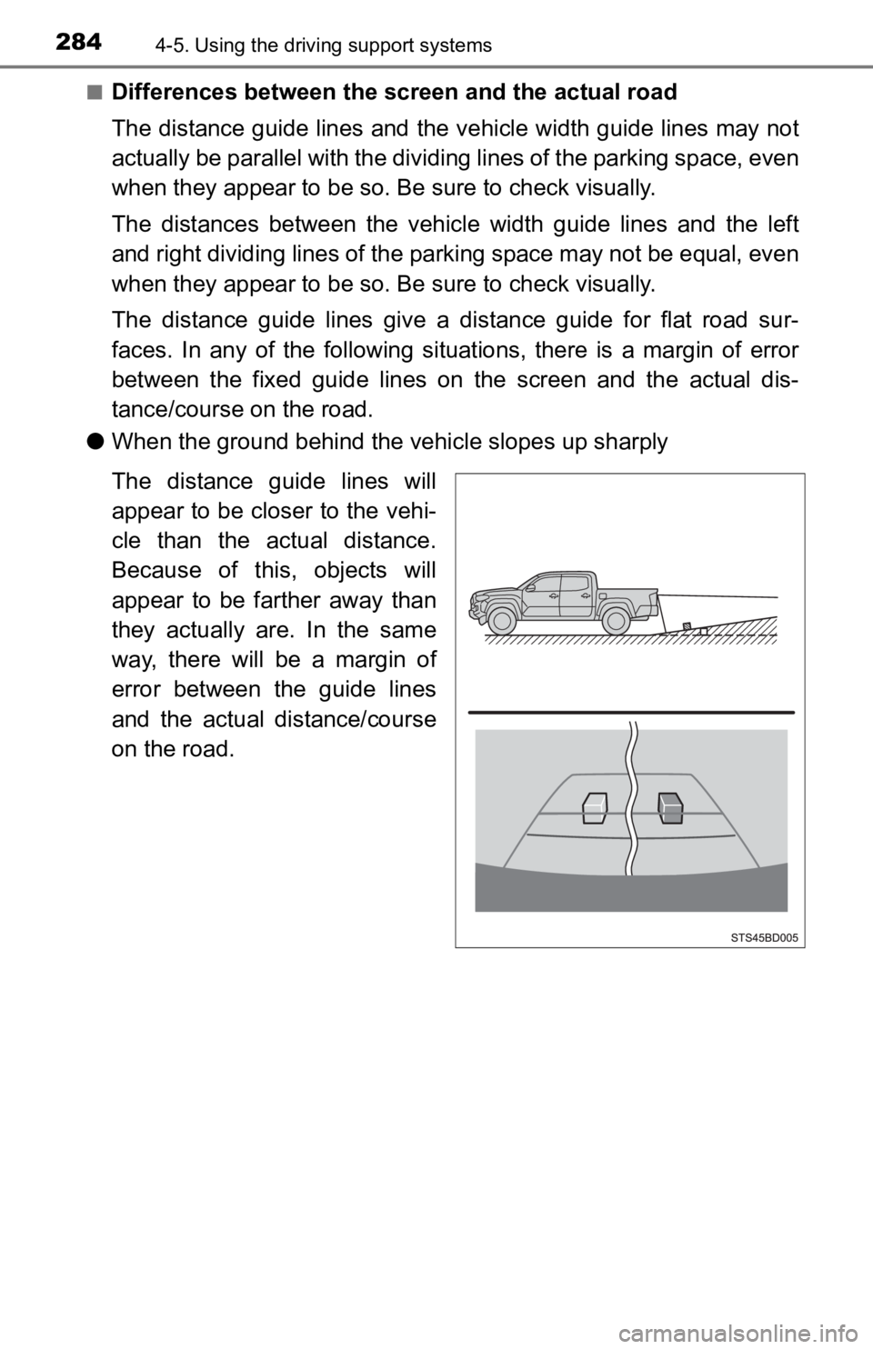
● When the ground behind the vehicle slopes up sharply
The distance guide lines will
appear to be closer to the vehi-
cle than the actual distance.
Because of this, objects will
appear to be farther away than
they actually are. In the same
way, there will be a margin of
error between the guide lines
and the actual distance/course
on the road.
Page 286 of 700
2864-5. Using the driving support systems
■When approaching thre e-dimensional objects
The distance guide lines are displayed according to flat surfac ed
objects (such as the road). It i s not possible to determine the posi-
tion of three-dimensional object s (such as vehicles) using the vehi-
cle width guide lines and distance guide lines. When approachin g a
three-dimensional object that ext ends outward (such as the flatbed
of a truck), be careful of the following.
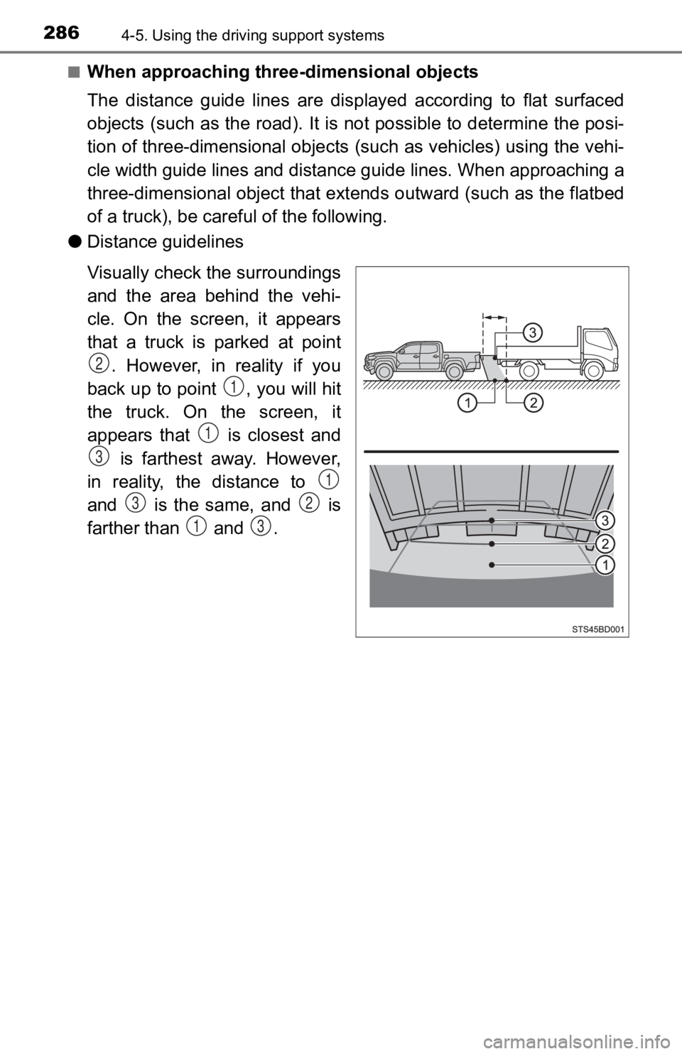
● Distance guidelines
Visually check the surroundings
and the area behind the vehi-
cle. On the screen, it appears
that a truck is parked at point
. However, in reality if you
back up to point , you will hit
the truck. On the screen, it
appears that is closest and is farthest away. However,
in reality, the distance to
and is the same, and is
farther than and .
2
1
1
3
1
32
13
Page 287 of 700
2874-5. Using the driving support systems
4
Driving
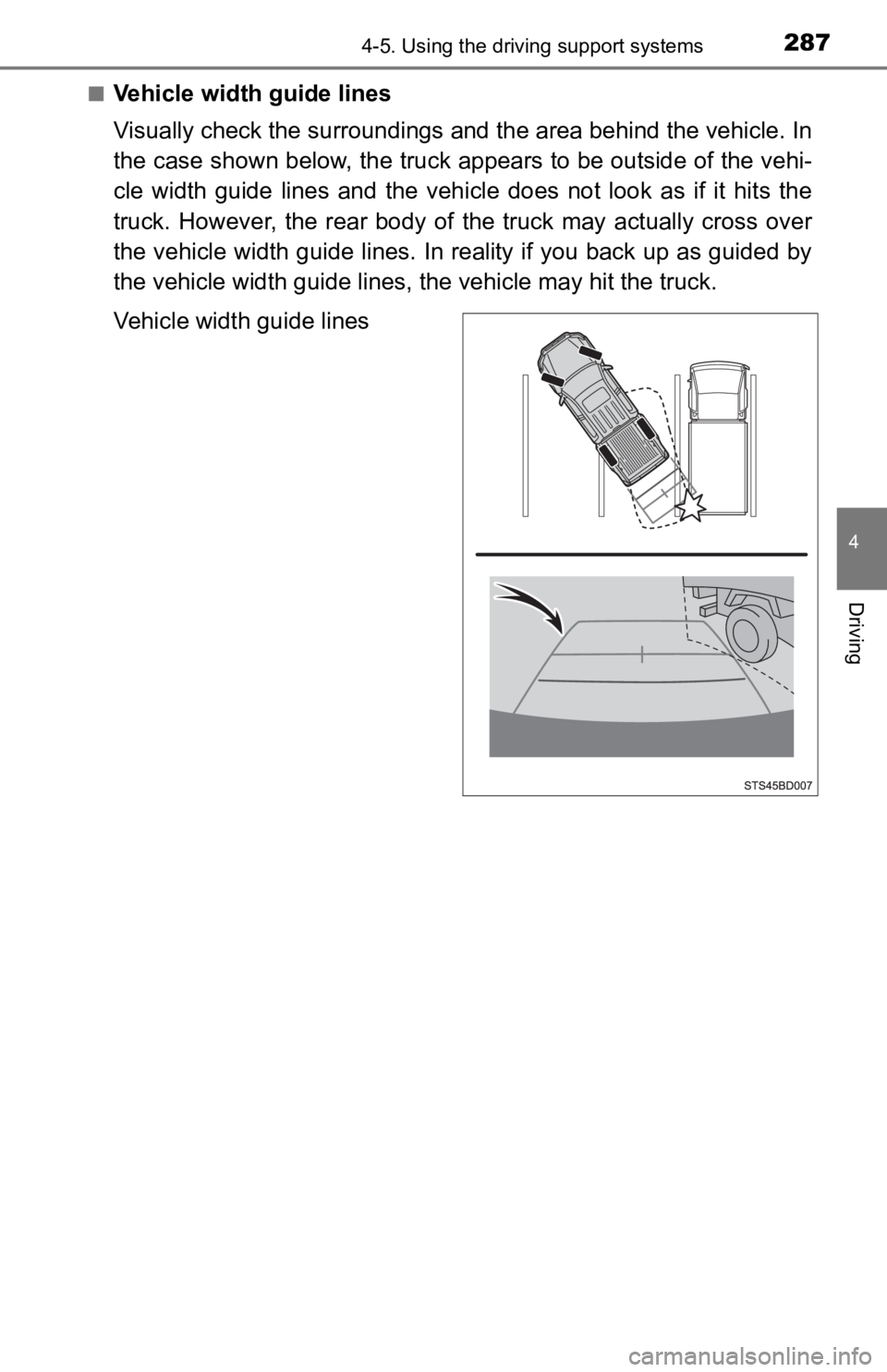
■Vehicle width guide lines
Visually check the surroundings and the area behind the vehicle. In
the case shown below, the truck appears to be outside of the ve hi-
cle width guide lines and the vehicle does not look as if it hi ts the
truck. However, the rear body of the truck may actually cross over
the vehicle width guide lines. In reality if you back up as gui ded by
the vehicle width guide lines, the vehicle may hit the truck.
Vehicle width guide lines
Page 626 of 700
6269-1. Specifications
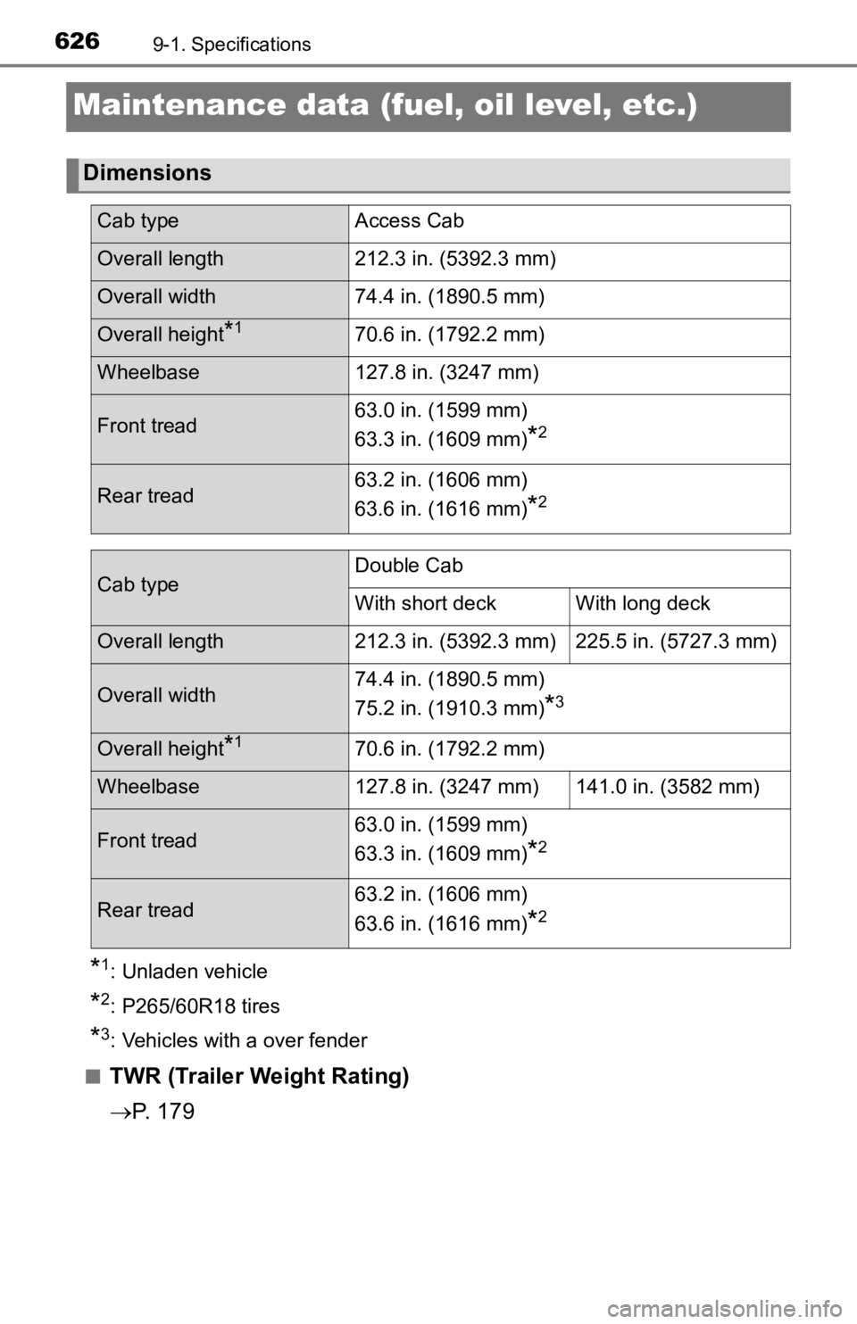
Maintenance data (fuel, oil level, etc.)
*1: Unladen vehicle
*2: P265/60R18 tires
*3: Vehicles with a over fender
■
TWR (Trailer Weight Rating)
P. 1 7 9
Dimensions
Cab type Access Cab
Overall length212.3 in. (5392.3 mm)
Overall width 74.4 in. (1890.5 mm)
Overall height*170.6 in. (1792.2 mm)
Wheelbase127.8 in. (3247 mm)
Front tread63.0 in. (1599 mm)
63.3 in. (1609 mm)*2
Rear tread63.2 in. (1606 mm)
63.6 in. (1616 mm)*2
Cab typeDouble Cab
With short deck With long deck
Overall length
212.3 in. (5392.3 mm) 225.5 in. (5727.3 mm)
Overall width74.4 in. (1890.5 mm)
75.2 in. (1910.3 mm)*3
Overall height*170.6 in. (1792.2 mm)
Wheelbase
127.8 in. (3247 mm) 141.0 in. (3582 mm)
Front tread63.0 in. (1599 mm)
63.3 in. (1609 mm)*2
Rear tread63.2 in. (1606 mm)
63.6 in. (1616 mm)*2
Page 645 of 700
6459-1. Specifications
9
Vehicle specifications
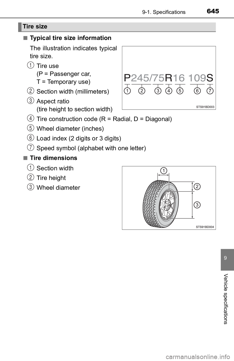
■Typical tire size information
The illustration indicates typical
tire size.
Tire use
(P = Passenger car,
T = Temporary use)
Section widt h (millimeters)
Aspect ratio
(tire height to section width)
Tire construction code ( R = Radial, D = Diagonal)
Wheel diameter (inches)
Load index (2 digits or 3 digits)
Speed symbol (alphabet with one letter)
■Tire dimensions
Section width
Tire height
Wheel diameter
Tire size
1
2
3
4
5
6
7
1
2
3
Page 647 of 700
6479-1. Specifications
9
Vehicle specifications
This information has been prepared in accordance with regulations
issued by the National Highway Tr affic Safety Administration of the
U.S. Department of Transportation.
It provides the purchasers and/or prospective purchasers of Toyota
vehicles with info rmation on uniform ti re quality grading.
Your Toyota dealer will help answer any questions you may have as
you read this information.
■DOT quality grades
All passenger vehicle tires must conform to Federal Safety Requ ire-
ments in addition to these grades. Quality grades can be found
where applicable on the tire sidewall between tread shoulder an d
maximum section width.
For example: Treadwear 200 Traction AA Temperature A
■Treadwear
The treadwear grade is a comparative rating based on the wear
rate of the tire when tested under controlled conditions on a s peci-
fied government t est course.
For example, a tire graded 150 would wear one and a half (1 - 1 /2)
times as well on the governmen t course as a tire graded 100.
The relative performance of tires depends upon the actual condi -
tions of their use. Performance ma y differ significantly from the norm
due to variations in driving habits, service practices and diff erences
in road characteristics and climate.
■Traction AA, A, B, C
The traction grades, from highest to lowest, are AA, A, B and C ,
and they represent the tire’s ability to stop on wet pavement a s
measured under controlled conditions on specified government te st
surfaces of asphalt and concrete.
A tire marked C may have p oor traction performance.
Warning: The traction grade assigned to this tire is based on b raking
(straight ahead) traction tests and does not include cornering (turn-
ing) traction.
Uniform Tire Quality Grading
Page 650 of 700
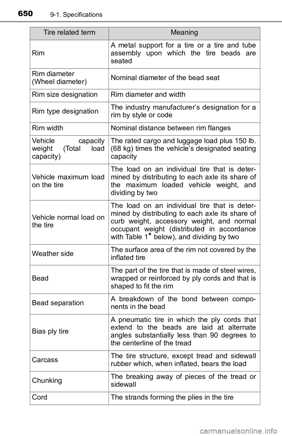
6509-1. Specifications
Rim
A metal support for a tire or a tire and tube
assembly upon which the tire beads are
seated
Rim diameter
(Wheel diameter)Nominal diameter of the bead seat
Rim size designationRim diameter and width
Rim type designationThe industry manufacturer’s designation for a
rim by style or code
Rim widthNominal distance between rim flanges
Vehicle capacity
weight (Total load
capacity)The rated cargo and l uggage load plus 150 lb.
(68 kg) times the vehicle’s designated seating
capacity
Vehicle maximum load
on the tire
The load on an individual tire that is deter-
mined by distributing to each axle its share of
the maximum loaded vehicle weight, and
dividing by two
Vehicle normal load on
the tire
The load on an individual tire that is deter-
mined by distributing to each axle its share of
curb weight, accessory weight, and normal
occupant weight (distributed in accordance
with Table 1
* below), and dividing by two
Weather sideThe surface area of the rim not covered by the
inflated tire
Bead
The part of the tire that is made of steel wires,
wrapped or reinforced by ply cords and that is
shaped to fit the rim
Bead separationA breakdown of the bond between compo-
nents in the bead
Bias ply tire
A pneumatic tire in which the ply cords that
extend to the beads are laid at alternate
angles substantially less than 90 degrees to
the centerline of the tread
CarcassThe tire structure, except tread and sidewall
rubber which, when inflated, bears the load
ChunkingThe breaking away of pieces of the tread or
sidewall
CordThe strands forming th e plies in the tire
Tire related termMeaning
Page 652 of 700
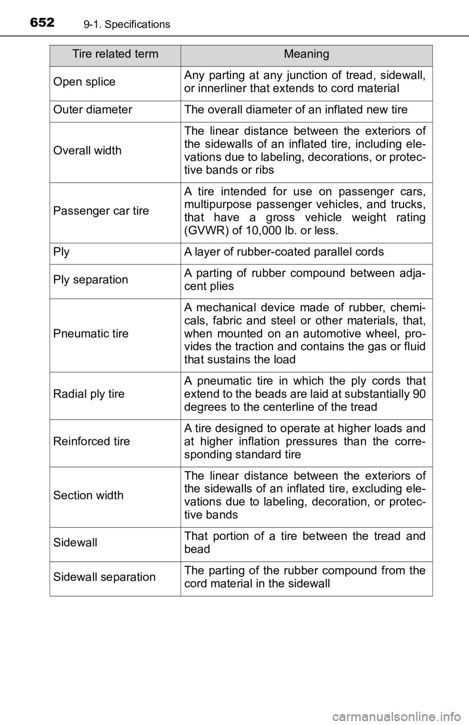
6529-1. Specifications
Open spliceAny parting at any junction of tread, sidewall,
or innerliner that extends to cord material
Outer diameterThe overall diameter of an inflated new tire
Overall width
The linear distance between the exteriors of
the sidewalls of an inflated tire, including ele-
vations due to labeling, decorations, or protec-
tive bands or ribs
Passenger car tire
A tire intended for use on passenger cars,
multipurpose passenger vehicles, and trucks,
that have a gross vehicle weight rating
(GVWR) of 10,000 lb. or less.
PlyA layer of rubber-coated parallel cords
Ply separationA parting of rubber compound between adja-
cent plies
Pneumatic tire
A mechanical device made of rubber, chemi-
cals, fabric and steel or other materials, that,
when mounted on an automotive wheel, pro-
vides the traction and co ntains the gas or fluid
that sustains the load
Radial ply tire
A pneumatic tire in which the ply cords that
extend to the beads are laid at substantially 90
degrees to the centerline of the tread
Reinforced tire
A tire designed to operate at higher loads and
at higher inflation pressures than the corre-
sponding standard tire
Section width
The linear distance between the exteriors of
the sidewalls of an inflated tire, excluding ele-
vations due to labeling, decoration, or protec-
tive bands
SidewallThat portion of a tire between the tread and
bead
Sidewall separationThe parting of the rubber compound from the
cord material in the sidewall
Tire related termMeaning