turn signal TOYOTA TACOMA 2020 (in English) User Guide
[x] Cancel search | Manufacturer: TOYOTA, Model Year: 2020, Model line: TACOMA, Model: TOYOTA TACOMA 2020Pages: 608, PDF Size: 11.6 MB
Page 262 of 608
2624-5. Using the driving support systems
■Operation conditio ns of each function
● Lane departure alert function
This function operates when all of the following conditions are met.
• LDA is turned on.
• Vehicle speed is approximately 32 mph (50 km/h) or more.
• System recognizes white (yellow) lines.
• Width of traffic lane is approximately 9.8 ft. (3 m) or more.
• Turn signal lever is not operated.
• Vehicle is driven on a straight road or around a gentle curve with a radius
of more than approximately 492 ft. (150 m).
• No system malfunctions are detected. ( P. 475)
● Vehicle sway warning function
This function operates when all of the following conditions are met.
• Setting for “ warning” in screen of the multi-information display is set to on. ( P. 105)
• Vehicle speed is approximately 32 mph (50 km/h) or more.
• Width of traffic lane is approximately 9.8 ft. (3 m) or more.
• No system malfunctions are detected. ( P. 475)
■ Temporary cancellation of functions
When the operation conditions are no longer met, a function may be tempo-
rarily canceled. However, when the operation conditions are met again, oper-
ation of the function is automatically restored. ( P. 262)
■ Lane departure alert function
The warning buzzer may be difficult to hear due to external noi se, audio play-
back, etc.
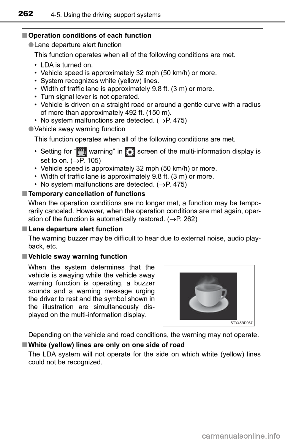
■ Vehicle sway warning function
Depending on the vehicle and road conditions, the warning may n ot operate.
■ White (yellow) lines are on ly on one side of road
The LDA system will not operate for the side on which white (ye llow) lines
could not be recognized. When the system determines that the
vehicle is swaying while the vehicle sway
warning function is operating, a buzzer
sounds and a warning message urging
the driver to rest and the symbol shown in
the illustration are simultaneously dis-
played on the multi-information display.
Page 289 of 608
2894-5. Using the driving support systems
4
Driving
BSM (Blind Spot Monitor)
The Blind Spot Monitor is a system that has 2 functions;
● The Blind Spot Monitor function
Assists the driver in making t he decision when changing lanes
● The Rear Cross Traffic Alert function
Assists the driver when backing up
These functions use same sensors.
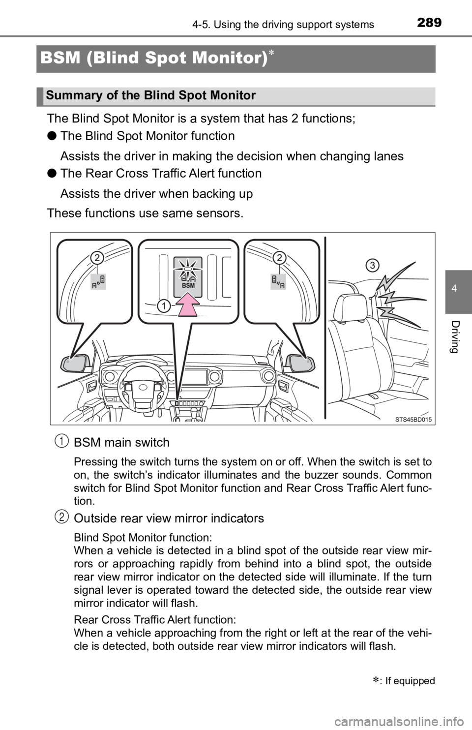
BSM main switch
Pressing the switch turns the system on or off. When the switch is set to
on, the switch’s indicator illuminates and the buzzer sounds. C ommon
switch for Blind Spot Monitor function and Rear Cross Traffic A lert func-
tion.
Outside rear view mirror indicators
Blind Spot Monitor function:
When a vehicle is detected in a blind spot of the outside rear view mir-
rors or approaching rapidly from behind into a blind spot, the outside
rear view mirror indicator on the detected side will illuminate. If the turn
signal lever is operated toward the detected side, the outside rear view
mirror indicator will flash.
Rear Cross Traffic Alert function:
When a vehicle approaching from the right or left at the rear of the vehi-
cle is detected, both outside rear view mirror indicators will flash.
: If equipped
Summary of the Blind Spot Monitor
1
2
Page 387 of 608
3875-4. Other interior features
5
Interior features
■Reprogramming a single HomeLink® button
When the following procedure is performed, buttons which alread y
have devices registered to them can be overwritten:
With one hand, press and hold the desired HomeLink
® button.
When the HomeLink
® indicator starts flas hing orange, release
the HomeLink® button and perform “Programming the Home-
Link®” (it takes 20 seconds for the HomeLink® indicator to
start flashing).
Press the appropriate HomeLink
® button. The HomeLink® indicator
light should turn on.
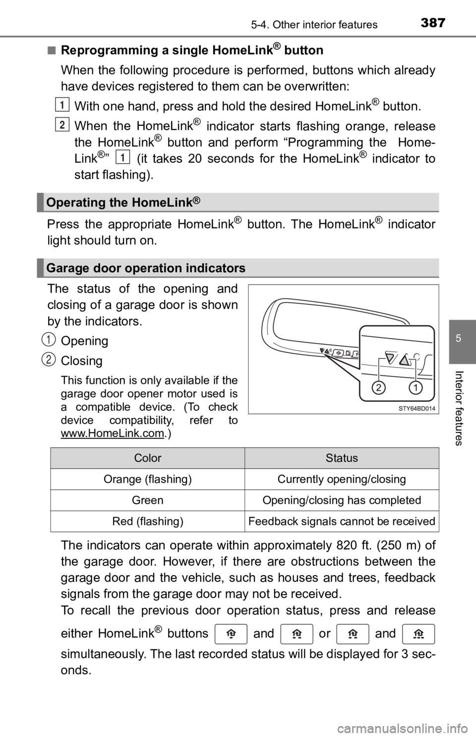
The status of the opening and
closing of a garage door is shown
by the indicators.
Opening
Closing
This function is only available if the
garage door opener motor used is
a compatible device. (To check
device compatibility, refer to
www.HomeLink.com
.)
The indicators can operate within approximately 820 ft. (250 m) of
the garage door. However, if there are obstructions between the
garage door and the vehicle, such as houses and trees, feedback
signals from the garage door may not be received.
To recall the previous door operation status, press and release
either HomeLink
® buttons and or and
simultaneously. The last recorded status will be displayed for 3 sec-
onds.
Operating the HomeLink®
Garage door operation indicators
1
2
1
1
2
ColorStatus
Orange (flashing)Currently opening/closing
GreenOpening/closing has completed
Red (flashing)Feedback signals cannot be received
Page 427 of 608
4276-3. Do-it-yourself maintenance
6
Maintenance and care
■How to initialize the tire pressure warning systemVehicles without a smart key system:
Park the vehicle in a safe plac e and turn the engine switch to the
“LOCK” position.
Vehicles with a smart key system:
Park the vehicle in a safe place and turn the engine switch off .
Initialization cannot be performed while the vehicle is moving.
Adjust the tire inflation pressure to the specified cold tire i nflation
pressure level. ( P. 543)
Make sure to adjust the tire pre ssure to the specified cold tire infla-
tion pressure level. The tire pressure warning system will oper ate
based on this pr essure level.
Vehicles without a smart key system:
Turn the engine switch t o the “ON” position.
Vehicles with a smart key system:
Turn the engine switch to IGNITION ON mode.
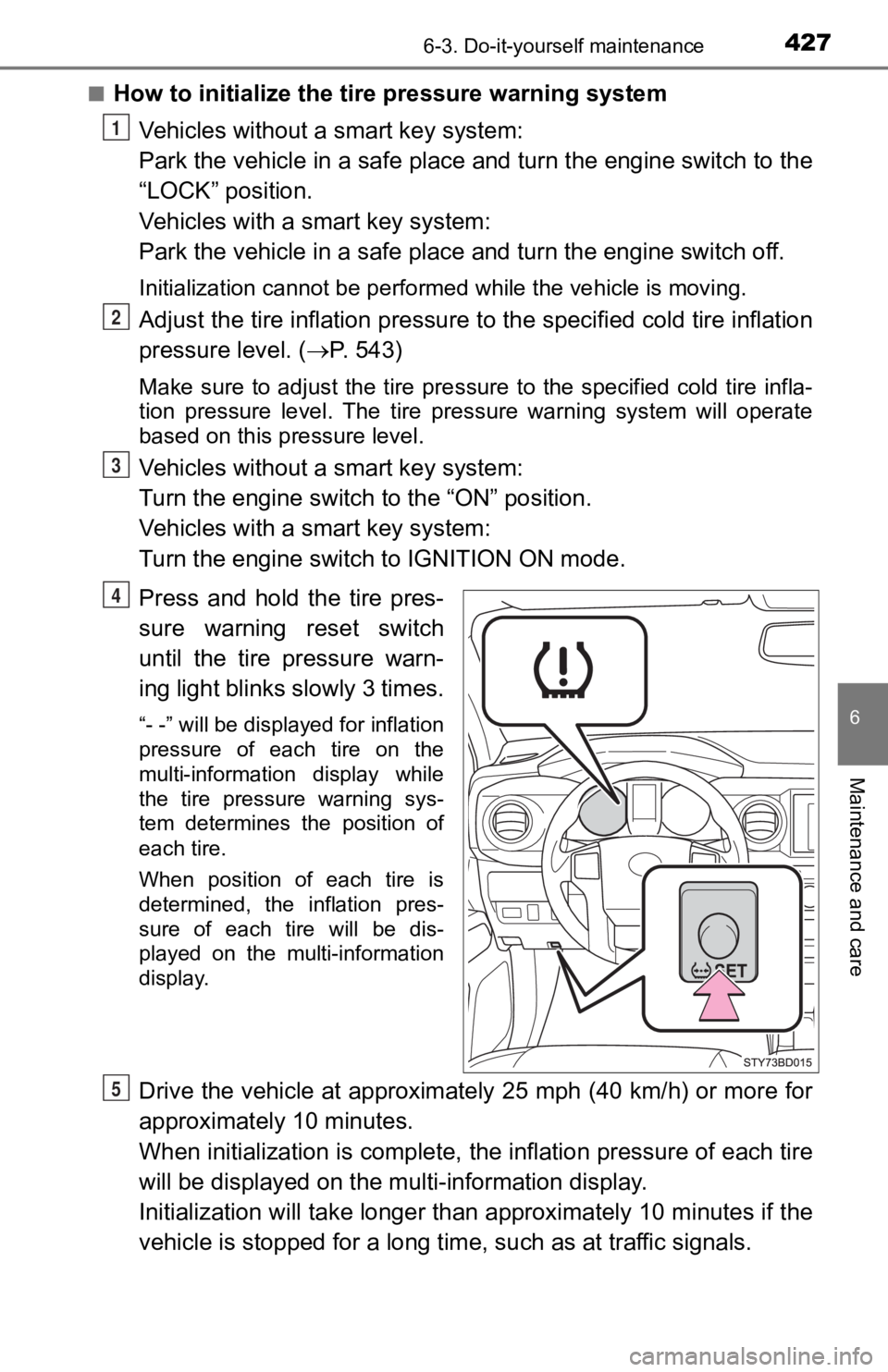
Press and hold the tire pres-
sure warning reset switch
until the tire pressure warn-
ing light blinks slowly 3 times.
“- -” will be displayed for inflation
pressure of each tire on the
multi-information display while
the tire pressure warning sys-
tem determines the position of
each tire.
When position of each tire is
determined, the inflation pres-
sure of each tire will be dis-
played on the multi-information
display.
Drive the vehicle at approximately 25 mph (40 km/h) or more for
approximately 10 minutes.
When initialization is complete, the inflation pressure of each tire
will be displayed on the mu lti-information display.
Initialization will ta ke longer than approxi mately 10 minutes if the
vehicle is stopped for a long time, such as at traffic signals.
1
2
3
4
5
Page 449 of 608
4496-3. Do-it-yourself maintenance
6
Maintenance and care
Light bulbs
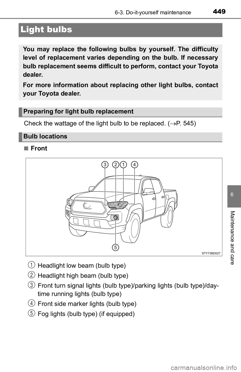
Check the wattage of the light bulb to be replaced. ( P. 545)
■Front
You may replace the following bul bs by yourself. The difficulty
level of replacement varies depending on the bulb. If necessary
bulb replacement seems difficult to perform, contact your Toyot a
dealer.
For more information about replacing other light bulbs, contact
your Toyota dealer.
Preparing for light bulb replacement
Bulb locations
Headlight low beam (bulb type)
Headlight high beam (bulb type)
Front turn signal lights (bulb type)/parking lights (bulb type) /day-
time running lights (bulb type)
Front side marker lights (bulb type)
Fog lights (bulb type) (if equipped)1
2
3
4
5
Page 450 of 608
4506-3. Do-it-yourself maintenance
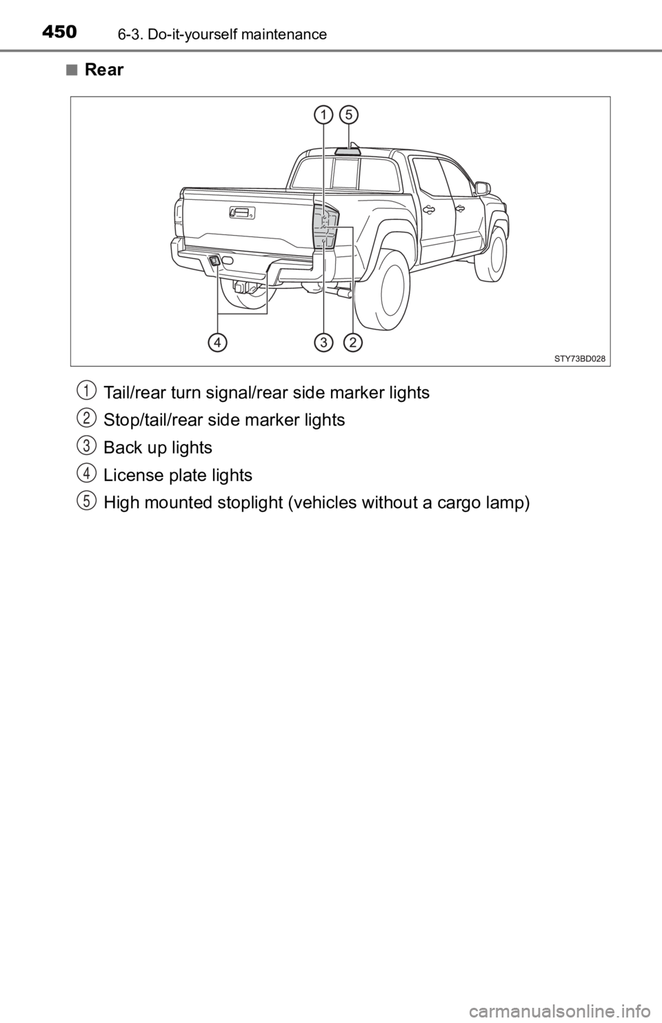
■Rear
Tail/rear turn signal/rear side marker lights
Stop/tail/rear side marker lights
Back up lights
License plate lights
High mounted stoplight (vehic les without a cargo lamp)1
2
3
4
5
Page 454 of 608
4546-3. Do-it-yourself maintenance
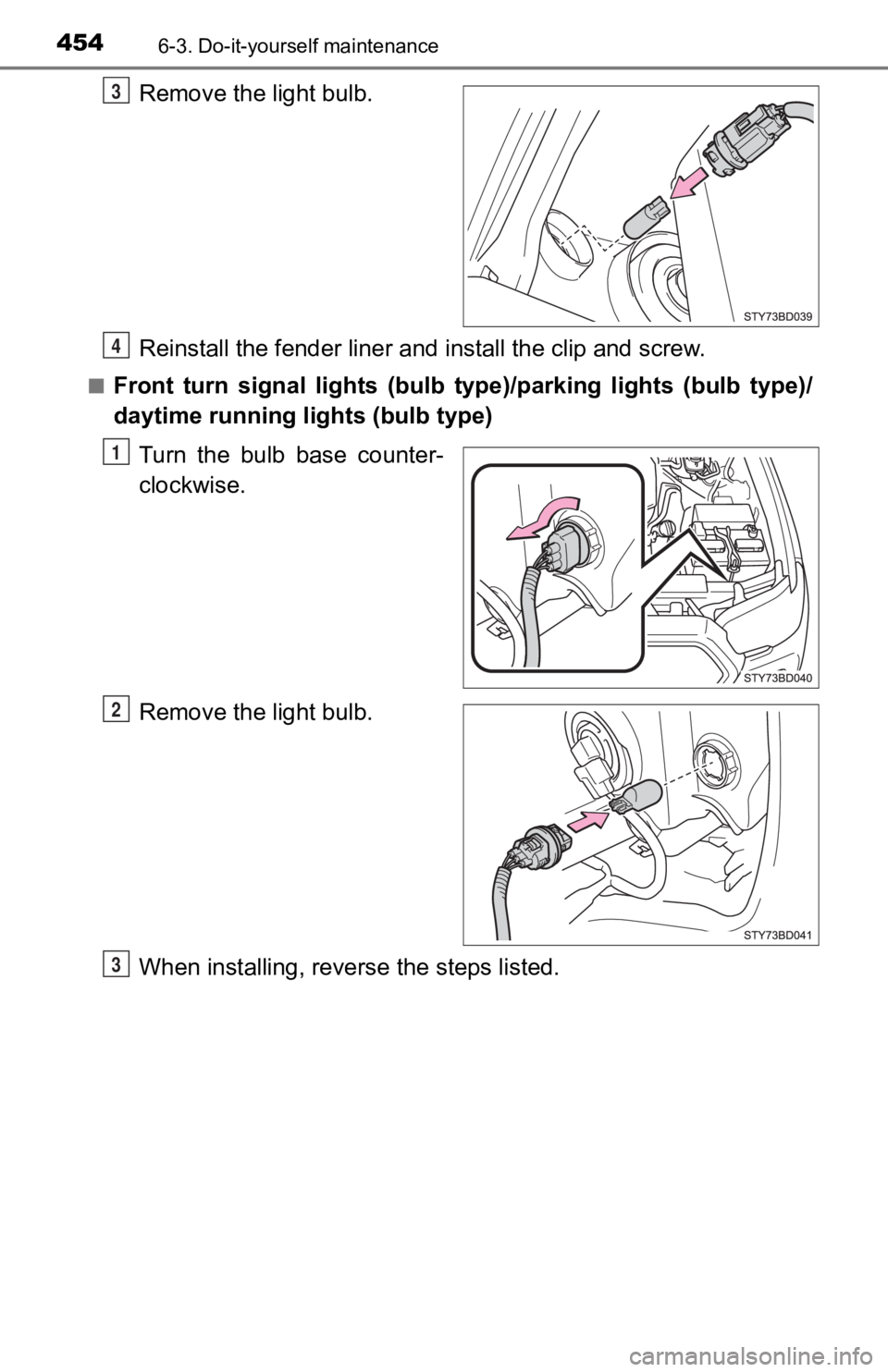
Remove the light bulb.
Reinstall the fender liner and install the clip and screw.
■Front turn signal lights (bulb ty pe)/parking lights (bulb type)/
daytime running li ghts (bulb type)
Turn the bulb base counter-
clockwise.
Remove the light bulb.
When installing, reverse the steps listed.
3
4
1
2
3
Page 457 of 608
4576-3. Do-it-yourself maintenance
6
Maintenance and care
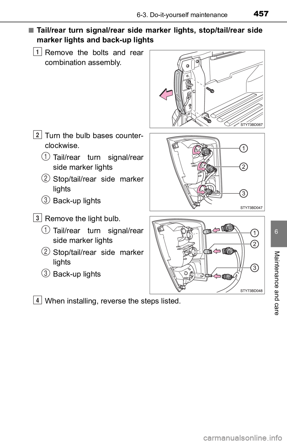
■Tail/rear turn signal/rear side marker lights, stop/tail/rear side
marker lights and back-up lights
Remove the bolts and rear
combination assembly.
Turn the bulb bases counter-
clockwise.Tail/rear turn signal/rear
side marker lights
Stop/tail/rear side marker
lights
Back-up lights
Remove the light bulb. Tail/rear turn signal/rear
side marker lights
Stop/tail/rear side marker
lights
Back-up lights
When installing, reverse the steps listed.
1
2
1
2
3
3
1
2
3
4
Page 460 of 608

4606-3. Do-it-yourself maintenance
■Replacing the following bulbs
If any of the lights listed below has burnt out, have it replaced by
your Toyota dealer.
● Headlights low beam (LED type)
● Headlights high beam (LED type)
● Front turn signal lights (LED type)
● Front side marker lights (LED type)
● Fog lights (LED type)
● Parking lights (LED type)
● Daytime running lights (LED type)
● High mounted stoplight (vehicles with cargo lamp)
● Side turn signal lights (if equipped)
■LED Lights
The side turn signal lights (if equipped), parking lights (LED type), daytime
running light (LED type) and, high mounted stoplight (vehicles with cargo
lamp) consist of a number of LEDs. If any of the LEDs burn out, take your
vehicle to your Toyota dealer to have the light replaced.
■ Condensation build-up on the inside of the lens
Toyota lamps are vented to all surrounding environmental conditions and may
experience temporary condensation build-up that is visible from outside of the
lamp. Condensation and fogging does not indicate a malfunction of the lamp
assembly. It is normal for condensation to improve and disappea r after time
and normal driving use. Visible pools of water or large droplets are a sign of a
lamp in which the seal has malfunctioned. If this is the case o r condensation
and fogging remain after long periods of time, contact your Toyota dealer for
more information.
Page 464 of 608
4647-1. Essential information
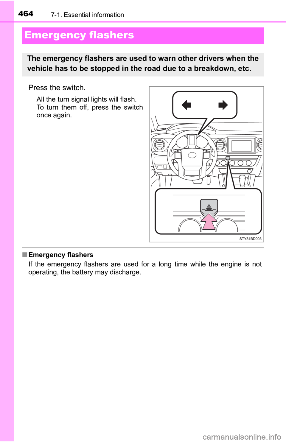
Emergency flashers
Press the switch.
All the turn signal lights will flash.
To turn them off, press the switch
once again.
■Emergency flashers
If the emergency flashers are used for a long time while the en gine is not
operating, the battery may discharge.
The emergency flashers are used to warn other drivers when the
vehicle has to be stopped in the road due to a breakdown, etc.