power steering TOYOTA tC 2013 (in English) User Guide
[x] Cancel search | Manufacturer: TOYOTA, Model Year: 2013, Model line: tC, Model: TOYOTA tC 2013Pages: 484, PDF Size: 9.41 MB
Page 338 of 484

338 4-3. Do-it-yourself maintenance
tC_OM_OM21050U_(U)
9 H-LP MAIN 50 AH-LP LH-LO, H-LP RH-LO, H-LP
LH-HI, H-LP RH-HI, headlights,
daytime running light system
10 SPARE 10 A Spare fuse
11 SPARE 20 A Spare fuse
12 SPARE 30 A Spare fuse
13 H-LP RH-HI 10 A Right hand headlight (high beam),
gauges and meters
14 H-LP LH-HI 10 A Left hand headlight (high beam)
15 H-LP RH-LO 10 A Right hand headlight (low beam),
gauges and meters
16 H-LP LH-LO 10 A Left hand headlight (low beam)
17 ETCS 10 A Multiport fuel injection system/
sequential multiport fuel injection
system
18 HAZ 10 A Turn signal lights, emergency
flashers, gauges and meters
19 ALT-S 7.5 A Charging system
20 AM2 NO.2
*7.5 A Power management system
21 AM2 30 A IG2 NO.2, starting system
22 STRG LOCK
*20 A Steering lock system
23 AMP 30 A Audio system
24 MIR HTR 10 A Outside rear view mirror defoggers,
multiport fuel injection system/
sequential multiport fuel injection
system
FuseAmpereCircuit
Page 339 of 484

339
4-3. Do-it-yourself maintenance
4
Maintenance and care
tC_OM_OM21050U_(U)
25 ECU-B NO.2 10 A
Automatic transmission, power
windows, clock, smart key system,
wireless remote control, front pas-
senger occupant classification sys-
tem
26 ECU-B 10 ABody ECU, gauges and meters,
steering sensor, wireless remote
control, smart key system
27 RAD NO.1 15 A Audio system
28 DOME 10 AInterior light, personal light, lug-
gage compartment light
29 STOP 10 AMultiport fuel injection system/
sequential multiport fuel injection
system, ABS, VSC, automatic
transmission, shift lock system,
stop lights, high mounted stoplight,
power management system
FuseAmpereCircuit
Page 341 of 484

341
4-3. Do-it-yourself maintenance
4
Maintenance and care
tC_OM_OM21050U_(U)
■
Under the driver’s side instrument panel
FuseAmpereCircuit
1S/ROOF30 AMoon roof
2 FOG FR 15 A No circuit
3 FOG RR 7.5 A No circuit
4 AM1 5 A Starting system, body ECU
5 OBD 7.5 A On-board diagnosis system
6 D/L 20 A Power door lock system
7 DOOR FR 20 A Power windows
8 WASHER RR 7.5 A Rear window washer
9 WASHER FR 10 A Windshield washer
10 WIP RR 15 A Rear window wiper 11 WIP FR 30 A Windshield wipers
12 PWR OUTLET 15 A Power outlet
13 ECU-IG1 NO.1 5 A Electric power steering, shift lock
system, moon roof, tire pressure
warning system, charging system,
paddle shift switches
Page 343 of 484

343
4-3. Do-it-yourself maintenance
4
Maintenance and care
tC_OM_OM21050U_(U)
■
Driver’s side instrument panel
21 S/HTR FR 10 ASeat heater (front passenger’s
side)
22 IG2 NO.2 7.5 A Starting system
23 BKUP LP 7.5 ABack-up light, automatic transmis-
sion, multiport fuel injection sys-
tem/sequential multiport fuel
injection system
24 ECU-IG1 NO.2 5 A Body ECU, ABS, VSC, steering
sensor, yaw rate & G sensor
25 ECU-IG1 NO.3 5 A Turn signal lights, emergency
flashers
26 HTR-IG 7.5 A Air conditioning system
FuseAmpereCircuit
1DOOR FL30 APower windows
FuseAmpereCircuit
Page 363 of 484

5
When trouble arises
363
5-1. Essential information
tC_OM_OM21050U_(U)
CAUTION
■
Caution while towing
● Use extreme caution when towing the vehicle.
Avoid sudden starts or erratic driving maneuvers which place excessive
stress on the emergency towing eyelets and the cables or chains. Always
be cautious of the surroundings and other vehicles while towing.
● Vehicles without a smart key system:
Do not turn the engine switch to the “LOCK” position or remove the\
key.
Vehicles with a smart key system:
Do not turn the “ENGINE START STOP” switch off.
Doing so will lock the steering wheel and prevent operation, possibly caus-
ing an accident and resulting in death or serious injury.
● If the engine is not running, the power assist for the brakes and steering
will not function, making steering and braking more difficult.
■ Installing towing eyelets to the vehicle
Make sure that towing eyelets are installed securely.
If not securely installed, towing eyelets may come loose during towing. This
may lead to accidents that cause serious injury or even death.
Page 370 of 484
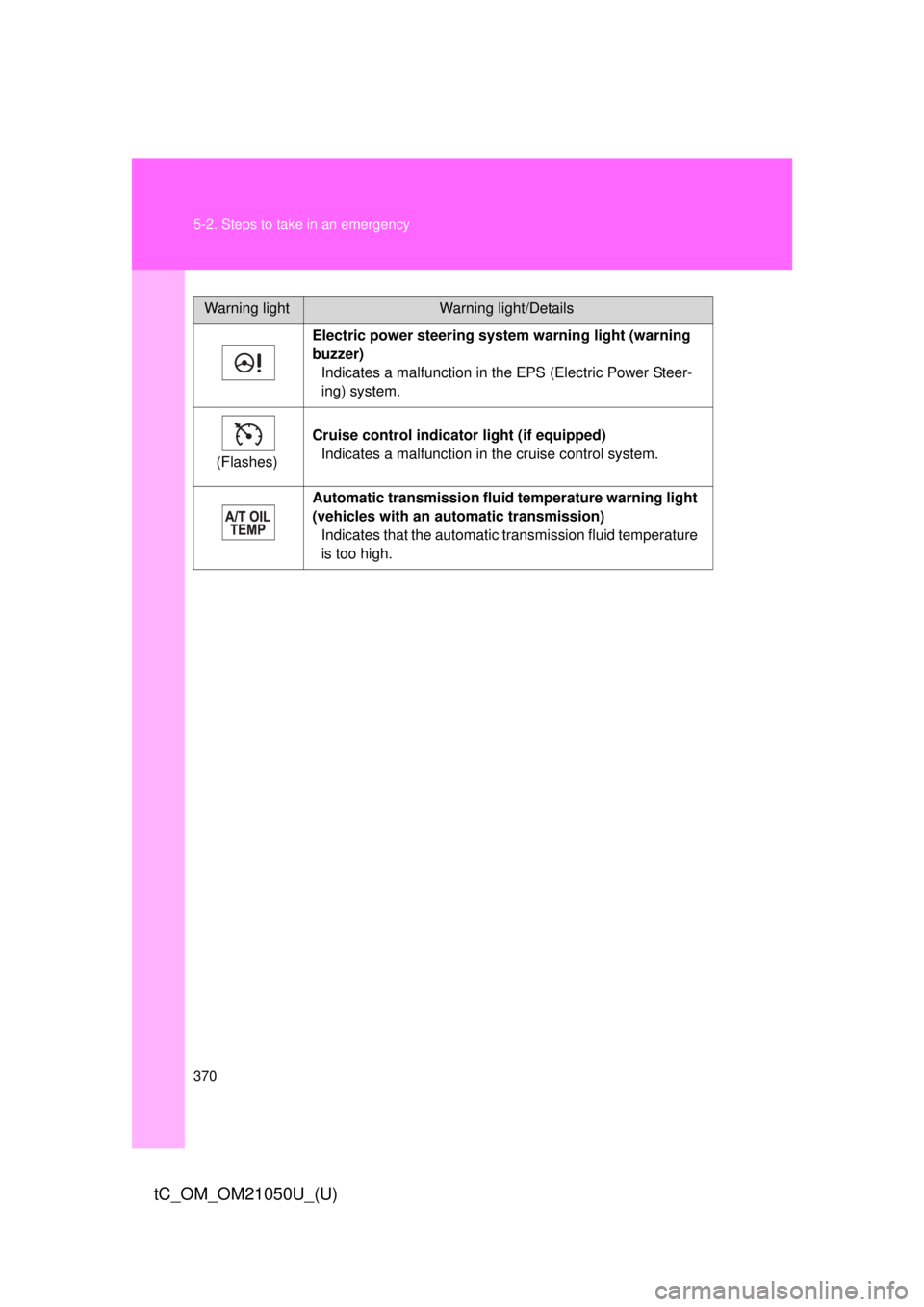
370 5-2. Steps to take in an emergency
tC_OM_OM21050U_(U)
Electric power steering system warning light (warning
buzzer)Indicates a malfunction in the EPS (Electric Power Steer-
ing) system.
(Flashes) Cruise control indicator
light (if equipped)
Indicates a malfunction in the cruise control system.
Automatic transmission flui d temperature warning light
(vehicles with an auto matic transmission)
Indicates that the automatic transmission fluid temperature
is too high.
Warning lightWarning light/Details
Page 378 of 484

378 5-2. Steps to take in an emergency
tC_OM_OM21050U_(U)
■SRS warning light
This warning light system monitors the airbag sensor assembly, front airbag
sensors, side impact sensors (front), side impact sensors (rear), side impact
sensors (front door), driver’s seat position sensor, driver’s seat belt buckle
switch, front passenger occupant classification system, “AIR BAG ON” indi-
cator light, “AIR BAG OFF” indicator light, front passenger’s seat belt buckle
switch, seat belt pretensioner assemblies, airbags, interconnecting wiring
and power sources. ( P. 106)
■ Front passenger detection sensor, passenger seat belt reminder and
warning buzzer
● If luggage is placed on the front passenger seat, the front passenger
detection sensor may cause the warning light to flash and the warning
buzzer to sound even if a passenger is not sitting in the seat.
● If a cushion is placed on the seat, the sensor may not detect a passen-
ger, and the warning light may not operate properly.
■ Electric power steering system warning light (warning buzzer)
The electric power steering system warning light may come on and warning
buzzer may sound when the voltage is low or drops.
■ If the malfunction indicator lamp comes on while driving
First check the following:
● Is the fuel tank empty?
If it is, fill the fuel tank immediately.
● Is the fuel tank cap loose?
If it is, tighten it securely.
The malfunction indicator lamp will go off after taking driving trips.
If the malfunction indicator lamp does not go off even after several trips, con-
tact your Scion dealer as soon as possible.
Page 382 of 484

382 5-2. Steps to take in an emergency
tC_OM_OM21050U_(U)
CAUTION
■When the electric power steerin g system warning light comes on
The steering wheel may become extremely heavy.
If the steering wheel becomes heavier than usual when operating, hold
firmly and operate using more force than usual.
■
If the tire pressure warning light comes on (U.S.A. only)
Be sure to observe the following precautions. Failure to do so could
cause a loss of vehicle control and result in death or serious injury.
●Stop your vehicle in a safe place as soon as possible. Adjust the tire
inflation pressure immediately.
●If the tire pressure warning light comes on even after tire inflation pres-
sure adjustment, it is pr obable that you have a flat tire. Check the tires.
If a tire is flat, change it with th e spare tire and have the flat tire
repaired by the nearest Scion dealer.
●Avoid abrupt maneuvering and braking. If the vehicle tires deteriorate,
you could lose control of the steering wheel or the brakes.
■If a blowout or sudden air leakage should occur (U.S.A. only)
The tire pressure warning syste m may not activate immediately.
Page 419 of 484

5
When trouble arises
419
5-2. Steps to take in an emergency
tC_OM_OM21050U_(U)
CAUTION
■
If the engine has to be turned off while driving
● Power assist for the brakes and steering wheel will be lost, making the
brake pedal harder to depress and the steering wheel heavier to turn.
Decelerate as much as possible before turning off the engine.
● Vehicles without a smart key system: Never attempt to remove the key, as
doing so will lock the steering wheel.
Vehicles with a smart key sys-
tem: To stop the engine, press
and hold the “ENGINE START
STOP” switch for 3 consecu-
tive seconds or more, or press
it briefly 3 times or more in
succession.
Stop the vehicle in a safe place by the road.STEP 4
Press and hold for 3 seconds or more, or press briefly 3 times or more
STEP 5
Page 443 of 484

443
6-1. Specifications
6
Vehicle specifications
tC_OM_OM21050U_(U)
Glossary of tire terminology
Tire related termMeaning
Cold tire inflation pres-
sure Tire pressure when the vehicle has been
parked for three hours or more, or has not
been driven more than 1 mile or 1.5 km under
that condition
Maximum inflation
pressure The maximum cold inflated
pressure to which a
tire may be inflated, s hown on the sidewall of
the tire
Recommended infla-
tion pressure Cold tire inflation pressure recommended by a
manufacturer
Accessory weight The combined weight (in excess of those stan-
dard items which may be replaced) of auto-
matic transmission, power steering, power
brakes, power windows, power seats, radio
and heater, to the extent that these items are
available as factory-installed equipment
(whether installed or not)
Curb weight The weight of a motor vehicle with standard
equipment, including the maximum capacity of
fuel, oil and coolant, and if so equipped, air
conditioning and additional weight optional
engine