boot TOYOTA TERCEL 1985 Repair Manual
[x] Cancel search | Manufacturer: TOYOTA, Model Year: 1985, Model line: TERCEL, Model: TOYOTA TERCEL 1985Pages: 885, PDF Size: 64.52 MB
Page 484 of 885
FA.4FRONT AXLE AND SUSPENSION - Front Wheel Alignment
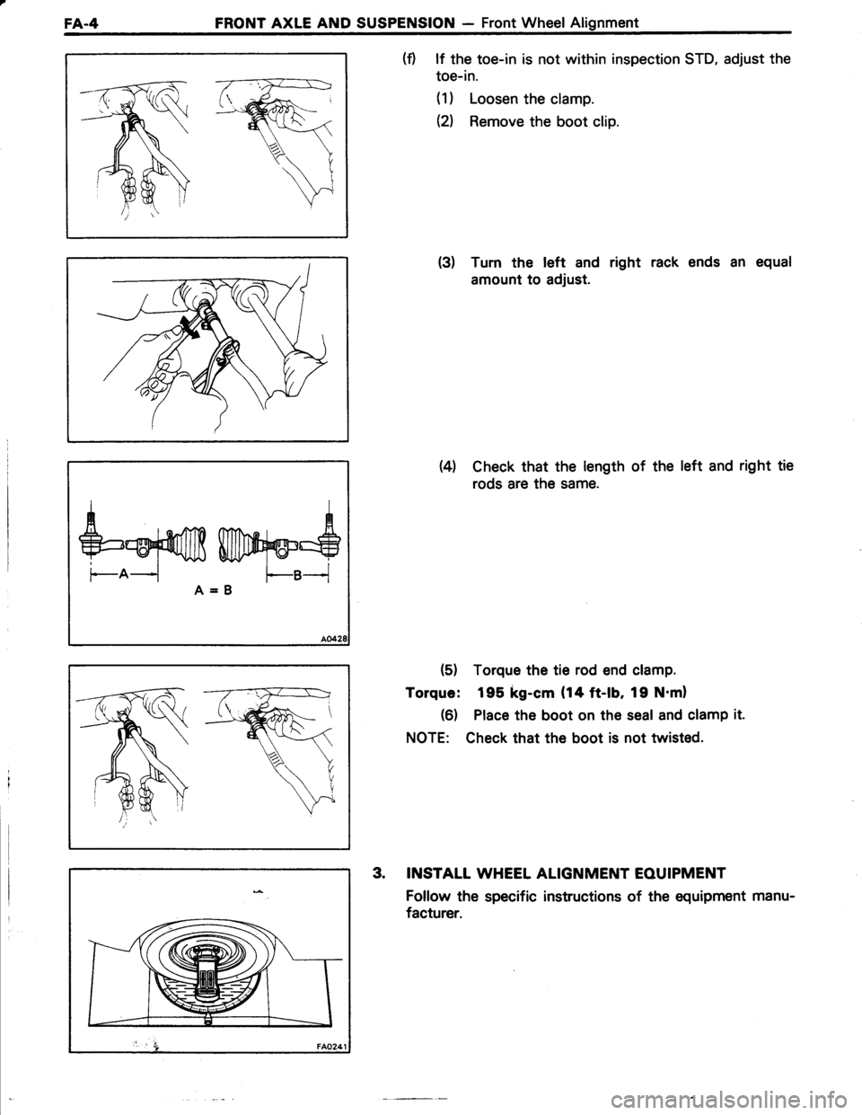
(f) lf the toe-in is not within inspection STD, adjust the
toe-in.
(1) Loosen the clamp.
el Remove the boot clip.
(3) Turn the left and right rack ends an equal
amount to adjust.
Wl Check that the length of the left and right tie
rods are the same.
(5) Torque the tie rod end clamp.
Torque: 195 kg-cm (14 ft-lb, 19 N'ml
(6) Place the boot on the seal and clamp it.
NOTE: Check that the boot is not twisted.
3. INSTALT WHEEL ALIGNMENT EOUIPMENT
Follow the specific instructions of the equipment manu-
facturer.
fuwry'$A=B
Page 491 of 885
_ l +l i'-:r': : '
FRONT AXLE AND SUSPENSION - Axle HubFA-l1
3.3 -+
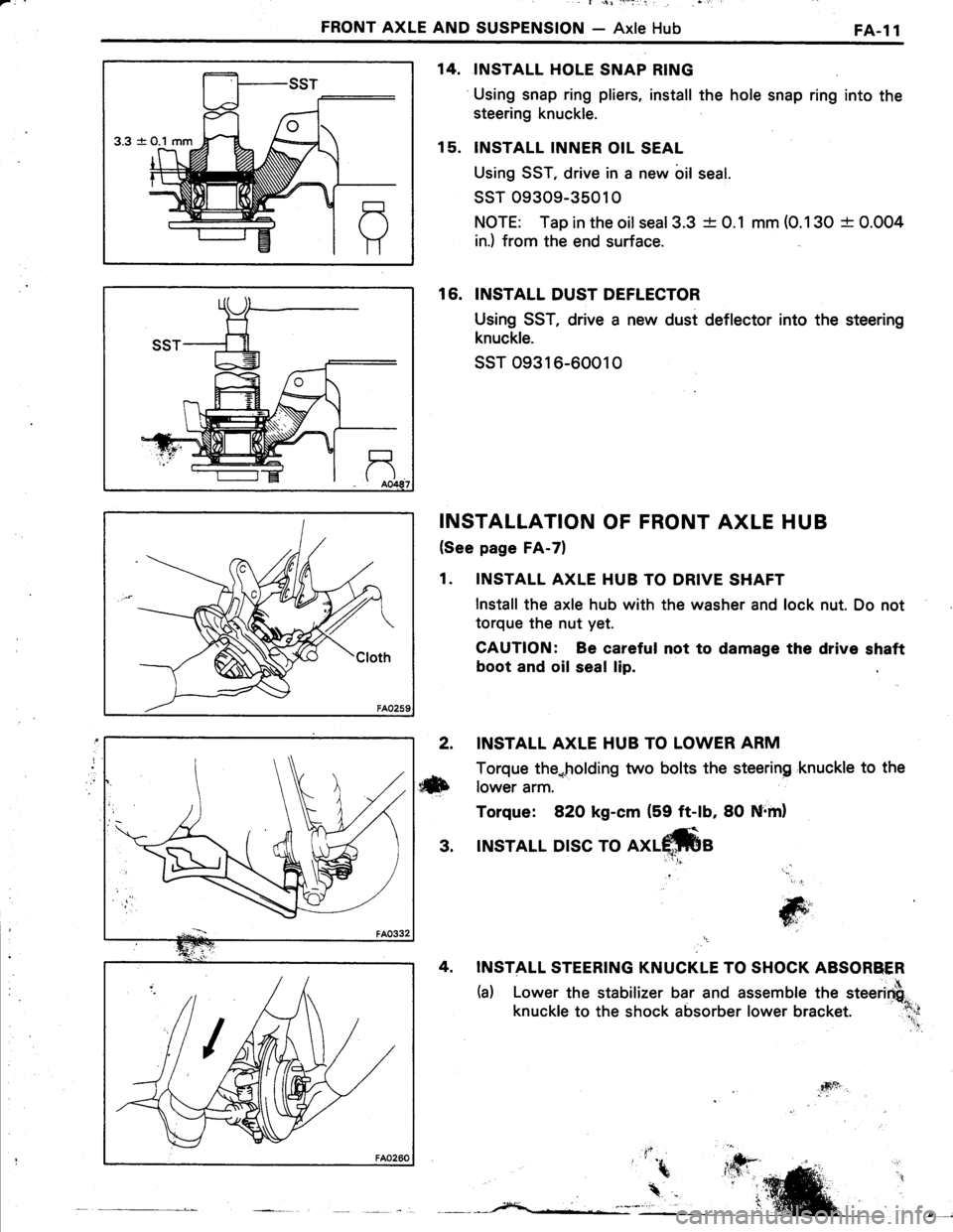
INSTALL HOLE SNAP RING
Using snap ring pliers, install the hole snap ring into the
steering knuckle.
INSTALL INNER OIL SEAL
Using SST, drive in a new bil seal.
ssT 09309-35010
NOTE: Tap in the oilseal3.3 -t- 0.1 mm (O.130 + 0.004
in.) from the end surface.
16. INSTALL DUST DEFLECTOR
Using SST, drive a new dust deflector into the steering
knuckle.
ssT o9316-60010
INSTALLATION OF FRONT AXLE HUB
(See page FA-7)
1. INSTALL AXLE HUB TO DRIVE SHAFT
lnstall the axle hub with the washer and lock nut. Do not
torque the nut yet.
CAUTION: Be careful not to damage the drive shaft
boot and oil seal lip.
14.
15.
2. INSTALL AXLE HUB TO LOWER ARM
Torque the*holding two bolts the steering 'knuckle to the
ilxb rower arm.
Torque: 82O kg-cm (59 ft-lb, 80 Nrml
3. INSTALL DISC TO
INSTALL STEERING KNUCKLE TO SHOCK ABSORBER
(a) Lower the stabilizer bar and assemble the steerirfi"
knuckle to the shock absorber lower bracket. :l;;
'' .!
jG;','
T6i'
4sft
Page 494 of 885
1FA.l4FRONT AXLE AND SUSPENSION - Front Drive Shaft
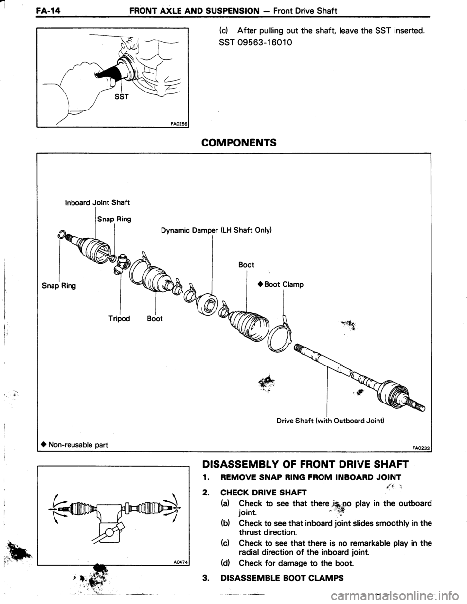
(d After pulling out the shaft, leave the SST inserted.
ssT 09563-1 601 0
DISASSEMBLY OF FRONT DRIVE SHAFT
1. REMOVE SNAP R|NG FROM TNBOARD'OITI
2. CHECK DRIVE SHAFT ,-
(a) Check to see that there jS.po play in the outboard
joint. ' :*
(b) Check to see that inboard joint slides smoothly in the
thrust direction.
(c) Check to see that there is no remarkable play in the
radial direction of the inboard joint.
(d Check for damage to the boot.
3. DISASSEMBLE BOOT CLAMPS
COMPONENTS
Dynamic Damper (LH Shaft Only)
L*lt,.tf.
{ft
Drive Shaft (with Outboard Joint)
O Non-reusable part
Inboard Joint Shaft
Tripod
Boot
,,h
Page 495 of 885
FRONT AXLE AND SUSPENSION - Front Drive ShaftFA-l5
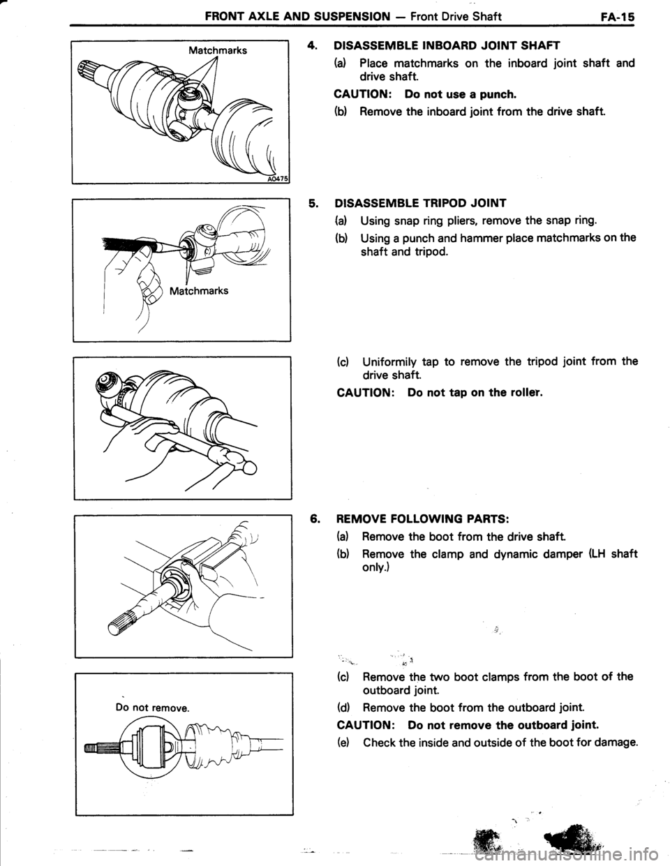
4. DISASSEMBLE INBOARD JOINT SHAFT
(d Place matchmarks on the inboard joint shaft and
drive shaft.
CAUTION: Do not use a punch.
(b) Remove the inboard joint from the drive shaft.
5. DISASSEMBLE TRIPOD JOINT
{a) Using snap ring pliers, remove the snap ring.
(d Using a punch and hammer place matchmarks on the
shaft and tripod.
(d Uniformily tap to remove the tripod joint from the
drive shaft.
CAUTION: Do not tap on the roller.
6. REMOVE FOLLOWING PARTS:
(a) Remove the boot from the drive shaft
(b) Remove the clamp and dynamic damper (LH shaft
only.)
i,l_
nrn
(c) Remove the two boot clamps from the boot of the
outboard joint.
(d) Remove the boot from the outboard joint.
CAUTION: Do not remove the outboard joint.
(e) Check the inside and outside of the boot for damage.
Do not remove.
-ffi,,.@,
Page 496 of 885
FA-l6FRONT AXLE AND SUSPENSION - Front Drive Shaft
TVinylTape
406 mm r(15.98 in.) |
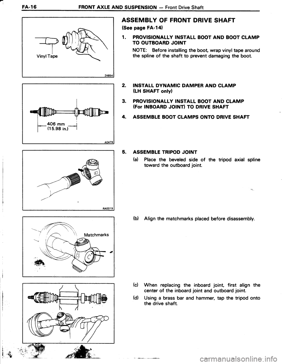
ASSEMBLY OF FRONT DRIVE SHAFT
(See page FA-l41
1. PROVISIONALLY INSTALL BOOT AND BOOT CLAMP
TO OUTBOARD JOINT
NOTE: Before installing the boot wrap vinyltape around
the spline of the shaft to prevent damaging the boot.
INSTALL DYNAMIC DAMPER AND CLAMP
(LH SHAFT onlyl
PROVISIONALLY INSTALL BOOT AND CLAMP(For INBOARD JOINTI TO DRIVE SHAFT
ASSEMBLE BOOT CLAMPS ONTO DRIVE SHAFT
ASSEMBLE TRIPOD JOINT
(a) Place the beveled side of the tripod axial spline
toward the outboard joint.
(b) Align the matchmarks placed before disassembly.
When replacing the inboard joint, first align the
center of the inboard joint and outboard joint.
Using a brass bar and hammer, tap the tripod onto
the drive shaft.
2.
3.
4.
5.
(c)
i
I.{
-^'re
t,-/
(d)
Page 497 of 885
FRONT AXLE AND SUSPENSION - Front Drive ShaftFA-l7
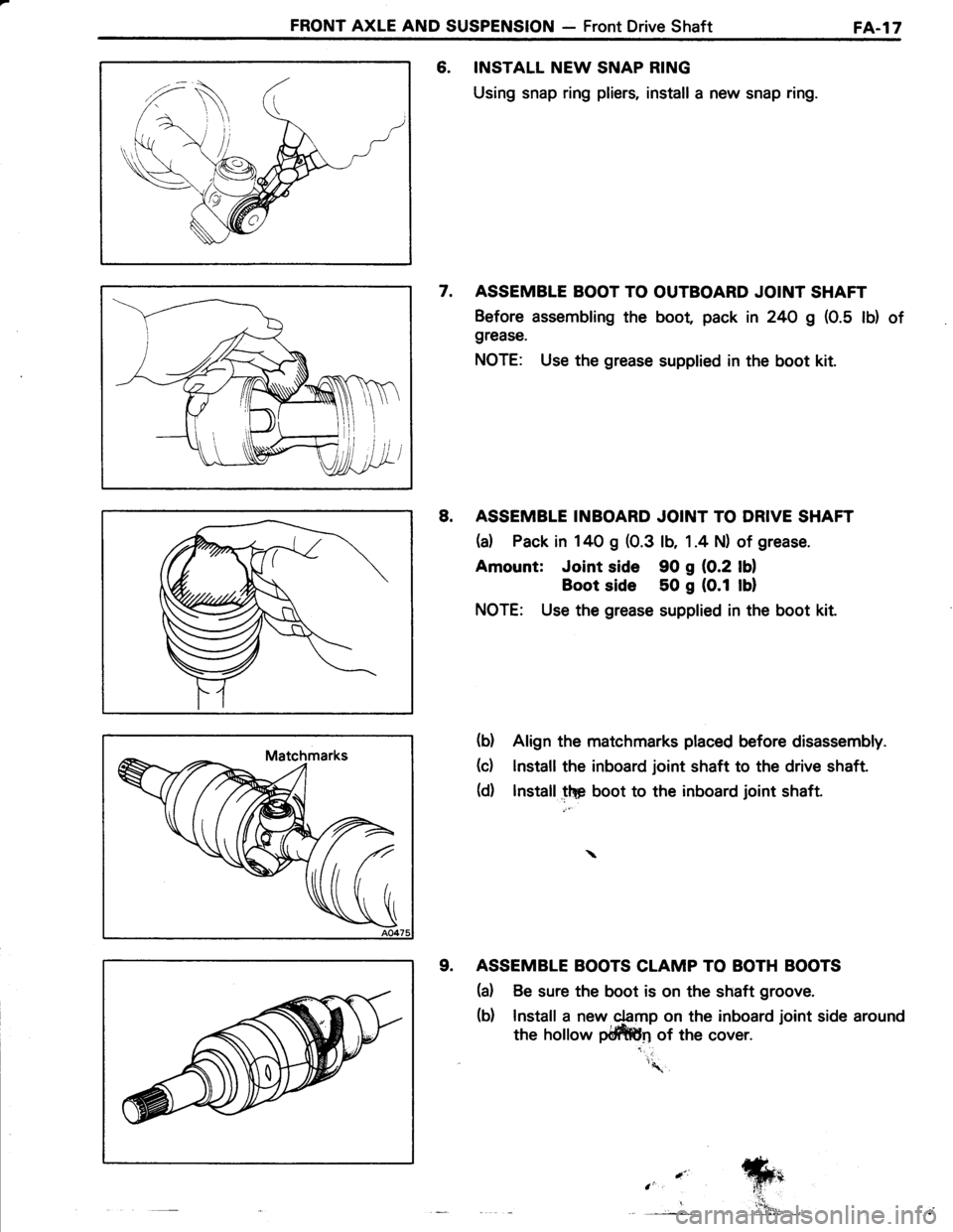
6. INSTALL NEW SNAP RING
Using snap ring pliers, install a new snap ring.
7. ASSEMBLE BOOT TO OUTBOARD JOINT SHAFT
Before assembling the boot pack in 24O g (0.5 lb) of
grease.
NOTE: Use the grease supplied in the boot kit.
8. ASSEMBLE INBOARD JOINT TO DRIVE SHAFT
(a) Pack in 140 g (0.3 lb, 1 .4 N) of grease.
Amount: Joint side 90 g {0.2 lOl
Boot side 50 g (0.1 lul
NOTE: Use the grease supplied in the boot kit.
(b) Align the matchmarks placed before disassembly.
(c) lnstall the inboard joint shaft to the drive shaft.
(d) lnstall.lF Uoo, to the inboard joint shaft.
9. ASSEMBLE BOOTS CLAMP TO BOTH BOOTS
(d Be sure the boot is on the shaft groove.
(b) Install a new 4amp on the inboard joint side around
the hollow pffin of the cover.
'\.
.-"
e_
Page 498 of 885
I
FA-l8FRONT AXLE AND SUSPENSION - Front Drive Shaft
Length
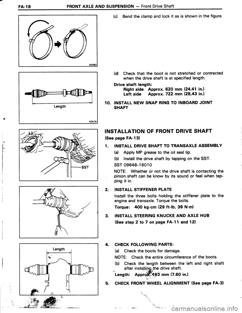
(c) Bend the clamp and lock it as is shown in the figure.
(d) Check that the boot is not stretched or contracted
when the drive shaft is at specified length.
Drive shaft length:
Right side Approx. 620 mm 124.41 in.l
Left side Approx. 722 mm (28,43 in.)
10. INSTALL NEW SNAP RING TO INBOARD JOINT
SHAFT
INSTALLATION OF FRONT DRIVE SHAFT
(See page FA-l3)
1. INSTALL DRIVE SHAFT TO TRANSAXLE ASSEMBLY
(a) Apply MP grease to the oil seal lip.
(b) lnstall the drive shaft by tapping on the SST.
ssT 09648-16010
NOTE: Whether or not the drive shaft is contacting the
pinion shaft can be know by its sound or feel when tap-
ping it in.
INSTALL STIFFENER PLATE
lnstall the three bolts holding the stiffener plate to the
engine and transaxle. Torque the bolts.
Torque: 400 kg-cm (29 ft-lb, 39 N'm)
INSTALL STEERING KNUCKE AND AXLE HUB
(See step 2 to 7 on page FA-l1 and 12)
4. CHECK FOLLOWING PARTS:
(d Check the boots for damage.
NOTE: Check the entire circumference of the boots.
(b) Check the length between the left and right shaft
after installinq,.the drive shaft.i": ' -|*itLength: Approjff{93 mm (7.60 in.)
5. CHECK FRONT"WHEEL ALIGNMENT (See page FA-31
2.
3.
"1.
Page 500 of 885
FA-20FRONT AXLE AND SUSPENSION - Front Shock Absorber
w/o PS
w/ PS and 4WD
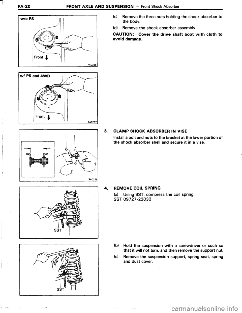
(c) Remove the three nuts holding the shock absorber to
the body.
(d Remove the shock absorber assembly.
CAUTION: Cover the drive shaft boot with cloth to
avoid damage.
3. CLAMP SHOCK ABSORBER IN VISE
Install a bolt and nuts to the bracket at the lower portion of
the shock absorber shell and secure it in a vise.
4, REMOVE COIL SPRING
(d Using SST, compress the coil spring.
ssr 09727 -22032
(b) Hold the suspension with a screwdriver or such so
that it will not turn, and then remove the support nut.
(c) Remove the suspension support, spring seat, spring
and dust cover.
tr-;
W
Page 572 of 885
BRAKE SYSTEM - Master CylinderBR-l3
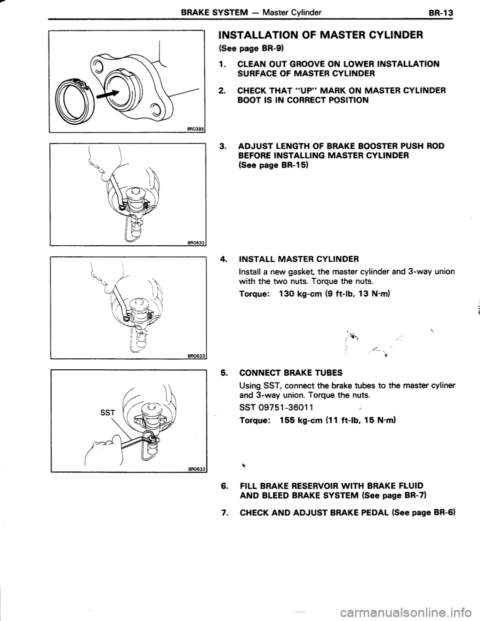
INSTALLATION OF MASTER CYLINDER
(See page BR-91
1. CLEAN OUT GROOVE ON LOWER INSTALLATION
SURFACE OF MASTER CYLINDER
2. CHECK THAT ''VP" MARK ON MASTER CYLINDER
BOOT IS IN CORRECT POSITION
3. ADJUST LENGTH OF BRAKE BOOSTER PUSH ROD
BEFORE INSTALLING MASTER CYLINDER
(See page BR-151
4. INSTALL MASTER CYLINDER
Install a new gasket, the master cylinder and 3-way union
with the two nuts. Torque the nuts.
Torque: 130 kg-cm (9 ft-lb, 13 N.ml
*
5. CONNECT BRAKE TUBES
Using SST, connect the brake tubes to the master cyliner
and 3-way union. Torque the nuts.
ssr 09751-3601 1 ;
Torque: 155 kg-cm (11ft-lb, 15 N'ml
1?
6. FILL BRAKE RESERVOIR WITH BRAKE FLUID
AND BLEED BRAKE SYSTEM {See page BR-71
7. CHECK AND ADJUST BRAKE PEDAL (See page BR-61
Page 577 of 885
BR-l8BRAKE SYSTEM - Front Brake
'- t.t
d[
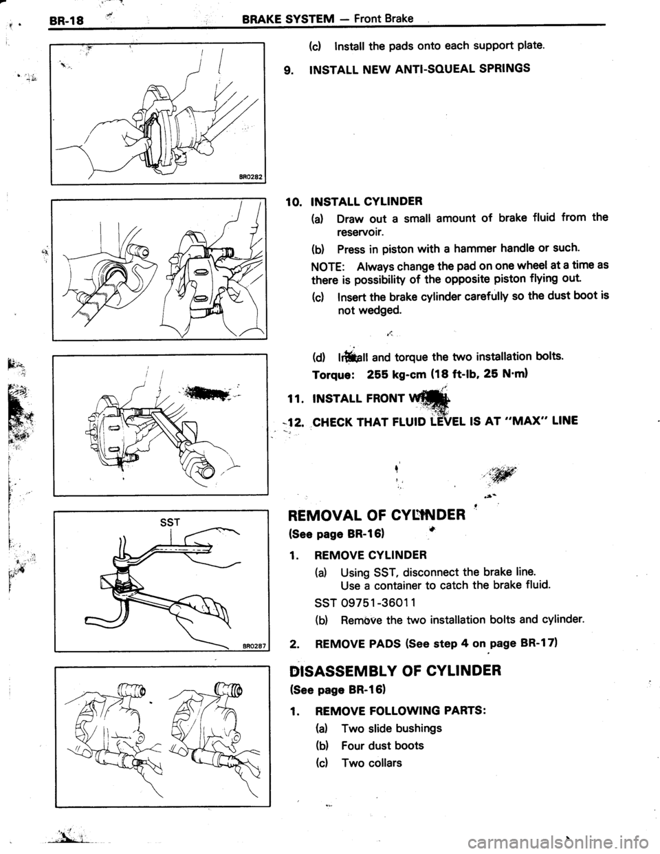
(c! Install the pads onto each support plate'
9. INSTALL NEW ANTI-SOUEAL SPRINGS
10. INSTALL CYLINDER
(d Draw out a small amount of brake fluid from the
reservoir.
(b) Press in piston with a hammer handle or such.
NOTE: Always change the pad on one wheel at a time as
there is possibility of the opposite piston flying out
(c) Insert the brake cylinder carefully so the dust boot is
not wedged.
t1.,
(d) lrfiiprr and torque the two instatlation bolts.
Torque: 255 kg-cm (18 ft-lb, 25 N'ml
t t. tNsrArL FRoNr Itr#
*12. CHECK THAT FLUID TEVEL IS AT "MAX" LINE
I,iw,i
REMOVAL OF CYUTNDER '
(See page BR-l61
1. REMOVE CYLINDER
(a) Using SST, disconnect the brake line.
Use a container to catch the brake fluid.
ssT 09751 -3601 1
(b) Rembve the two installation bolts and cylinder.
2. REMOVE PADS (See step 4 on.page BR-l71
DISASSEMBLY OF CYLINDER
(See page BR-l61
1. REMOVE FOLLOWING PARTS:
(a) Two slide bushings
(b) Four dust boots
(d Two collars
I'idr
SST
"'L i-