brake TOYOTA TERCEL 1985 Repair Manual
[x] Cancel search | Manufacturer: TOYOTA, Model Year: 1985, Model line: TERCEL, Model: TOYOTA TERCEL 1985Pages: 885, PDF Size: 64.52 MB
Page 487 of 885
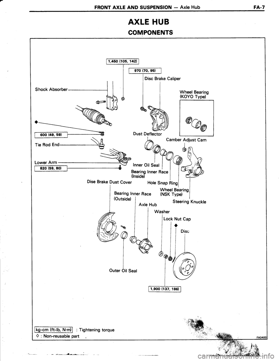
FRONT AXLE AND SUSPENSION - Axle HubFA.7
AXLE HUB
COMPONENTS
1,450 (105, 142)
Disc Brake Caliper
shocknusoruer-----'1 I I i I wheet Bearins
ntdliff*>> q$J d^%J- |
*@r
rie Rod r"o \E
h^
t.''"'lo:'t cam
:-\^'
*9@n^6g1'
i:T:":it:i Y9J'A-
ffi31?yrnnerRacel l*ryDise Brake Dust cover t"'" *1":iHJ"r,""l
Lt^:::l1l"ner Race (NSK rype) -l
a?6,
I
iOuter Oit Seal
Lock Nut Cap
ir
/1"i"
Y&r-A
lSU
Ikg-cm (ft-lb, N.m)l : Tightening torque
O : Non-reusable part
Page 488 of 885
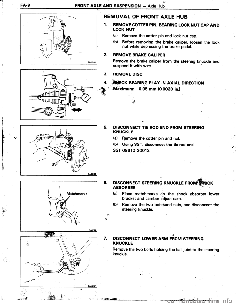
nIFA.8FRONT AXLE AND SUSPENSION- Axle Hub
REMOVAL OF FRONT AXLE HUB
1. REMOVE COTTER PIN. BEARING LOCK NUT CAP AND
LOCK NUT
(a) Remove the cotter pin and lock nut cap.
(b) Before removing the brake caliper, loosen the lock
nut while depressing the brake pedal.
2. REMOVE BRAKE CALIPER
Remove the brake caliper from the steering knuckle and
suspend it with wire.
REMOVE DISC
*fi*frcr BEARTNG pLAy rN AxtAL DtREcnoN
'' Maximum: 0.05 mm (O.OO2O in.l
5. DISCONNECT TIE ROD END FROM STEERING
KNUCKLE
(d Remove the cotter pin and nut.
(b) Using SST, disconnect the tie rod end.
ssT 09610-20012
(Le rnorrn*fucr6. DISCONNECT STEERING KNUCI
nC
t
rY
I
ItI
Ili
,
)t-5f'
ABSORBER
(d Place matchmarks on the shock absorber lower
bracket and camber adjust cam.
(b) Remove the two boltsend nuts, and disconnect the
steering knuckle.
DISCONNECT LOWER ARM FiOM STEERING
KNUCKLE
Remove the two bolts holding the balljoint to the steering
knuckle.
7.
.. ...t
3.
4.
".-*ffi,i.,.*f.isEl;-*r: .
Page 489 of 885
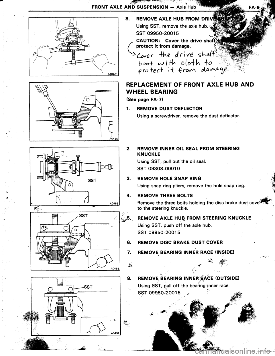
FRONT AXLE AND SUSPENSION - Axle Hub
8. REMOVE AXLE HUB FROM
Using SST, remove the axle hub.
ssT 09950-2001 5
,. CAUTION: Cover the drive shaftrhl
( protect it from damage. (r':q
;; , +in f,rlve tl""ff\ii
!,ocr* d i t{" cIo*h to " .rr:'r,
g ra *e c* i t € ro*r ata ^4 1e.
REPLACEMENT OF FRONT AXLE HUB AND
WHEEL BEARING
(See page FA-7)
1. REMOVE DUST DEFLECTOR
Using a screwdriver, remove the dust deflector.
REMOVE INNER OIL SEAL FROM STEERING
KNUCKLE
Using SST, pull ou.t the oil seal.
ssr 09308-0001 0
REMOVE HOLE SNAP RING
Using snap ring pliers, remove the hole snap ring.
REMOVE THREE BOLTS
Remove the three bolts holding the disc brake dust
to the steering knuckle.
,..F. REMOVE AXLE HUQ FROM STEERING KNUCKLE€r:
Using SST, push off the axle hub.
ssT 09950-2001 5
6. REMOVE DISC BRAKE DUST COVER
7. REMOVE BEARING INNER RACE'(INSIDE)
2.
a
,{n.1n
t
3.
4.
fr
,f+
8. REMOVE. BEARTNG rlruen.qAbe (OUrSlOe)
Using 9ST, pull off the beaiing'inner race.
ssT 09950;20015 t r
Page 490 of 885
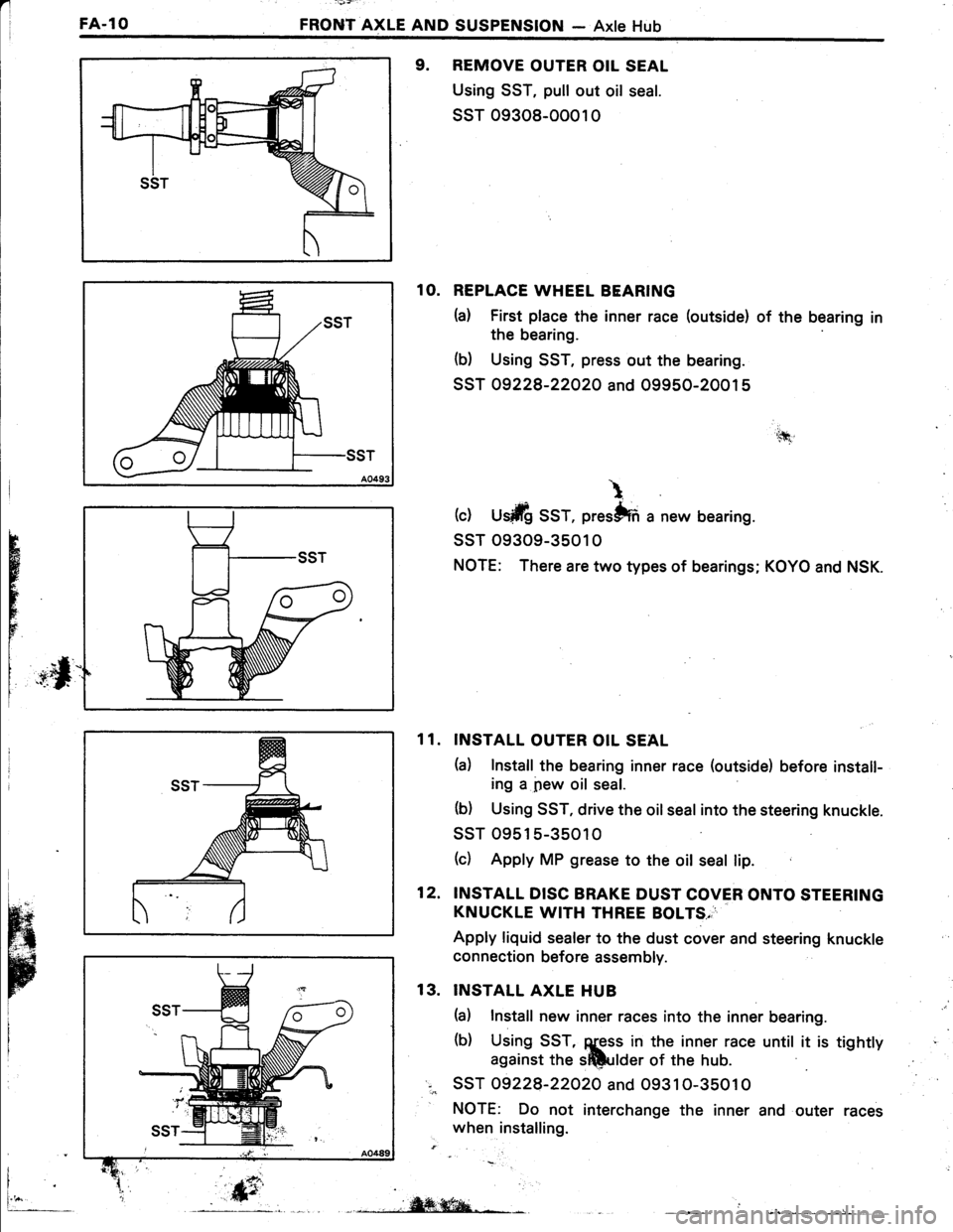
FA.1O
' -'v7:'
FRONT AXLE AND SUSPENSION - Axle Hub
9. REMOVE OUTER OIL SEAL
Using SST, pull out oil seal.
ssT 09308-0001 0
1O. REPLACE WHEEL BEARING
h) First place the inner race (outside) of the bearing in
the bearing
(b) Using SST, press out the bearing.
SST 09228-22O2O and 09950-20015
(c) U$ilfi SST, prestffi a new bearing.
ssT 09309-3501 0
NOTE: There are two types of bearings; KOYO and NSK.
INSTALL OUTER OIL SEAL
h) Install the bearing inner race (outside) before install-
ing a pew oil seal.
(b) Using SST, drive the oil seal into the steering knuckle.
ssT 09515-35010
(c) Apply MP grease to the oit seal lip.
INSTALL DISC BRAKE DUST COVER ONTO STEERING
KNUCKLE WITH THREE BOLTS,
Apply liquid sealer to the dust cover and steering knuckle
connection before assembly.
INSTALL AXLE HUB
(a) Install new inner races into the inner bearing.
(b) Using SST, ggss in the inner race until it is tightty
against the sftlulder of the hub.
SST 09228-22O2O and O9310-35010
NOTE: Do not interchange the inner and outer races
when installing.
'.tfi
\
H
r
FE
11.
12.
13.
i
fr_, .,,iW;ffiqa-*L- L __
Page 492 of 885
'l
FA..12FRONT AXLE AND SUSPENSION - Axle Hub
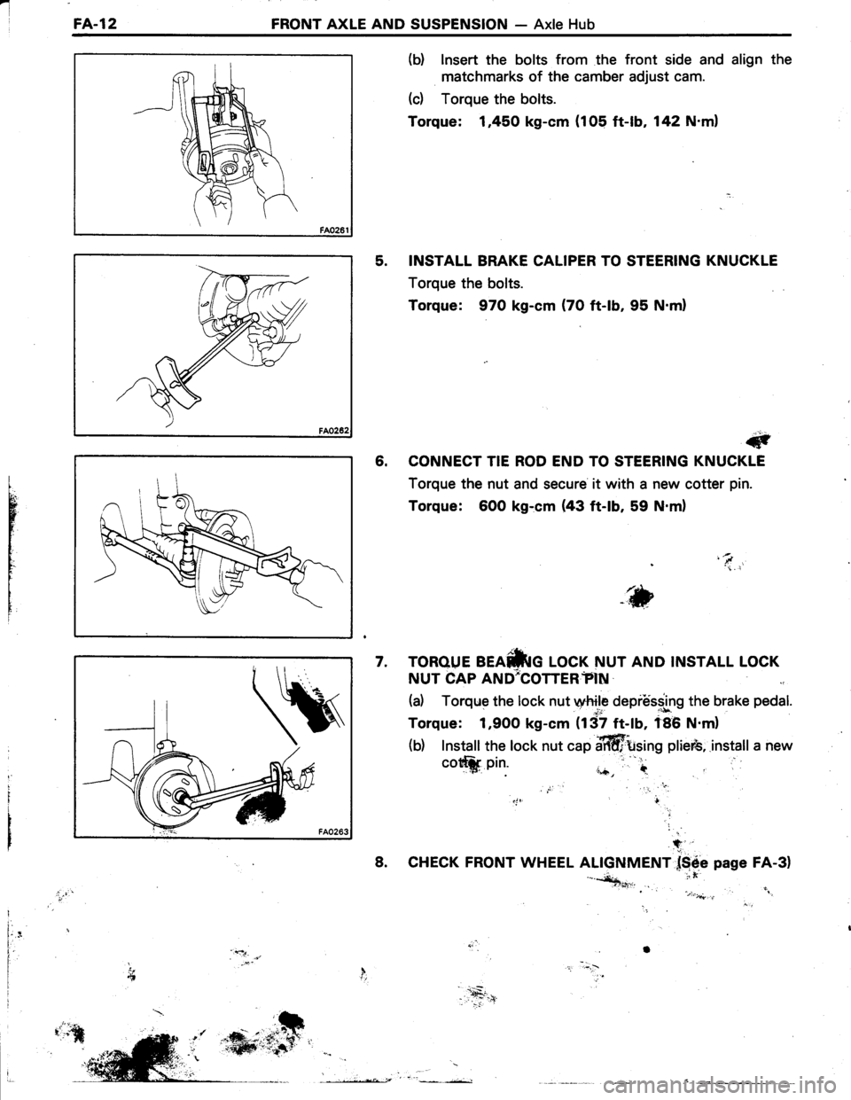
(b) lnsert the bolts from the front side and align the
matchmarks of the camber adjust cam.
(c) Torque the bolts.
Torque: 1,450 kg-cm (105 ft-lb, 142 N'ml
5. INSTALL BRAKE CALIPER TO STEERING KNUCKLE
Torque the bolts.
Torque: 970 kg-cm (70 ft-lb, 95 N.ml
#
6. CONNECT TIE ROD END TO STEERING KNUCKLE
Torque the nut and secure it with a new cotter pin.
Torque: 6O0 kg:cm (43 ft-lb, 59 N.m)
'\i. i
tr,bWVii
i
TOROUE BEAfriG LOCK NUT AND INSTALL LOCK
NUT CAP AND;COTTER?IN
(a) Torqrle the lock nut wtrile depiUs.s.lng the brake pedal.
Torque: 1,900 kg-cm (137 ft-lb, f86 N.m)
(b) Install the lock nut cap affittsing plieib,.install a new
7.
cott*. pin.
8.
+
CHECK FRONT WHEEL ALIGNMENT f$6e page FA-3)'-*+***n,. it'., . .i .:)".4..,,'i".: "
Il.I
f,'l.
Page 493 of 885
![TOYOTA TERCEL 1985 Repair Manual FRONT AXLE AND SUSPENSION - Front Drive ShaftFA.13
FRONT DRIVE SHAFT
REMOVAL OF FRONT DRIVE SHAFT
Shock Absorber
Stiffener Plate(Left Side Only)
ffi-:
\R---\x+.
Tie Rod End---€
lRgrcm ITi-|b,T.mi] : TOYOTA TERCEL 1985 Repair Manual FRONT AXLE AND SUSPENSION - Front Drive ShaftFA.13
FRONT DRIVE SHAFT
REMOVAL OF FRONT DRIVE SHAFT
Shock Absorber
Stiffener Plate(Left Side Only)
ffi-:
\R---\x+.
Tie Rod End---€
lRgrcm ITi-|b,T.mi] :](/img/14/57472/w960_57472-492.png)
FRONT AXLE AND SUSPENSION - Front Drive ShaftFA.13
FRONT DRIVE SHAFT
REMOVAL OF FRONT DRIVE SHAFT
Shock Absorber
Stiffener Plate(Left Side Only)
ffi-:
\R---\x+.
Tie Rod End---€
lRgrcm ITi-|b,T.mi] : Tishtening torque
O : Non-reusable part
Disc Brake Caliper
1.900 {137, 186}Lower Arm
.t.
1. REMOVE STEERING KNUCKE AND
AXLE HUB WITHOUT DISCONNECTING
LOWER ARM
(See step 1 to 6 and 8 on page FA-81
2. REMOVE FRONT DRIVE SHAFT
(a) Remove the stiffener plate from the transaxle as-
sembly and"engine (left side only).
(b) Using SST.and a hammer, tap out the front drive
shaft.
ssr 09648-16010
k
Page 513 of 885
REAR AXLE AND SUSPENSION - Rear Axle Hub and Carrier (FWD) RA-s
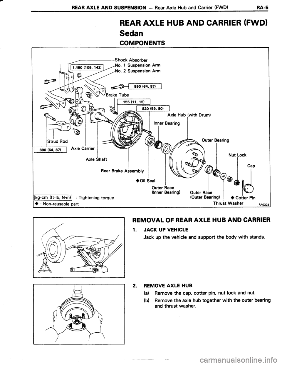
REAR AXLE HUB AND CARRIER (FWDI
Sedan
COMPONENTS
REMOVAL OF REAR AXLE HUB AND CARRIER
1. JACK UP VEHICLE
Jack up the vehicle and support the body with stands.
2. REMOVE AXLE HUB
(a) Remove the cap, cotter pin, nut lock and nut.
(b) Remove the axle hub together with the outer bearing
and thrust washer.
No. 1 Suspension Arm
No. 2 Suspension Arm
Brake Tube
Axle Hub (with Drum)
\,outer
Bearins
a | *u..o"*
W^I | ',,
Y
Y*q@l l
outernale t
*ld
(Outer Bearing) | a Coiter Pin
Thruit Washer
Outer Race(lnner Bearing)
lkg-cm (ft-lb. N.m)l : Tightening torque
O : Non-reusable part
Page 514 of 885
-
RA-6 REAR AXLE AND SUSPENSION - Rear Axle Hub and Carrier (FWD)
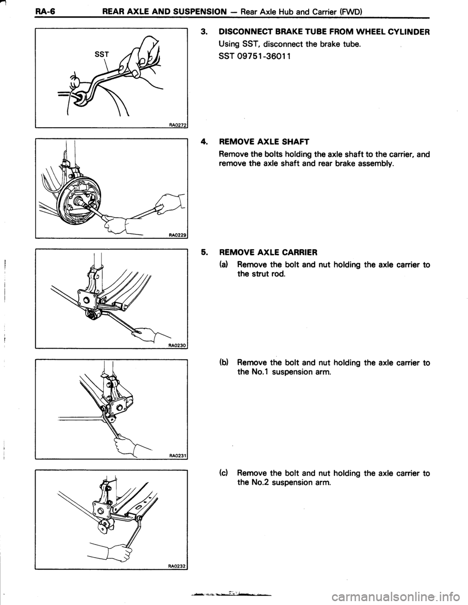
3. DISCONNECT BRAKE TUBE FROM WHEEL CYLINDER
Using SST, disconnect the brake tube.
ssT 09751 -3601 1
4. REMOVE AXLE SHAFT
Remove the bolts holding the axle shaft to the carrier, and
remove the axle shaft and rear brake assembly.
5. REMOVE AXLE CARRIER
(d Remove the bolt and nut holding the axle carrier to
the strut rod.
(b) Remove the bolt and nut holding the axle carrier to
the No.1 suspension arm.
(d Remove the bolt and nut holding the axle carrier to
the No.2 suspension arm.
Page 517 of 885
REAR AXLE AND SUSPENSION - Rear Axle Hub and Carrier (FWD) RA-g
RA0238
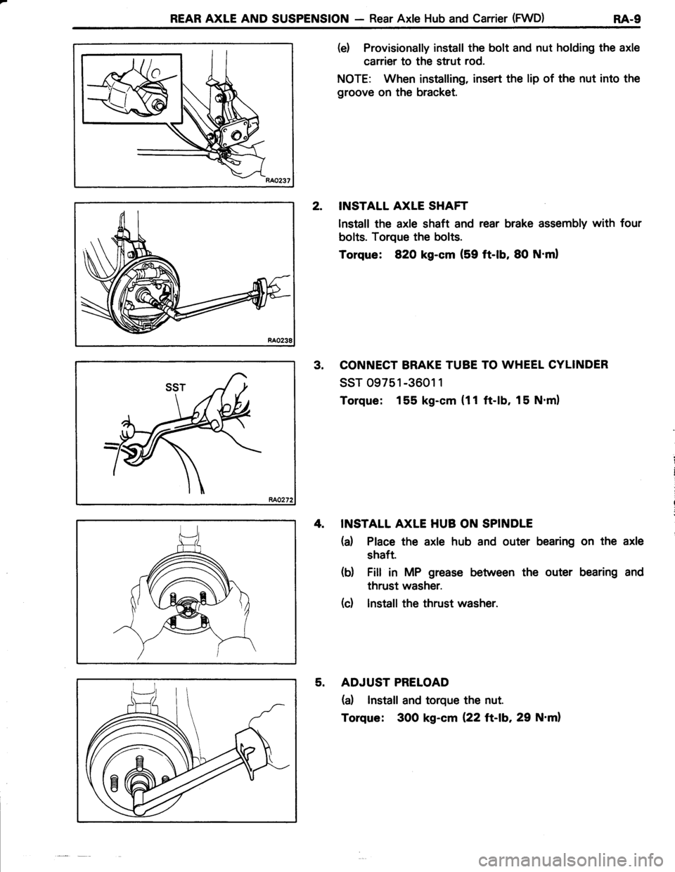
(e) Provisionally install the bolt and nut holding the axle
carrier to the strut rod.
NOTE: When installing, insert the lip of the nut into the
groove on the bracket.
2. INSTALL AXLE SHAFT
lnstall the axle shaft and rear brake assembly with four
bolts. Torque the bolts.
Torque: 820 kg-cm (59 ft-lb, 80 N'ml
3. CONNECT BRAKE TUBE TO WHEEL CYLINDER
ssr 09751 -3601 1
Torque: 155 kg-cm (11 ft-lb. 15 N.m)
4. INSTALL AXLE HUB ON SPINDLE
(a) Place the axle hub and outer bearing on the axle
shaft.
(b) Fill in MP grease between the outer bearing and
thrust washer.
(d lnstall the thrust washer.
5. ADJUST PRELOAD
(a) Install and torque the nut.
Torque: 300 kg-cm {22 tt-\b,29 N'ml
Page 518 of 885
r.1
E4-10 REAR AXLE AND SUSPENSION - Rear Axle Hub and Canier (FWD)
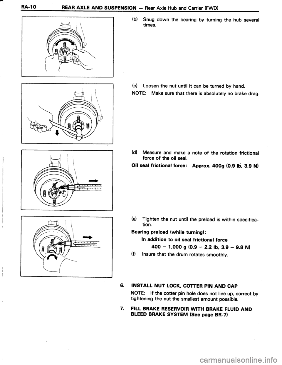
(b) Snug down the bearing by turning the hub several
times.
(c) Loosen the nut until it can be turned by hand.
NOTE: Make sure that there is absolutely no brake drag.
(d) Measure and make a note of the rotation frictional
force of the oil seal.
Oil sealfrictionalforce: Approx. rtoog (0.9 lb, 3.9 Nl
(e) Tighten the nut until the preload is within specifica-
tion.
Bearing preload (while turning):
In addition to oil seal frictional force
400 - 1,000 g (0.9 - 2.2 tb,3.9 - 9.8 Nl
(fl Insure that the drum rotates smoothly.
6. INSTALL NUT LOCK, COTTER PIN AND CAP
NOTE: lf the cotter pin hole does not line up, correct by
tightening the nut the smallest amount possible.
7. FILL BRAKE RESERVOIR WITH BRAKE FLUID AND
BLEED BRAKE SYSTEM (See page BR-ZI