brake light TOYOTA TERCEL 1985 Repair Manual
[x] Cancel search | Manufacturer: TOYOTA, Model Year: 1985, Model line: TERCEL, Model: TOYOTA TERCEL 1985Pages: 885, PDF Size: 64.52 MB
Page 565 of 885

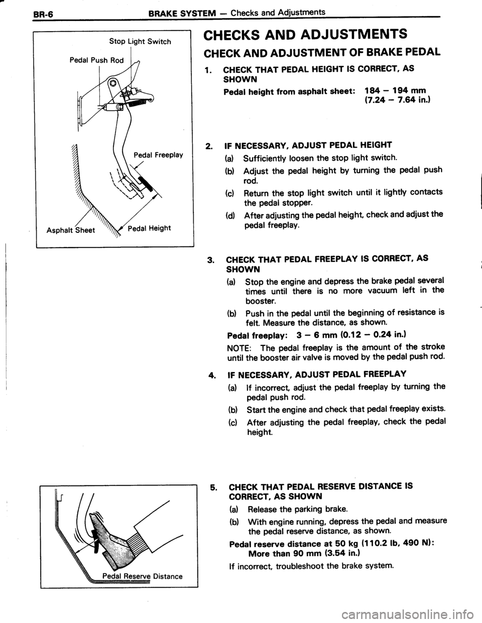
Stop Light Switch
Pedal Push Rod
Pedal Freeplay
Asphalt SheetPedat Height
BRAKE SYSTEM - Checks and
CHECKS AND ADJUSTMENTS
CHECK AND ADJUSTMENT OF BRAKE PEDAL
1. CHECK THAT PEDAL HEIGHT IS CORRECT' AS
SHOWN
Pedat heisht from asphalt slreet:
i#;:?ifil.,
IF NECESSARY. ADJUST PEDAL HEIGHT
(a) Sufficiently loosen the stop light switch.
(b) Adjust the pedal height by turning the pedal push
rod.
(c) Return the stop light switch until it lightly contacts
the pedal stopper.
(d) After adjusting the pedal height, check and adiust the
pedal freePlay.
CHECK THAT PEDAL FREEPLAY IS CORRECT, AS
SHOWN
(a) Stop the engine and depress the brake pedal several
times until there is no more vacuum left in the
booster.
(b) Push in the pedal until the beginning of resistance is
felt. Measure the distance, as shown'
Pedaf freepfay: 3 - 6 mm (0.12 - O,24 in.l
NOTE: The pedal freeplay is the amount of the stroke
until the booster air valve is moved by the pedal push rod.
IF NECESSARY, ADJUST PEDAL FREEPLAY
(a) lf incorrect adiust the pedal freeplay by turning the
pedal Push rod.
(b) Start the engine and check that pedal freeplay exists.
(c) After adjusting the pedal freeplay, check the pedal
height.
CHECK THAT PEDAL RESERVE DISTANCE IS
CORRECT, AS SHOWN
(a) Release the parking brake.
(b) With engine running, depress the pedal and measure
the pedal reserve distance, as shown.
Pedaf reserve distance at 50 kg (1 1 O-2 1b,490 Nl:
More than 90 mm (3.54 in.l
lf incorrect, troubleshoot the brake system.
Page 566 of 885

BRAKE SYSTEM - Checks and AdjustmentsBR-7
@@
VV
1 st 2nd
OPERATIONAL TEST OF BRAKE BOOSTER
NOTE: lf available, use a brake booster tester to check
the booster operating condition.
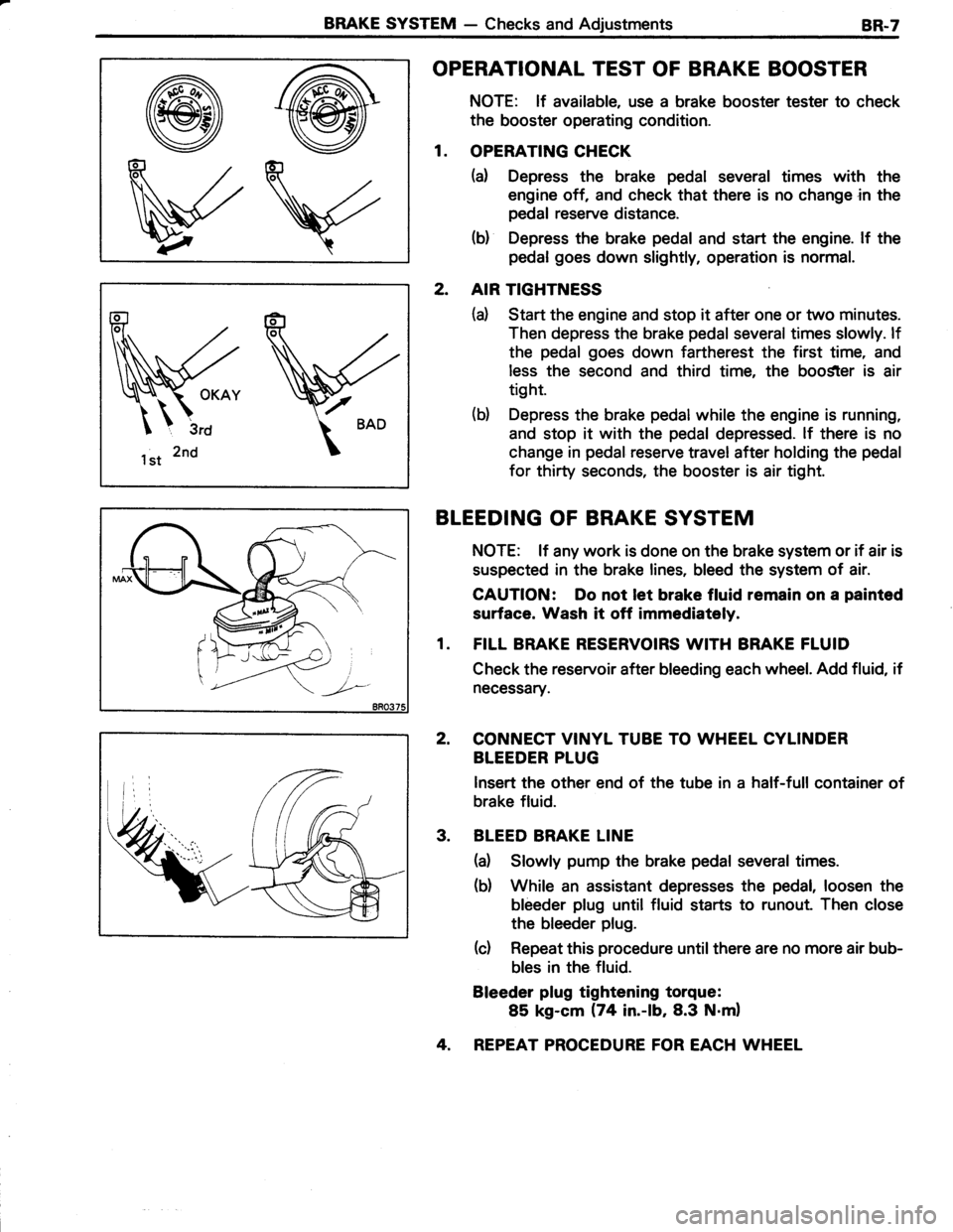
1. OPERATING CHECK
(a) Depress the brake pedal several times with the
engine off, and check that there is no change in the
pedal reserve distance.
(b) Depress the brake pedal and start the engine. lf the
pedal goes down slightly, operation is normal.
2. AIR TIGHTNESS
(d Start the engine and stop it after one or two minutes.
Then depress the brake pedal several times slowly. lf
the pedal goes down fartherest the first time, and
less the second and third time, the boo$ter is air
tight.
(b) Depress the brake pedal while the engine is running,
and stop it with the pedal depressed. lf there is no
change in pedal reserve travel after holding the pedal
for thirty seconds, the booster is air tight.
BLEEDING OF BRAKE SYSTEM
NOTE: lf any work is done on the brake system or if air is
suspected in the brake lines, bleed the system of air.
CAUTION: Do not let brake fluid remain on a painted
surface. Wash it off immediataly.
1. FILL BRAKE RESERVOIRS WITH BRAKE FLUID
Check the reservoir after bleeding each wheel. Add fluid, if
necessary.
2, CONNECT VINYL TUBE TO WHEEL CYLINDER
BLEEDER PLUG
lnsert the other end of the tube in a half-full container of
brake fluid.
3. BLEED BRAKE LINE
(a) Slowly pump the brake pedal several times.
(b) While an assistant depresses the pedal, loosen the
bleeder plug until fluid starts to runout. Then close
the bleeder plug.
(c) Repeat this procedure until there are no more air bub-
bles in the fluid.
Bleeder plug tightening torque:
85 kg-cm (74 in.-lb,8.3 N.m)
4. REPEAT PROCEDURE FOR EACH WHEEL
Page 570 of 885

BRAKE SYSTEM - Master CylinderBR-11
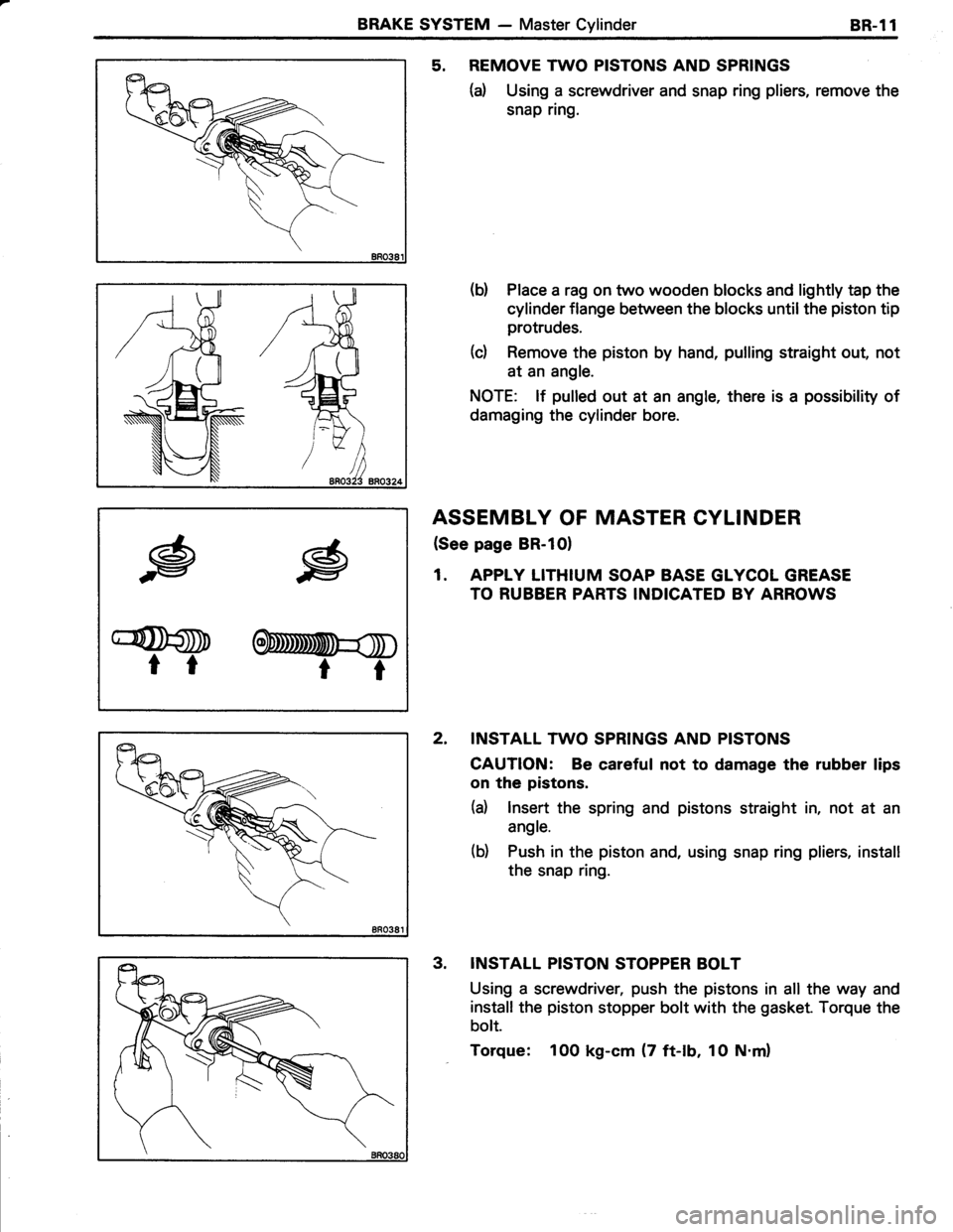
5. REMOVE TWO PISTONS AND SPRINGS
(d Using a screwdriver and snap ring pliers, remove the
snap ring.
(b) Place a rag on two wooden blocks and lightly tap the
cylinder flange between the blocks until the piston tip
protrudes.
(c) Remove the piston by hand, pulling straight out, not
at an angle.
NOTE: lf pulled out at an angle, there is a possibility of
damaging the cylinder bore.
ASSEMBLY OF MASTER CYLINDER
(See page BR-10)
1. APPLY LITHIUM SOAP BASE GLYCOL GREASE
TO RUBBER PARTS INDICATED BY ARROWS
2. INSTALL TWO SPRINGS AND PISTONS
CAUTION: Be careful not to damage the rubber lips
on the pistons.
(d lnsert the spring and pistons straight in, not at an
angle.
(b) Push in the piston and, using snap ring pliers, install
the snap ring.
INSTALL PISTON STOPPER BOLT
Using a screwdriver, push the pistons in all the way and
install the piston stopper bolt with the gasket. Torque the
bolt.
Torque: 100 kg-cm (7 ft-lb, 1O N.m)
.g
G@D
tr
.g
OnmmU=$
rt
3.
Page 574 of 885

BRAKE SYSTEM - Brake Booster8R.15
INSTALLATION OF BRAKE BOOSTER
(See page BR-l41
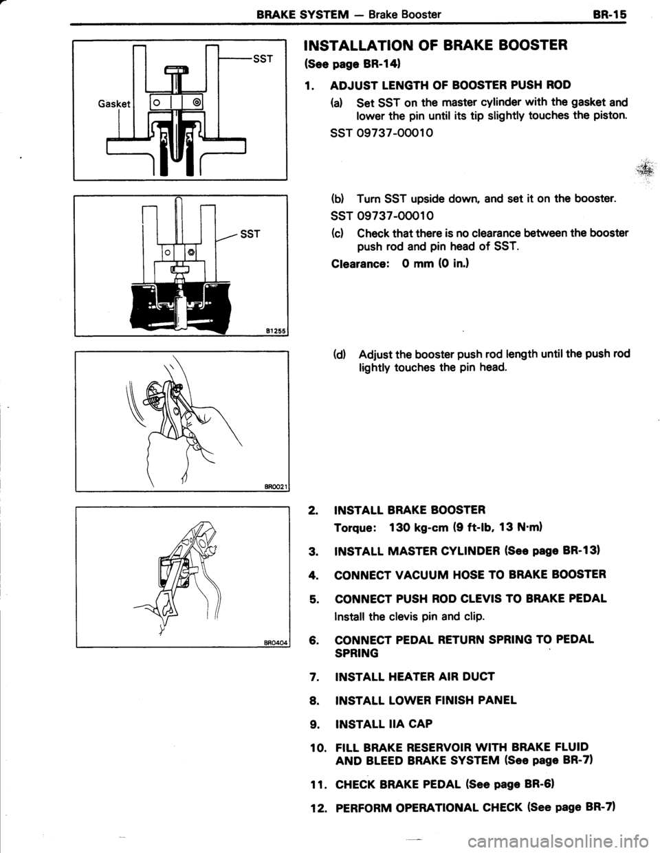
1. ADJUST LENGTH OF BOOSTER PUSH ROD
(a) Set SST on the master cylinder with the gasket and
lower the pin until its tip slightly touches the piston.
ssr 09737-00010
(d Tum SST upside down, and set it on the booster.
ssT 09737-OOO10
(c) Check that there is no clearance between the booster
push rod and pin head of SST.
Clearance: O mm (0 in.l
(d) Adjust the booster push rod length untilthe push rod
lightly touches the pin head.
2. INSTALL BRAKE BOOSTER
Torque: 130 kg-cm (9 ft-lb, 13 N'ml
3. INSTALL MASTER CYLINDER (See page BR-131
4. CONNECT VACUUM HOSE TO BRAKE BOOSTER
5. CONNECT PUSH ROD CLEVIS TO BRAKE PEDAL
Install the clevis pin and clip.
6. CONNECT PEDAL RETURN SPRING TO PEDAL
SPRING
INSTALL HEATER AIR DUCT
INSTALL LOWER FINISH PANEL
INSTALL IIA CAP
FILL BRAKE RESERVOIR WITH BRAKE FLUID
AND BLEED BRAKE SYSTEM (See page BR-71
CHECK BRAKE PEDAL (See page BR-61
PERFORM OPERATIONAL CHECK (See page BR-71
7.
8.
9.
10.
11.
12.