check oil TOYOTA TERCEL 1985 Repair Manual
[x] Cancel search | Manufacturer: TOYOTA, Model Year: 1985, Model line: TERCEL, Model: TOYOTA TERCEL 1985Pages: 885, PDF Size: 64.52 MB
Page 498 of 885
I
FA-l8FRONT AXLE AND SUSPENSION - Front Drive Shaft
Length
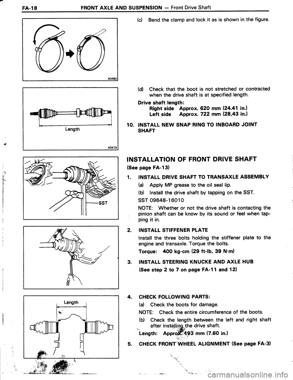
(c) Bend the clamp and lock it as is shown in the figure.
(d) Check that the boot is not stretched or contracted
when the drive shaft is at specified length.
Drive shaft length:
Right side Approx. 620 mm 124.41 in.l
Left side Approx. 722 mm (28,43 in.)
10. INSTALL NEW SNAP RING TO INBOARD JOINT
SHAFT
INSTALLATION OF FRONT DRIVE SHAFT
(See page FA-l3)
1. INSTALL DRIVE SHAFT TO TRANSAXLE ASSEMBLY
(a) Apply MP grease to the oil seal lip.
(b) lnstall the drive shaft by tapping on the SST.
ssT 09648-16010
NOTE: Whether or not the drive shaft is contacting the
pinion shaft can be know by its sound or feel when tap-
ping it in.
INSTALL STIFFENER PLATE
lnstall the three bolts holding the stiffener plate to the
engine and transaxle. Torque the bolts.
Torque: 400 kg-cm (29 ft-lb, 39 N'm)
INSTALL STEERING KNUCKE AND AXLE HUB
(See step 2 to 7 on page FA-l1 and 12)
4. CHECK FOLLOWING PARTS:
(d Check the boots for damage.
NOTE: Check the entire circumference of the boots.
(b) Check the length between the left and right shaft
after installinq,.the drive shaft.i": ' -|*itLength: Approjff{93 mm (7.60 in.)
5. CHECK FRONT"WHEEL ALIGNMENT (See page FA-31
2.
3.
"1.
Page 501 of 885
FRONT AXLE AND SUSPENSION - Front Shock AbsorberFA.21
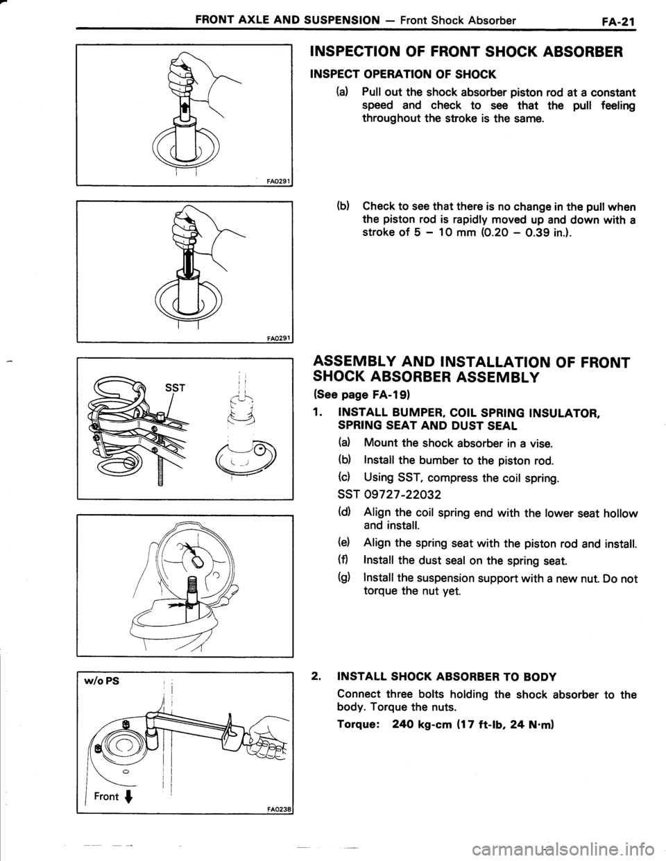
INSPECTION OF FRONT SHOCK ABSORBER
INSPECT OPERATION OF SHOCK
(d Pull out the shock absorber piston rod at a constant
speed and check to see that the pull feeling
throughout the stroke is the same.
b) Check to see that there is no change in the pull when
the piston rod is rapidly moved up and down with a
stroke of 5 - 1O mm (0.20 - 0.39 in.).
ASSEMBLY AND INSTALLATION OF FRONT
SHOCK ABSORBER ASSEMBLY
(See page FA-l91
1. INSTALL BUMPER, COIL SPRING INSULATOR,
SPRING SEAT AND DUST SEAL
(d Mount the shock absorber in a vise.
(b) lnstall the bumber to the piston rod.
(c) Using SST, compress the coil spring.
ssT 09727 -22032
(d) Align the coil spring end with the lower seat hollow
and install.
(d Align the spring seat with the piston rod and install.
(fl lnstall the dust seal on the spring seat.
(g) Install the suspension support with a new nut. Do not
torque the nut yet.
2. INSTALL SHOCK ABSORBER TO BODY
Connect three bolts holding the shock absorber to the
body. Torque the nuts.
Torque: 24O kg-cm {17 ft-lb, 24 N.ml
Page 503 of 885
FRONT AXLE AND SUSPENSION - Front SuspensionFA-23
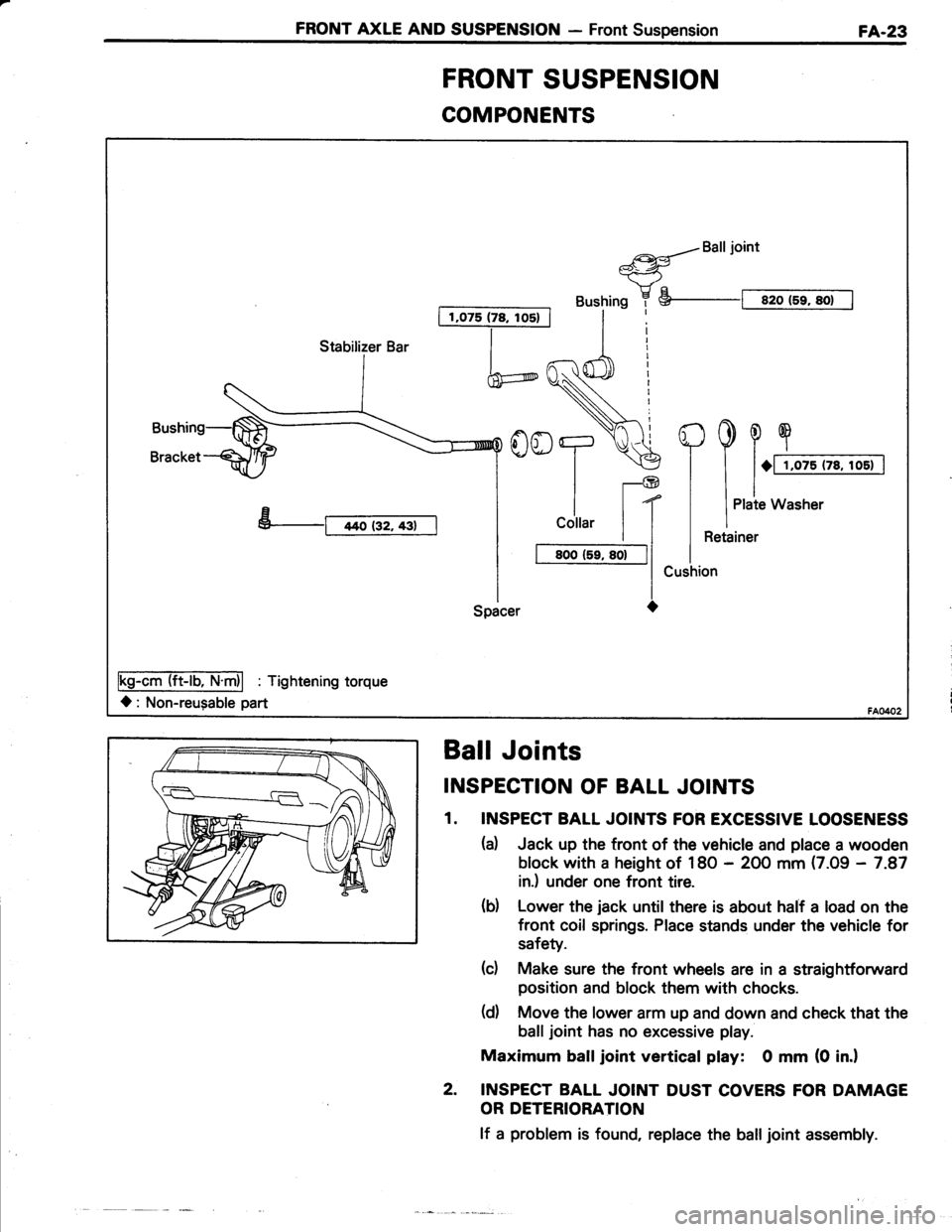
COMPONENTS
I 1,075 (78, los) |
a{Balljoint*-<-ry"
Bushing 7 S--t sro (5r, sot I
h
YooT.\€
ll-@
| | t(
I
cottar | |
I t BooCr, so-|l
l-lSpacer O
Fs-AmTliET'fri| : Tishtenins torque
l: Non-reugable part
Stabilizer Bar
FRONT SUSPENSION
Ball Joints
INSPECTION OF BALL JOINTS
1. INSPECT BALL JOINTS FOR EXCESSIVE LOOSENESS
(d Jack up the tront of the vehicle and place a wooden
block with a height of 18O - 2OO mm (7.09 - 7.87
in.) under one front tire.
(d Lower the jack until there is about half a load on the
front coil springs. Place stands under the vehicle for
safety.
(c) Make sure the front wheels are in a straightforward
position and block them with chocks.
(d) Move the lower arm up and down and check that the
balljoint has no excessive play.
Maximum balljoint vertical play: 0 mm (0 in.l
2. INSPECT BALL JOINT DUST COVERS FOR DAMAGE
OR DETERIORATION
lf a problem is found, replace the balljoint assembly.
Page 532 of 885
RA.24REAR AXLE AND SUSPENSION - Troubleshooting (4WD)
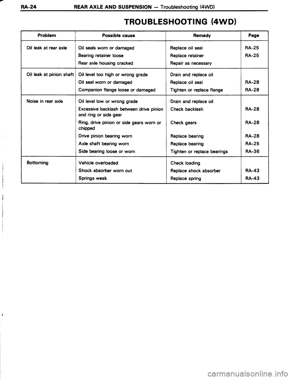
TROUBLESHOOTING (4WD}
ProblemPossible causeRemedyPage
Oil leak at rear axleOil seals worn or damaged
Bearing retainer loose
Rear axle housing cracked
Replace oil seal
Replace retainer
Repair as necessary
RA-25
RA-25
Oil leak at pinion shaftOil level too high or wrong grade
Oil sealworn or damaged
Companion flange loose or damaged
Drain and replace oil
Replace oil seal
Tighten or replace flange
RA-28
RA-28
Noise in rear axleOil level low or wrong grade
Excessive backlash between drive pinion
and ring or side gear
Ring, drive pinion or side gears worn or
chipped
Drive pinion bearing worn
Axle shaft bearing worn
Side bearing loose or worn
Drain and replace oil
Check backlash
Check gears
Replace bearing
Replace bearing
Tighten or replace bearings
RA-28
RA-28
RA-28
RA.25
RA-36
BottomingVehicle overloaded
Shock absorber worn out
Springs weak
Check loading
Replace shock absorber
Replace spring
RA.43
RA.43
Page 537 of 885
REAR AXLE AND SUSPENSION - Differential (4WD)RA.29
SST
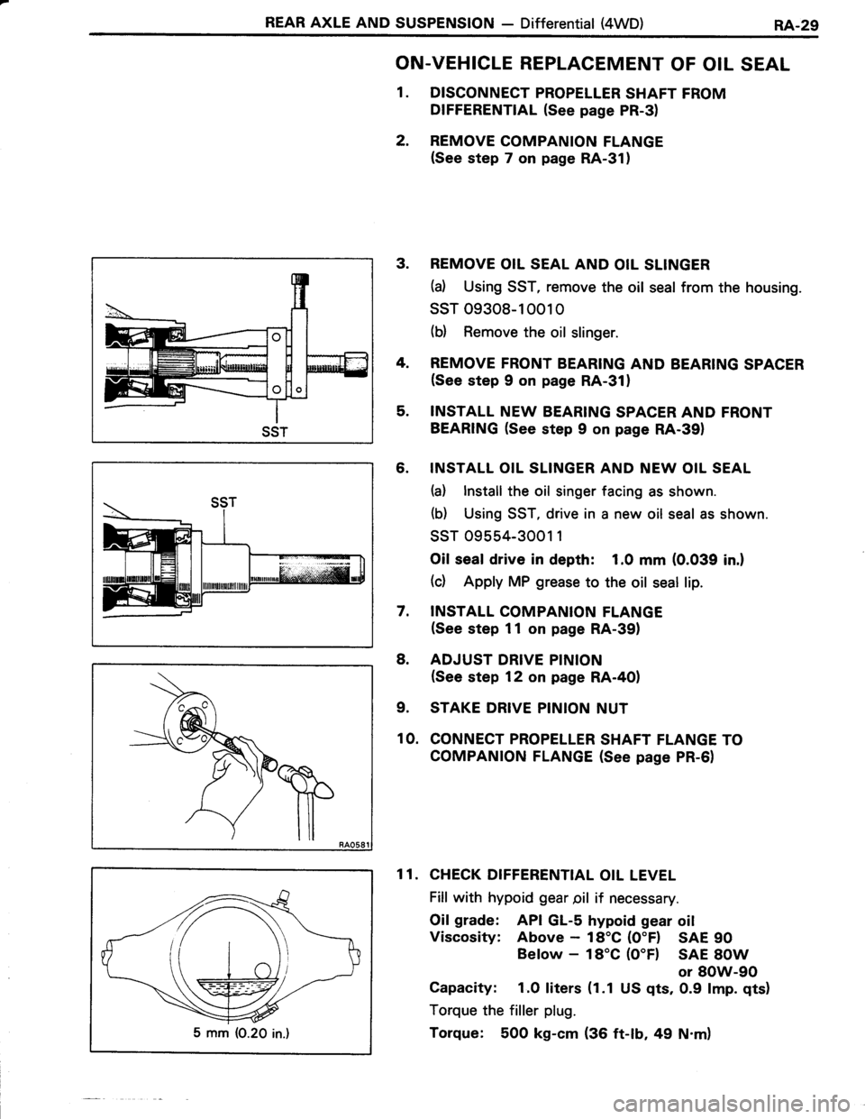
ON.VEHICLE REPLACEMENT OF OIL SEAL
1. DISCONNECT PROPELLER SHAFT FROM
DIFFERENTIAL (See page PR-3)
2. REMOVE COMPANION FLANGE(See step 7 on page RA-31)
3. REMOVE OIL SEAL AND OIL SLINGER
(d Using SST, remove the oil seal from the housing.
ssT 09308-10010
(b) Remove the oil slinger.
4. REMOVE FRONT BEARING AND BEARING SPACER(See step 9 on page RA-311
5. INSTALL NEW BEARING SPACER AND FRONT
BEARING (See step 9 on page RA-391
6. INSTALL OIL SLINGER AND NEW OIL SEAL
(a) lnstall the oil singer facing as shown.
(b) Using SST, drive in a new oil seal as shown.
ssr 09554-3001 1
Oil seal drive in depth: 1.0 mm (0.039 in.l
(c) Apply MP grease to the oil seal lip.
7, INSTALL COMPANION FLANGE(See step 11 on page RA-39)
8. ADJUST DRIVE PINION
(See step 12 on page RA-4OI
9. STAKE DRIVE PINION NUT
10. CONNECT PROPELLER SHAFT FLANGE TO
COMPANION FLANGE (See page PR-6)
1 1. CHECK DIFFERENTIAL OIL LEVEL
Fill with hypoid gear pil if necessary.
Oil grade: API GL-s hypoid gear oil
Viscosity: Above - 18'C (O"F) SAE 90
Below - 18'C (O"Fl SAE 8OW
or 8OW-90
Capacity: 1.O liters (1.1 US qts, 0.9 lmp. qts)
Torque the filler plug.
Torque: 500 kg-cm (36 ft-lb, 49 N.m)5 mm (O.20 in.)
Page 538 of 885
RA.30REAR AXLE AND SUSPENSION - Differential {4WD)
REMOVAL OF DIFFERENTIAL
(See page RA-28)
1. DRAIN DIFFERENTIAL OIL
2. REMOVE REAR AXLE SHAFT (See page RA-25)
3. DISCONNECT PROPELLER SHAFT FROM
DIFFERENTIAL (See page RA-28)
4. REMOVE DIFFERENTIAL CARRIER ASSEMBLY
DISASSEMBLY OF DIFFERENTIAL
(See page RA-281
NOTE: lf the differential is noisy, perform the following
pre-inspection before disassembly to determine the cause.
lf the differential has severe problems, disassemble and
repair as necessary.
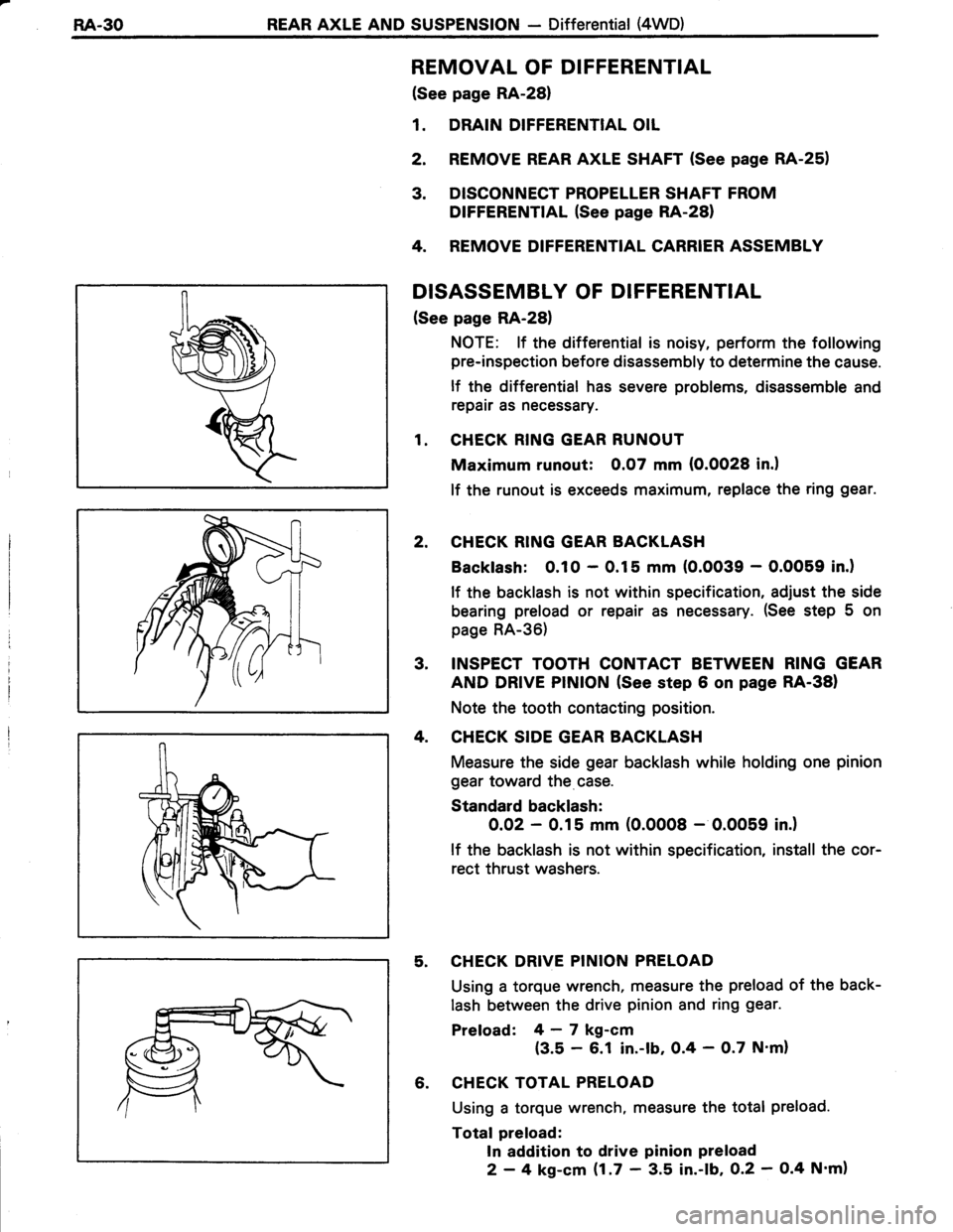
1. CHECK RING GEAR RUNOUT
Maximum runout: 0.07 mm (O.OO28 in.l
lf the runout is exceeds maximum, replace the ring gear.
2. CHECK RING GEAR BACKLASH
Backlash: 0.10 - 0.15 mm (O.OO39 - O.OO59 in.)
lf the backlash is not within specification, adjust the side
bearing preload or repair as necessary. (See step 5 on
page RA-36)
3, INSPECT TOOTH CONTACT BETWEEN RING GEAR
AND DRIVE PINION (See step 6 on page RA-38)
Note the tooth contacting position.
4. CHECK SIDE GEAR BACKLASH
Measure the side gear backlash while holding one pinion
gear toward the case.
Standard backlash:
O.OZ - 0.15 mm (0.0008 - 0.0059 in.)
lf the backlash is not within specification, install the cor-
rect thrust washers.
5. CHECK DRIVE PINION PRELOAD
Using a torque wrench, measure the preload of the back-
lash between the drive pinion and ring gear.
Preload: 4-7 kg-cm
{3.5 - 6.1 in.-lb, 0.4 - O.7 N'm}
6. CHECK TOTAL PRELOAD
Using a torque wrench, measure the total preload.
Total preload:
In addition to drive pinion preload
2 - 4 kg-cm $.7 ' 3.5 in.-lb, O.2 - O.4 N'm)
Page 542 of 885
RA.34REAR AXLE AND SUSPENSION - Differential (4WD)
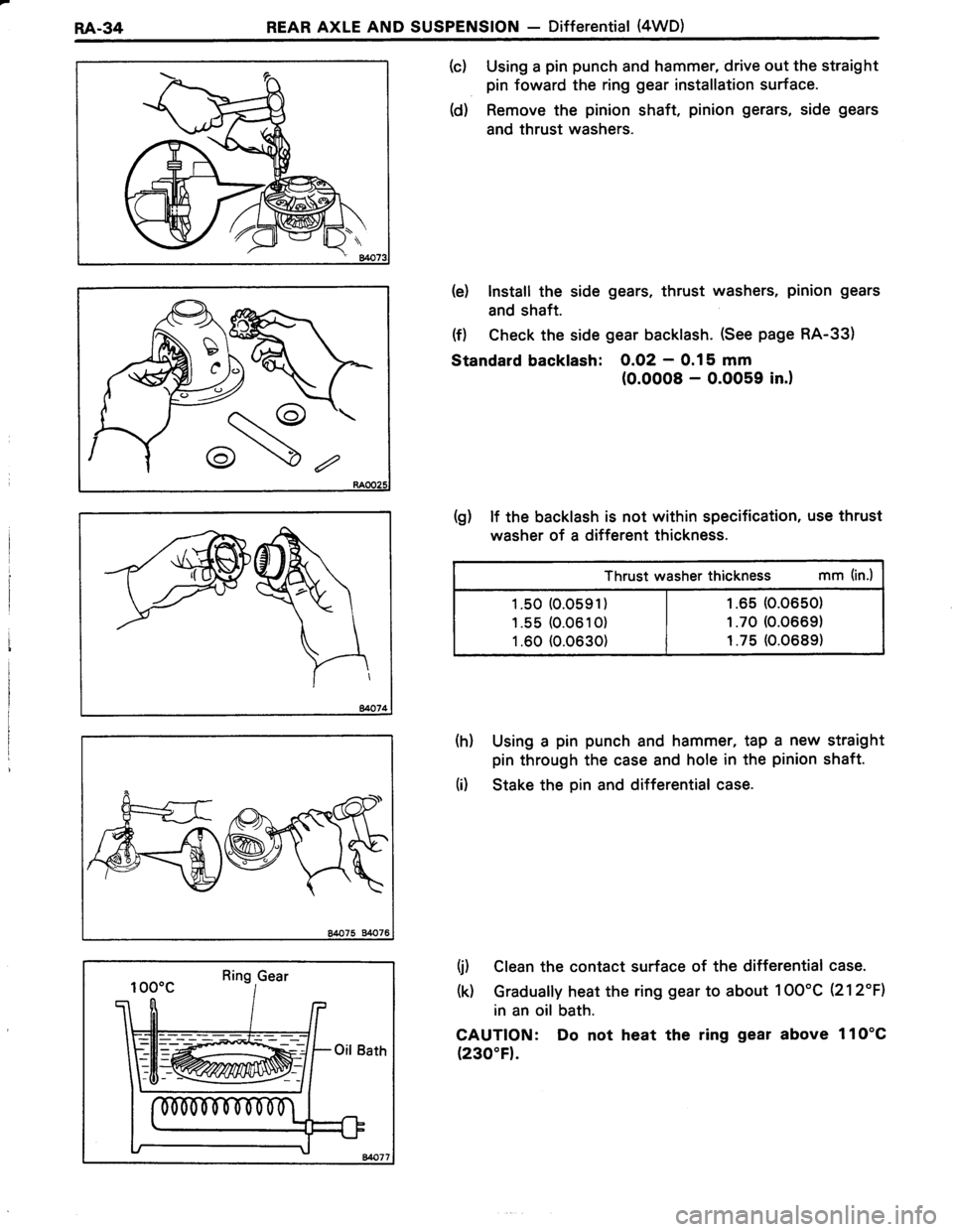
(c) Using a pin punch and hammer, drive out the straight
pin foward the ring gear installation surface.
(d) Remove the pinion shaft, pinion gerars, side gears
and thrust washers.
te) Install the side gears, thrust washers, pinion gears
and shaft.
(f) Check the side gear backlash. (See page RA-33)
Standard backlash: O.O2 - 0.15 mm
(0.0008 - O.OO59 in.)
(g) lf the backlash is not within specification, use thrust
washer of a different thickness.
Thrust washer thickness mm (in.)
1.50 (0.0591) | r.65 (0.0650)
1 .s5 (0.061 0) | t .70 (0.0669)
1.60 (0.0630) | r.75 (0.0689)
(h) Using a pin punch and hammer, tap a new straight
pin through the case and hole in the pinion shaft.
(i) Stake the pin and differential case.
(j) Clean the contact surface of the differential case.
(0 Gradually heat the ring gear to about 1OO'C (212"F1
in an oil bath.
CAUTION: Do not heat the ring gear above 1lO'C
(230"F).
Ring Gear
=-_-
&
Page 543 of 885
REAR AXIE AND SUSPENSION - Differential (4WD)RA-35
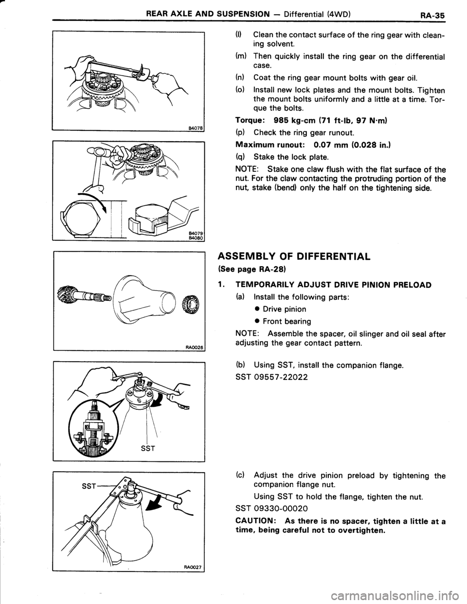
(l) Clean the contact surface of the ring gear with clean-
ing solvent.
(m) Then quickly install the ring gear on the differential
case.
(n) Coat the ring gear mount bolts with gear oil.
(o) Install new lock plates and the mount bolts. Tighten
the mount bolts uniformly and a little at a time. Tor-
que the bolts.
Torque: 985 kg-cm (71 ft-lb, 97 N.m)
(p) Check the ring gear runout.
Maximum runout: 0.07 mm (0.028 in.)
(q) Stake the lock plate.
NOTE: Stake one claw flush with the flat surface of the
nut. For the claw contacting the protruding portion of the
nut, stake (bend) only the half on the tightening side.
ASSEMBLY OF DIFFERENTIAL
(See page RA-28)
1. TEMPORARILY ADJUST DRIVE PINION PRELOAD
(a) lnstall the following parts:
o Drive pinion
o Front bearing
NOTE: Assemble the spacer, oil slinger and oil seal after
adjusting the gear contact pattern.
(b) Using SST, install the companion flange.
ssT 09557-22022
(c) Adjust the drive pinion preload by tightening the
companion flange nut.
Using SST to hold the flange, tighten the nut.
ssT 09330-00020
CAUTION: As there is no spacer, taghten a little at a
time, being careful not to overtighten.
Page 552 of 885
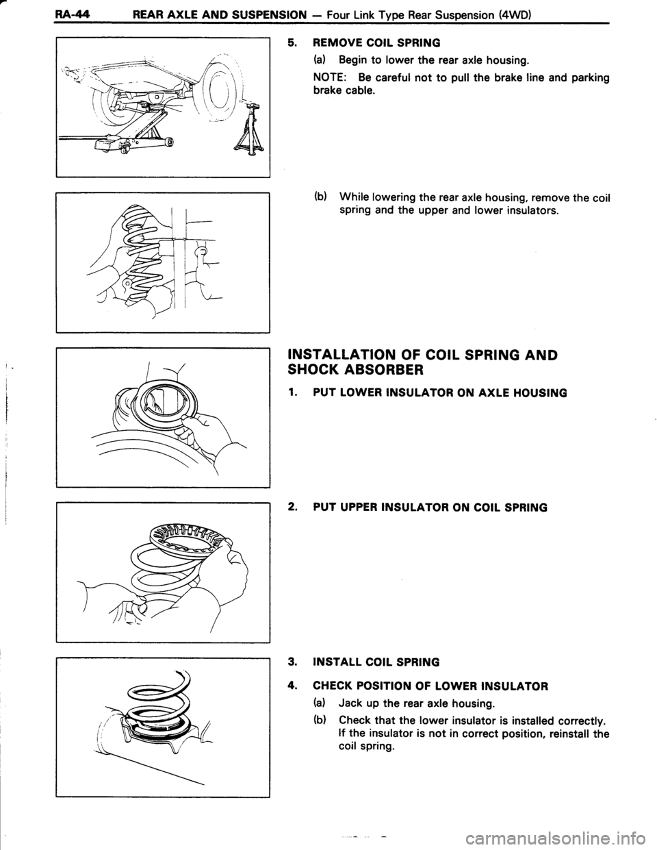
RA-/14 REAR AXLE AND SUSPENSION - Four Link Type Rear Suspension (4WD)
5. REMOVE COIL SPRING
(a) Begin to lower the rear axle housing.
NOTE: Be careful not to pull the brake line and parking
brake cable.
(b) While lowering the rear axle housing, remove the coil
spring and the upper and lower insulators.
INSTALLATION OF COIL SPRING AND
SHOCK ABSORBER
1. PUT LOWER INSULATOR ON AXLE HOUSING
2, PUT UPPER INSULATOR ON COIL SPRING
3. INSTALL COIL SPRING
4. CHECK POSITION OF LOWER INSULATOR
(a) Jack up the rear axle housing.
(b) Check that the lower insulator is installed correctly.
lf the insulator is not in correct position, reinstall the
coil spring.
Page 561 of 885
BR-2BRAKE SYSTEM - Precautions, Troubleshooting
PRECAUTIONS
1. Care must be taken to replace each part properly as it
could affect the performance of the brake system and
result in a driving hazard. Replace the parts with parts
of the same part number or equivalent.
2, ltnis very important to keep parts and the area clean
wltsn repairing the brake system.
TROUBLESHOOTING
ProblemPossible causeRemedyPage
Low or spongy pedalLinings worn
Leak in brake system
Master cylinder faulty
Air in brake system
Wheel cylinder faulty
Piston seals worn or damaged
Rear brake automatic adiuster faulty
Replace brake shoes or pads
Repair leak
Repair or replace master cylinder
Bleed brake system
Repair wheel cylinder
Repair brake calipers
Repair or replace adjuster
BR-16,22
BR-43
BR-9
BR-7
8R.22
BR-1 6
B,R.22
Brakes dragParking brake out of adjustment
Parking brake wire binding
Booster push rod out of adjustment
Return spring faulty
Brake line restricted
Lining cracked or distorted
Wheel cylinder or caliper piston sticking
Automatic adjuster broken
Master cylinder faulty
Adjust parking brake
Repair as necessary
Adjust push rod
Replace spring
Repair as necessary
Replace brake shoe
Repair as necessary
Replace adjuster
Repair or replace master cylinder
BR.8
BR.1 5
BR-22
BR-22
BR-18,22
BR-22
BR-9
Brakes pullTires improperly inflated
Oil or grease on linings
Brake shoes distorted, linings worn or
glazed
Drum or disc out of round
Return spring faulty
Wheel cylinder faulty
Piston frozen in caliper
Disc brake pad sticking
Inflate tires to proper pressure
Check for cause, replace lining
Replace brake shoes
Replace drum or disc
Replace spring
Repair wheel cylinder
Repair caliper
Replace pads
FA-3
BR-16,22
BR-16,22
BR-l8,22
BR-22
BR-18,22
BR.1 8
BR-1 6
Hard pedal but
brakes inefficient
Oil or grbase on linings
Brake shoes distorted, linings worn
or glazed, drums worn
Disc brake pads worn
Piston frozen in caliper
Brake booster faulty
Brake line restricted
Check for cause, replace lining
Replace brake shoes
Replace pads
Repair caliper
Repair booster
Repair as necessary
BR-I6,22
BR-16,22
BR-1 6
BR-1 6
BR.1 4