tow TOYOTA TERCEL 1985 Repair Manual
[x] Cancel search | Manufacturer: TOYOTA, Model Year: 1985, Model line: TERCEL, Model: TOYOTA TERCEL 1985Pages: 885, PDF Size: 64.52 MB
Page 496 of 885

FA-l6FRONT AXLE AND SUSPENSION - Front Drive Shaft
TVinylTape
406 mm r(15.98 in.) |
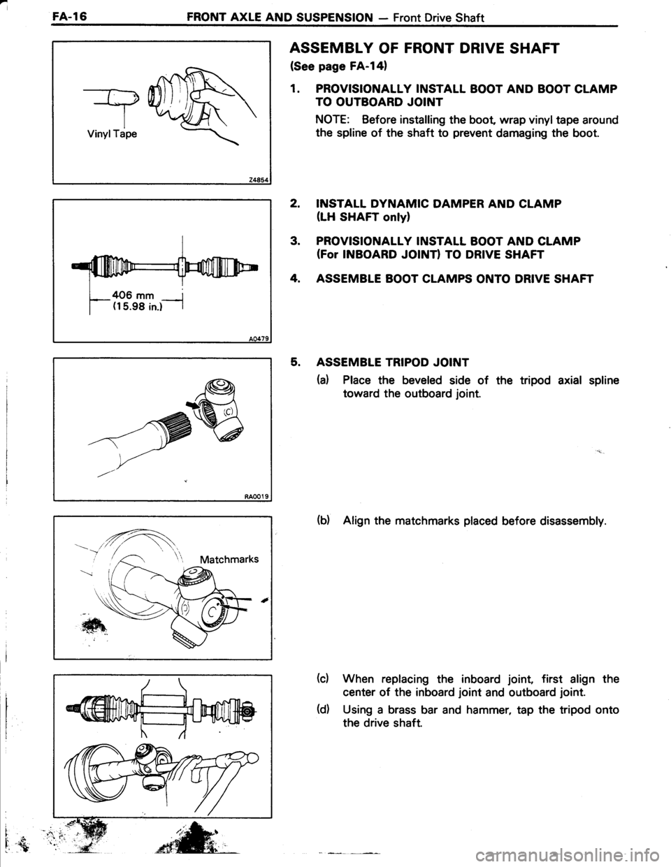
ASSEMBLY OF FRONT DRIVE SHAFT
(See page FA-l41
1. PROVISIONALLY INSTALL BOOT AND BOOT CLAMP
TO OUTBOARD JOINT
NOTE: Before installing the boot wrap vinyltape around
the spline of the shaft to prevent damaging the boot.
INSTALL DYNAMIC DAMPER AND CLAMP
(LH SHAFT onlyl
PROVISIONALLY INSTALL BOOT AND CLAMP(For INBOARD JOINTI TO DRIVE SHAFT
ASSEMBLE BOOT CLAMPS ONTO DRIVE SHAFT
ASSEMBLE TRIPOD JOINT
(a) Place the beveled side of the tripod axial spline
toward the outboard joint.
(b) Align the matchmarks placed before disassembly.
When replacing the inboard joint, first align the
center of the inboard joint and outboard joint.
Using a brass bar and hammer, tap the tripod onto
the drive shaft.
2.
3.
4.
5.
(c)
i
I.{
-^'re
t,-/
(d)
Page 535 of 885

REAR AXLE AND SUSPENSION - Rear Axle Shaft (4WD)RA..27
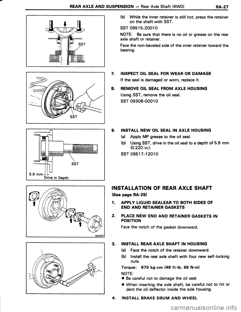
(b) While the inner retainer is still hot, press the retainer
on the shaft with SST.
ssT 0951 5-20010
NOTE: Be sure that there is no oil or grease on the rear
axle shaft or retainer.
Face the non-beveled side of the inner retainer toward the
bearing.
7. INSPECT OIL SEAL FOR WEAR OR DAMAGE
lf the seal is damaged or worn, replace it.
8. REMOVE OIL SEAL FROM AXLE HOUSING
Using SST, remove the oil seal.
ssT 09308-00010
9. INSTALL NEW OIL SEAL IN AXLE HOUSING
(d Apply MP grease to the oil seal.
(b) Using SST, drive in the oil seal to a depth of 5.6 mm
(0.220 ini.
ssr 0951 7-12010
INSTALLATION OF REAR AXLE SHAFT
{See page RA-25}
1. APPIY LIOUID SEALEAR TO BOTH SIDES OF
END AND RETAINER GASKETS
2. PLACE NEW END AND RETAINER GASKETS IN
POSTTtON
Face the notch of the gasket downward.
3. INSTALL REAR AXLE SHAFT IN HOUSING
(a) Face the notch of the retainer downward.
(b) Install the rear axle shaft with four new self-locking
nuts.
Torque: 670 kg-cm (48 ft-tb, 66 N'm)
NOTE:
o Be careful not to damage the oil seal.
o When inserting the axle shaft, be careful not to hit or
dent the oil deflector inside the axle housing.
4. INSTALL BRAKE DRUM AND WHEEL
Drive in
Page 538 of 885

RA.30REAR AXLE AND SUSPENSION - Differential {4WD)
REMOVAL OF DIFFERENTIAL
(See page RA-28)
1. DRAIN DIFFERENTIAL OIL
2. REMOVE REAR AXLE SHAFT (See page RA-25)
3. DISCONNECT PROPELLER SHAFT FROM
DIFFERENTIAL (See page RA-28)
4. REMOVE DIFFERENTIAL CARRIER ASSEMBLY
DISASSEMBLY OF DIFFERENTIAL
(See page RA-281
NOTE: lf the differential is noisy, perform the following
pre-inspection before disassembly to determine the cause.
lf the differential has severe problems, disassemble and
repair as necessary.
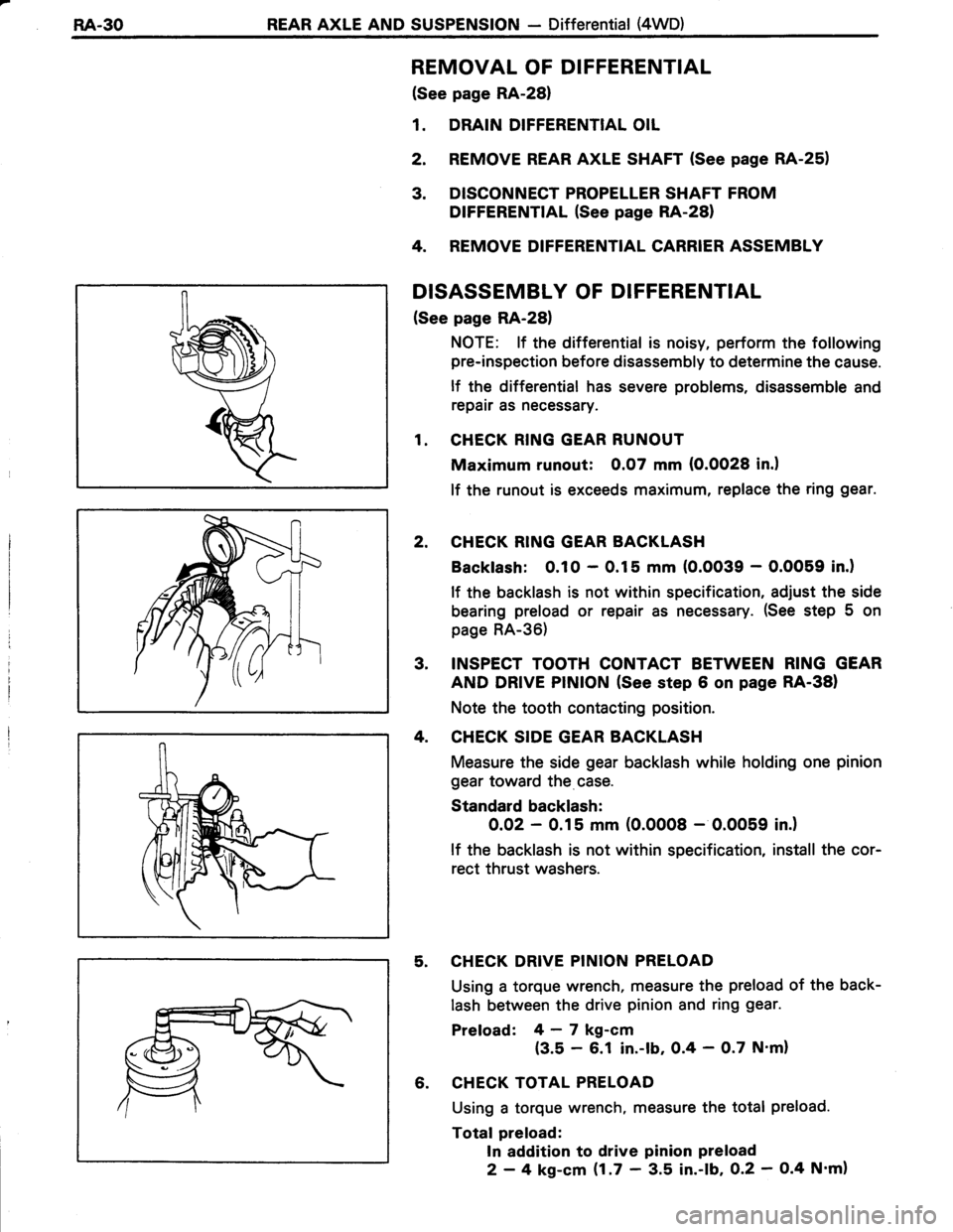
1. CHECK RING GEAR RUNOUT
Maximum runout: 0.07 mm (O.OO28 in.l
lf the runout is exceeds maximum, replace the ring gear.
2. CHECK RING GEAR BACKLASH
Backlash: 0.10 - 0.15 mm (O.OO39 - O.OO59 in.)
lf the backlash is not within specification, adjust the side
bearing preload or repair as necessary. (See step 5 on
page RA-36)
3, INSPECT TOOTH CONTACT BETWEEN RING GEAR
AND DRIVE PINION (See step 6 on page RA-38)
Note the tooth contacting position.
4. CHECK SIDE GEAR BACKLASH
Measure the side gear backlash while holding one pinion
gear toward the case.
Standard backlash:
O.OZ - 0.15 mm (0.0008 - 0.0059 in.)
lf the backlash is not within specification, install the cor-
rect thrust washers.
5. CHECK DRIVE PINION PRELOAD
Using a torque wrench, measure the preload of the back-
lash between the drive pinion and ring gear.
Preload: 4-7 kg-cm
{3.5 - 6.1 in.-lb, 0.4 - O.7 N'm}
6. CHECK TOTAL PRELOAD
Using a torque wrench, measure the total preload.
Total preload:
In addition to drive pinion preload
2 - 4 kg-cm $.7 ' 3.5 in.-lb, O.2 - O.4 N'm)
Page 541 of 885

REAR AXLE AND SUSPENSION - Differential (4WD)RA-33
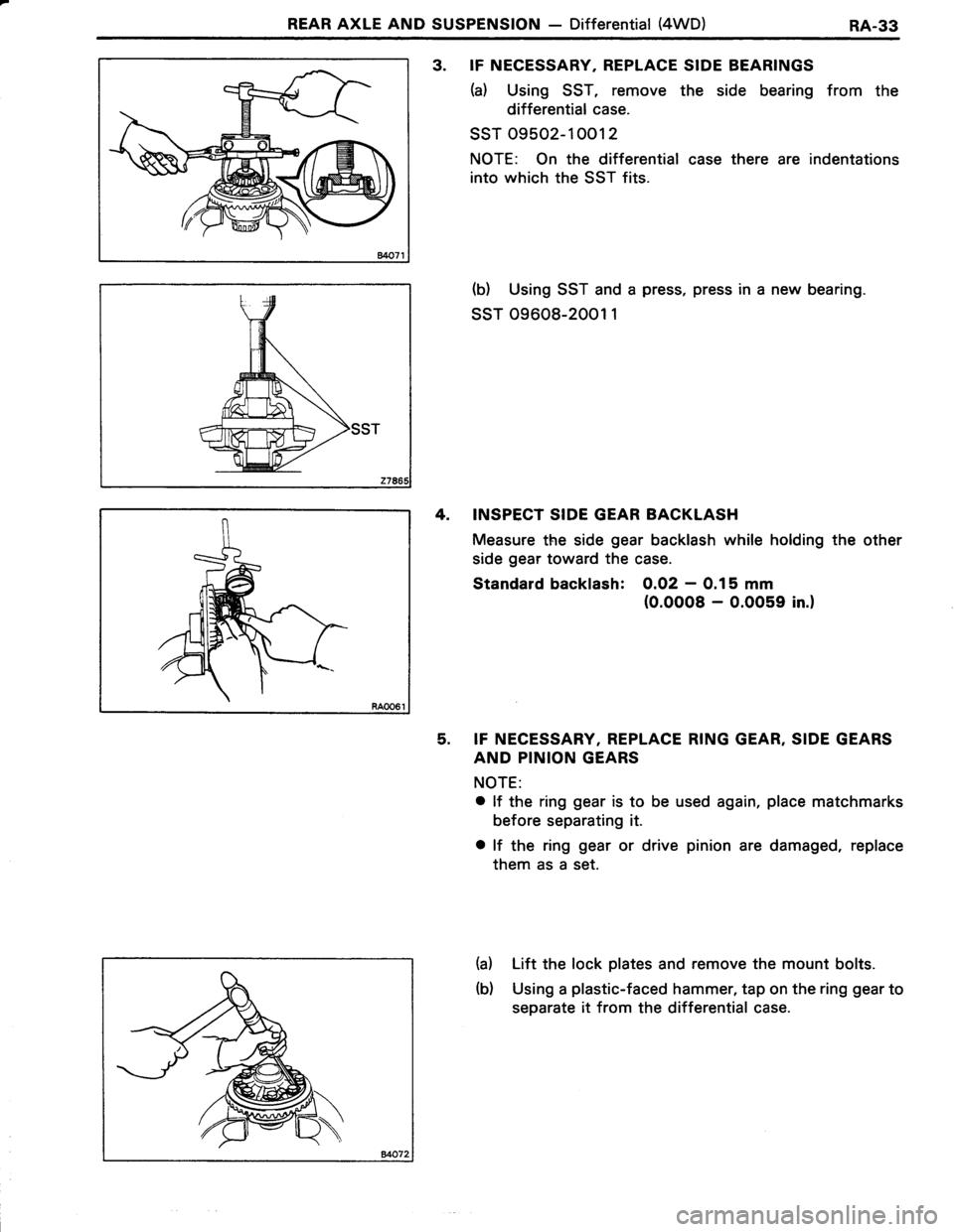
3. IF NECESSARY, REPLACE SIDE BEARINGS
(a) Using SST, remove the side bearing from the
differential case.
ssT 09502-10012
NOTE: On the differential case there are indentations
into which the ssT fits.
(b) Using SST and a press, press in a new bearing.
ssr 09608-2001 1
4. INSPECT SIDE GEAR BACKLASH
Measure the side gear backlash while holding the other
side gear toward the case.
Standard backlash: 0.02 - 0.15 mm
(0.0008 - 0.0059 in.)
5. IF NECESSARY, REPLACE RING GEAR, SIDE GEARS
AND PINION GEARS
NOTE:
o lf the ring gear is to be used again, place matchmarks
before separating it.
o lf the ring gear or drive pinion are damaged, replace
them as a set.
(a) Lift the lock plates and remove the mount bolts.
(b) Using a plastic-faced hammer, tap on the ring gear to
separate it from the differential case.