steering wheel adjustment TOYOTA TUNDRA 2018 Owners Manual (in English)
[x] Cancel search | Manufacturer: TOYOTA, Model Year: 2018, Model line: TUNDRA, Model: TOYOTA TUNDRA 2018Pages: 672, PDF Size: 14.09 MB
Page 125 of 672

1253-3. Adjusting the seats
3
Operation of each component
■Power easy access system (vehicles with driving position memory )
The driver’s seat and steering wheel move in accordance with en gine switch
position and the driver’s seat belt condition. ( P. 128)
WARNING
■When adjusting the seat position
● Take care when adjusting the seat position to ensure that other passen-
gers are not injured by the moving seat.
● Do not put your hands under the seat or near the moving parts t o avoid
injury.
Fingers or hands may become jammed in the seat mechanism.
■ Seat adjustment
● To reduce the risk of sliding under the lap belt during a collision, do not
recline the seat more than necessary.
If the seat is too reclined, the lap belt may slide past the hi ps and apply
restraint forces directly to the abdomen, or your neck may cont act the
shoulder belt, increasing the risk of death or serious injury in the event of
an accident.
Adjustments should not be made while driving as the seat may un expect-
edly move and cause the driver to lose control of the vehicle.
● Manual seat type only: After adjusting the seat, make sure that the seat is
locked in position.
■ When adjusting the seat positions
Make sure to leave enough space around the feet so they do not get stuck.
Page 130 of 672

1303-3. Adjusting the seats
■To stop the position recall operation part-way through
Perform any of the following:
●Press the “SET” button.
● Press button “1” or “2”.
● Operate any of the seat adjustment switches (only cancels seat position
recall).
● Operate the tilt and telescopic steering control switch (only cancels steering
wheel position recall).
■ Seat positions that can be memorized ( P. 123)
The adjusted seat positions can be recorded except for lumbar s upport posi-
tions.
■ Operating the driving position me mory after the key is removed from the
engine switch
Recorded seat positions (except the steering wheel position) can be activated
up to 30 seconds after the driver’s door is opened, even if the key is removed
from the engine switch.
■ In order to correctly use the dr iving position memory function
If a seat position is already in the furthest possible position and the seat is
operated in the same direction, the recorded position may be sl ightly different
when it is recalled.
Page 131 of 672
1313-3. Adjusting the seats
3
Operation of each component
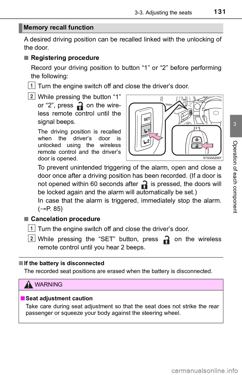
A desired driving position can be recalled linked with the unlo cking of
the door.
■Registering procedure
Record your driving position to button “1” or “2” before perfor ming
the following:
Turn the engine switch off and close the driver’s door.
While pressing the button “1”
or “2”, press on the wire-
less remote control until the
signal beeps.
The driving position is recalled
when the driver’s door is
unlocked using the wireless
remote control and the driver’s
door is opened.
To prevent unintended triggering of the alarm, open and close a
door once after a driving position has been recorded. (If a doo r is
not opened within 60 seconds after is pressed, the doors will
be locked again and the alarm will au tomatically be set.)
In case that the alarm is triggered, immediately stop the alarm .
( P. 85)
■Cancelation procedure
Turn the engine switch off and close the driver’s door.
While pressing the “SET” button, press on the wireless
remote control until you hear 2 beeps.
■ If the battery is disconnected
The recorded seat positions are erased when the battery is disc onnected.
Memory recall function
1
2
WARNING
■Seat adjustment caution
Take care during seat adjustment so that the seat does not stri ke the rear
passenger or squeeze your body against the steering wheel.
1
2
Page 136 of 672
1363-4. Adjusting the steering wheel and mirrors
Steering wheel
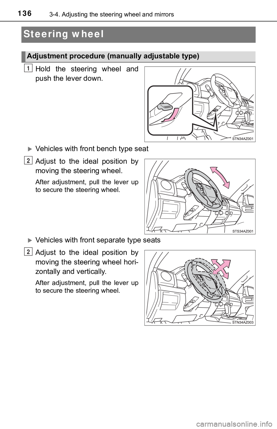
Hold the steering wheel and
push the lever down.
Vehicles with front bench type seat
Adjust to the ideal position by
moving the steering wheel.
After adjustment, pull the lever up
to secure the steering wheel.
Vehicles with front separate type seats
Adjust to the ideal position by
moving the steering wheel hori-
zontally and vertically.
After adjustment, pull the lever up
to secure the steering wheel.
Adjustment procedure (manually adjustable type)
1
2
2
Page 137 of 672
1373-4. Adjusting the steering wheel and mirrors
3
Operation of each component
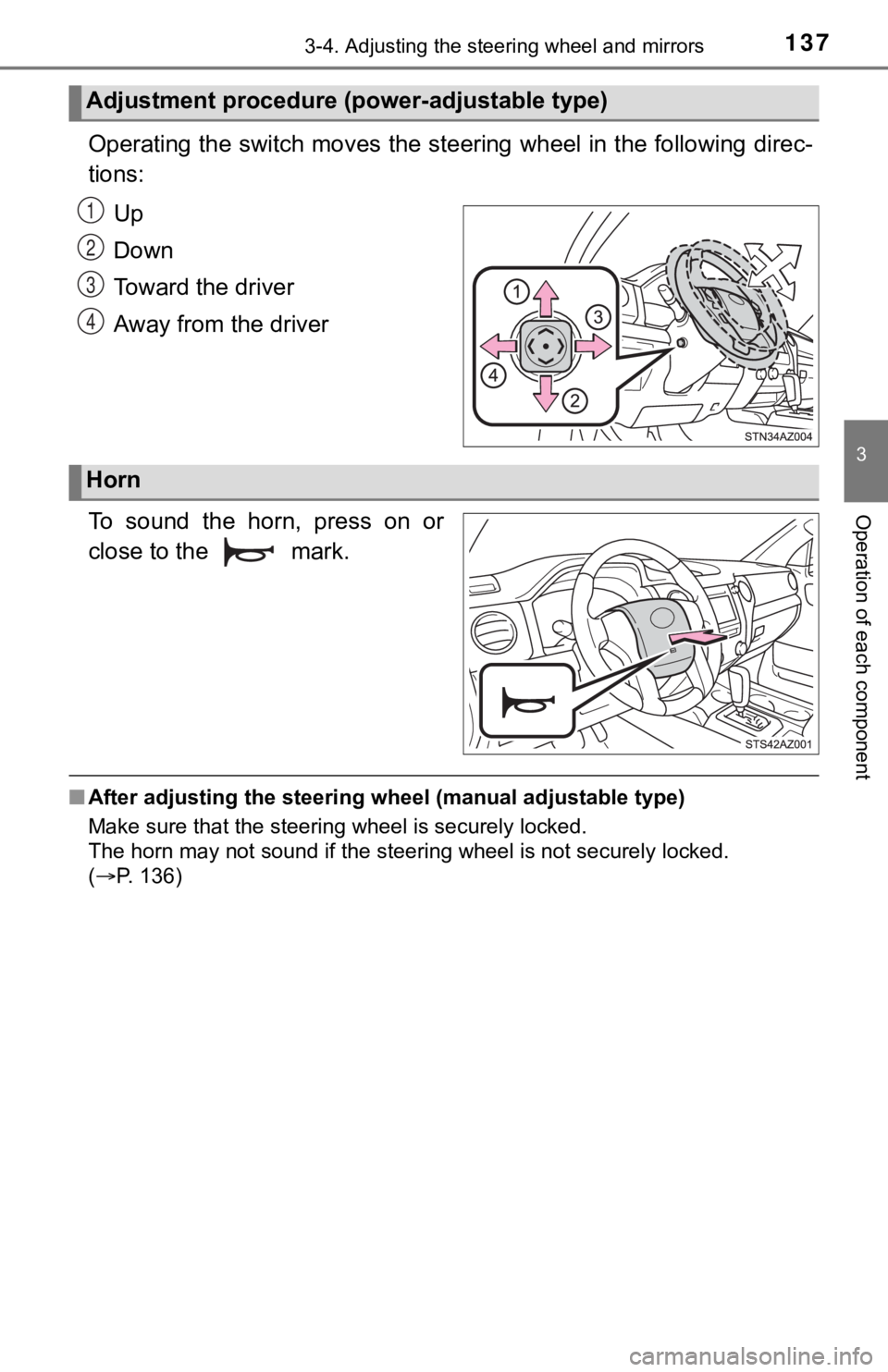
Operating the switch moves the steering wheel in the following direc-
tions:
Up
Down
Toward the driver
Away from the driver
To sound the horn, press on or
close to the mark.
■ After adjusting the steering wheel (manual adjustable type)
Make sure that the steering wheel is securely locked.
The horn may not sound if the steer ing wheel is not securely locked.
( P. 136)
Adjustment procedure (power-adjustable type)
1
2
3
4
Horn
Page 138 of 672
1383-4. Adjusting the steering wheel and mirrors
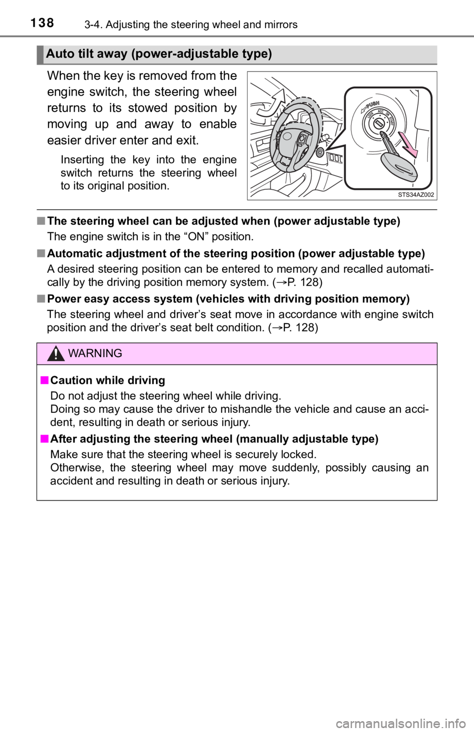
When the key is removed from the
engine switch, the steering wheel
returns to its stowed position by
moving up and away to enable
easier driver enter and exit.
Inserting the key into the engine
switch returns the steering wheel
to its original position.
■The steering wheel can be adjusted when (power adjustable type)
The engine switch is in the “ON” position.
■ Automatic adjustment of the stee ring position (power adjustable type)
A desired steering position can be entered to memory and recall ed automati-
cally by the driving position memory system. ( P. 128)
■ Power easy access system (vehicles with driving position memory )
The steering wheel and driver’s seat move in accordance with en gine switch
position and the driver’s seat belt condition. ( P. 128)
Auto tilt away (power-adjustable type)
WARNING
■Caution while driving
Do not adjust the steering wheel while driving.
Doing so may cause the driver to mishandle the vehicle and caus e an acci-
dent, resulting in death or serious injury.
■ After adjusting the steering wheel (manually adjustable type)
Make sure that the steering wheel is securely locked.
Otherwise, the steering wheel may move suddenly, possibly causi ng an
accident and resulting in death or serious injury.
Page 142 of 672
1423-4. Adjusting the steering wheel and mirrors
Outside rear view mirrors
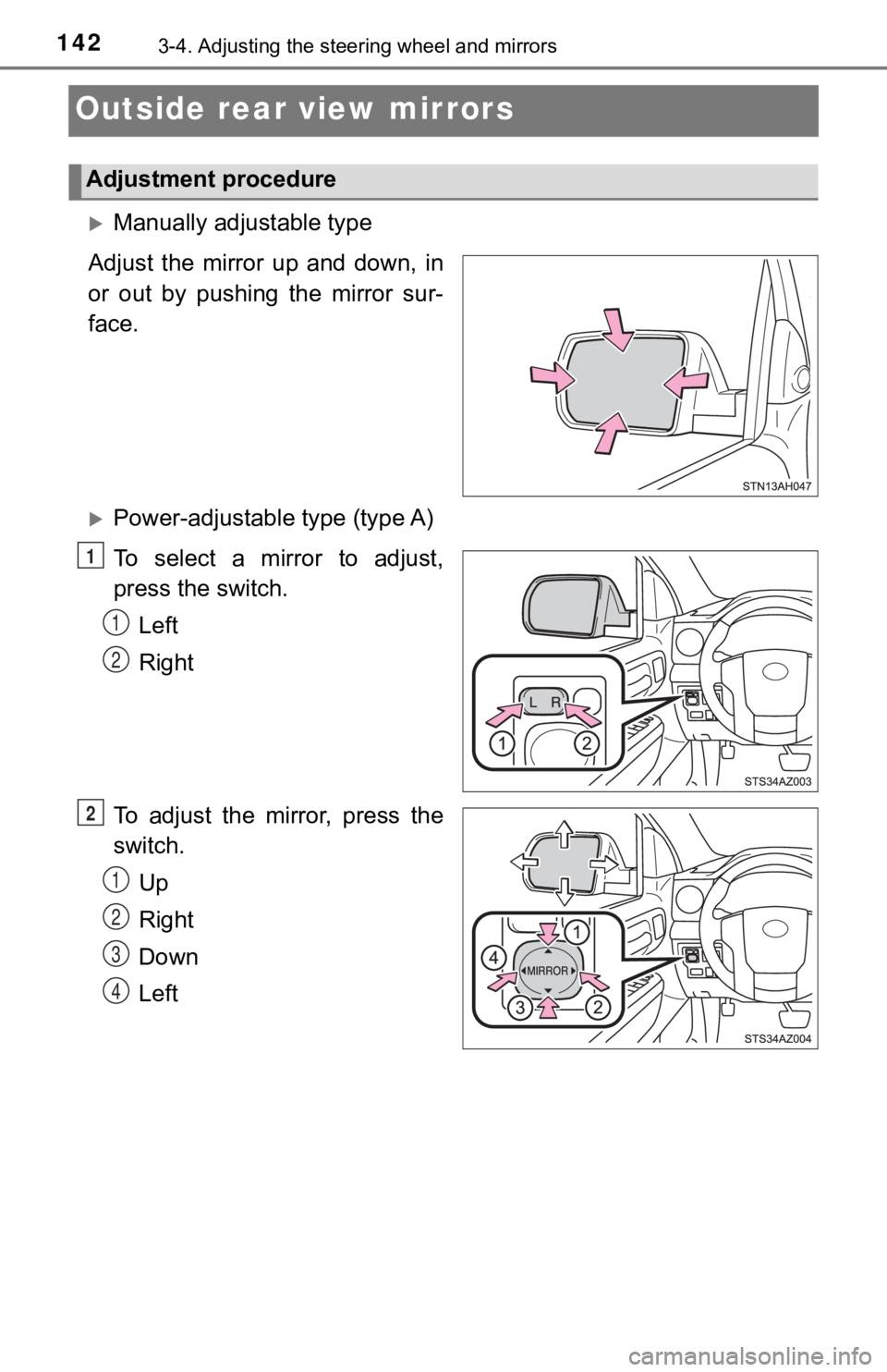
Manually adjustable type
Adjust the mirror up and down, in
or out by pushing the mirror sur-
face.
Power-adjustable type (type A)
To select a mirror to adjust,
press the switch. Left
Right
To adjust the mirror, press the
switch. Up
Right
Down
Left
Adjustment procedure
1
1
2
2
1
2
3
4
Page 144 of 672
1443-4. Adjusting the steering wheel and mirrors
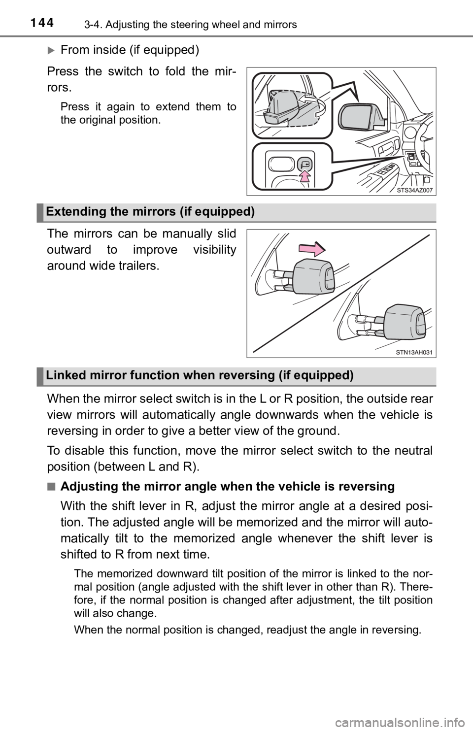
From inside (if equipped)
Press the switch to fold the mir-
rors.
Press it again to extend them to
the original position.
The mirrors can be manually slid
outward to improve visibility
around wide trailers.
When the mirror select switch is in the L or R position, the ou tside rear
view mirrors will automatically a ngle downwards when the vehicl e is
reversing in order to give a better view of the ground.
To disable this function, move the mirror select switch to the neutral
position (between L and R).
■Adjusting the mirror angle when the vehicle is reversing
With the shift lever in R, adjust the mirror angle at a desired posi-
tion. The adjusted angle will be memorized and the mirror will auto-
matically tilt to the memorized angle whenever the shift lever is
shifted to R from next time.
The memorized downward tilt position of the mirror is linked to the nor-
mal position (angle adjusted with the shift lever in other than R). There-
fore, if the normal position is changed after adjustment, the t ilt position
will also change.
When the normal position is changed, readjust the angle in reve rsing.
Extending the mirrors (if equipped)
Linked mirror function when reversing (if equipped)
Page 145 of 672
1453-4. Adjusting the steering wheel and mirrors
3
Operation of each component
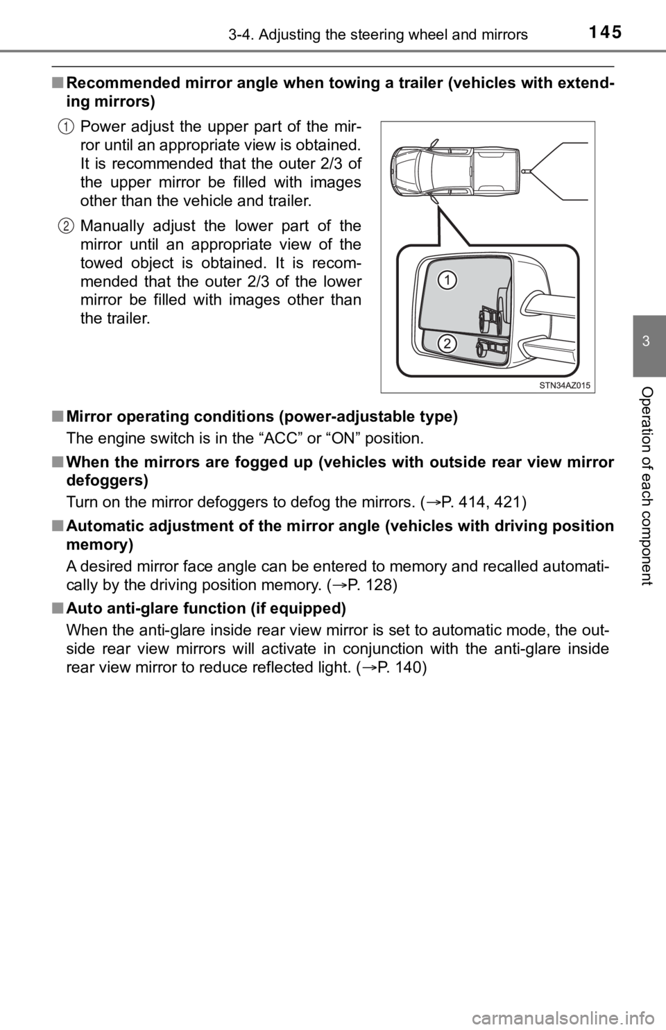
■Recommended mirror angle when to wing a trailer (vehicles with extend-
ing mirrors)
■ Mirror operating conditions (power-adjustable type)
The engine switch is in the “ACC” or “ON” position.
■ When the mirrors are fogged up ( vehicles with outside rear view mirror
defoggers)
Turn on the mirror defoggers to defog the mirrors. ( P. 414, 421)
■ Automatic adjustment of the mirr or angle (vehicles with driving position
memory)
A desired mirror face angle can be entered to memory and recall ed automati-
cally by the driving position memory. ( P. 128)
■ Auto anti-glare function (if equipped)
When the anti-glare inside rear view mirror is set to automatic mode, the out-
side rear view mirrors will activate in conjunction with the an ti-glare inside
rear view mirror to reduce reflected light. ( P. 140)
Power adjust the upper part of the mir-
ror until an appropriate view is obtained.
It is recommended that the outer 2/3 of
the upper mirror be filled with images
other than the vehicle and trailer.
Manually adjust the lower part of the
mirror until an appropriate view of the
towed object is obtained. It is recom-
mended that the outer 2/3 of the lower
mirror be filled with images other than
the trailer.
1
2
Page 553 of 672

5538-2. Steps to take in an emergency
8
When trouble arises
WARNING
■If both the ABS and the brake s ystem warning lights remain on
Stop your vehicle in a safe place immediately and contact your To y o t a
dealer. The vehicle will become extremely unstable during braki ng, and the
ABS system may fail, which could cause an accident resulting in death or
serious injury.
■ If the tire pressure warning light comes on
Be sure to observe the following precautions. Failure to do so could cause a
loss of vehicle control and result in death or serious injury.
● Stop your vehicle in a safe place as soon as possible. Adjust the tire infla-
tion pressure immediately.
● If the tire pressure warning light comes on even after tire inf lation pressure
adjustment, it is probable that you have a flat tire. Check the tires. If a tire
is flat, change it with the spare tire and have the flat tire repaired by the
nearest Toyota dealer.
● Avoid abrupt maneuvering and braking. If the vehicle tires deteriorate, you
could lose control of the steering wheel or the brakes.
■ If a blowout or sudden air leakage should occur
The tire pressure warning system may not activate immediately.
■
Maintenance of the tires
Each tire, including the spare (if provided), should be checked monthly
when cold and inflated to the inflation pressure recommended by the
vehicle manufacturer on the vehicle placard or tire inflation p ressure
label (tire and load information label). (If your vehicle has t ires of a dif-
ferent size than the size indica ted on the vehicle placard or tire inflation
pressure label [tire and load information label], you should de termine
the proper tire inflation p ressure for those tires.)
As an added safety feature, your vehicle has been equipped with a tire
pressure monitoring system (TPMS -tire pressure warning system) that
illuminates a low tire pressure telltale (tire pressure warning light) when
one or more of your tires is significantly under-inflated. Acco rdingly,
when the low tire pressure telltale (tire pressure warning ligh t) illumi-
nates, you should stop and check your tires as soon as possible , and
inflate them to the proper pressure. Driving on a significantly under-
inflated tire causes the tire to overheat and can lead to tire failure.
Under-inflation also reduces fuel efficiency and tire tread lif e, and may
affect the vehicle’s handl ing and stopping ability.