tire pressure TOYOTA TUNDRA 2018 Owners Manual (in English)
[x] Cancel search | Manufacturer: TOYOTA, Model Year: 2018, Model line: TUNDRA, Model: TOYOTA TUNDRA 2018Pages: 672, PDF Size: 14.09 MB
Page 6 of 672

TABLE OF CONTENTS6
7-1. Maintenance and careCleaning and protecting the vehicle exterior .......... 470
Cleaning and protecting the vehicle interior ........... 473
7-2. Maintenance Maintenance requirements ................... 476
General maintenance ........ 478
Emission inspection and maintenance (I/M)
programs ......................... 481
7-3. Do-it-yourself maintenance Do-it-yourself service precautions ..................... 482
Hood.................................. 484
Engine compartment ......... 485
Tires .................................. 495
Tire inflation pressure........ 507
Wheels .............................. 510
Air conditioning filter .......... 513
Wireless remote control battery ............................. 516
Checking and replacing fuses ............................... 518
Light bulbs ......................... 521 8-1. Essential information
Emergency flashers ........... 538
If your vehicle has to be stopped in
an emergency.................. 539
8-2. Steps to take in an emergency
If your vehicle needs to be towed .......................... 540
If you think something is wrong............................... 545
Fuel pump shut off system ............................. 546
If a warning light turns on or a warning buzzer
sounds ............................. 547
If a warning message is displayed ......................... 555
If you have a flat tire .......... 565
If the engine will not start ................................. 580
If the vehicle battery is discharged ....................... 582
If your vehicle overheats.... 585
If the vehicle becomes stuck ................................ 588
7Maintenance and care8When trouble arises
Page 15 of 672
15Pictorial index
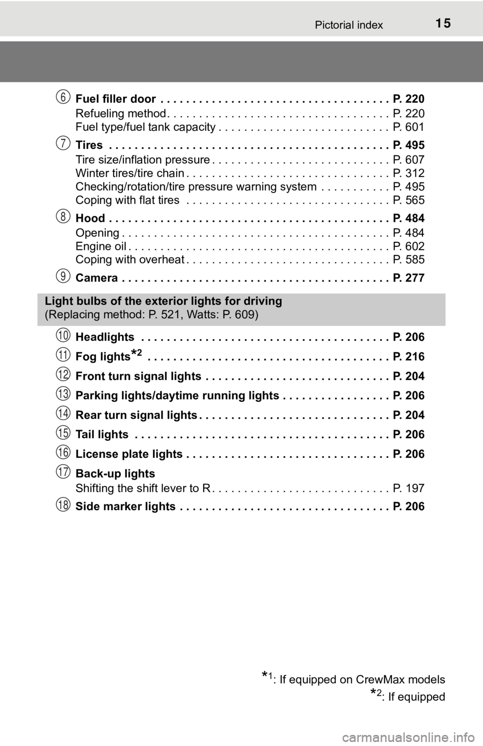
Fuel filler door . . . . . . . . . . . . . . . . . . . . . . . . . . . . . . . . . . . . P. 220
Refueling method . . . . . . . . . . . . . . . . . . . . . . . . . . . . . . . . . . . P. 220
Fuel type/fuel tank capacity . . . . . . . . . . . . . . . . . . . . . . . . . . . P. 601
Tires . . . . . . . . . . . . . . . . . . . . . . . . . . . . . . . . . . . . . . . . . . . . P. 495
Tire size/inflation pressure . . . . . . . . . . . . . . . . . . . . . . . . . . . . P. 607
Winter tires/tire chain . . . . . . . . . . . . . . . . . . . . . . . . . . . . . . . . P. 312
Checking/rotation/tire pressure warning system . . . . . . . . . . . P. 495
Coping with flat tires . . . . . . . . . . . . . . . . . . . . . . . . . . . . . . . . P. 565
Hood . . . . . . . . . . . . . . . . . . . . . . . . . . . . . . . . . . . . . . . . . . . . P. 484
Opening . . . . . . . . . . . . . . . . . . . . . . . . . . . . . . . . . . . . . . . . . . P. 484
Engine oil . . . . . . . . . . . . . . . . . . . . . . . . . . . . . . . . . . . . . . . . . P. 602
Coping with overheat . . . . . . . . . . . . . . . . . . . . . . . . . . . . . . . . P. 585
Camera . . . . . . . . . . . . . . . . . . . . . . . . . . . . . . . . . . . . . . . . . . P. 277
Headlights . . . . . . . . . . . . . . . . . . . . . . . . . . . . . . . . . . . . . . . P. 206
Fog lights
*2 . . . . . . . . . . . . . . . . . . . . . . . . . . . . . . . . . . . . . . P. 216
Front turn signal lights . . . . . . . . . . . . . . . . . . . . . . . . . . . . . P. 204
Parking lights/daytime running lights . . . . . . . . . . . . . . . . . P. 206
Rear turn signal lights . . . . . . . . . . . . . . . . . . . . . . . . . . . . . . P. 204
Tail lights . . . . . . . . . . . . . . . . . . . . . . . . . . . . . . . . . . . . . . . . P. 206
License plate lights . . . . . . . . . . . . . . . . . . . . . . . . . . . . . . . . P. 206
Back-up lights
Shifting the shift lever to R . . . . . . . . . . . . . . . . . . . . . . . . . . . . P. 197
Side marker lights . . . . . . . . . . . . . . . . . . . . . . . . . . . . . . . . . P. 206
6
7
8
9
Light bulbs of the exter ior lights for driving
(Replacing method: P. 521, Watts: P. 609)
*1: If equipped on CrewMax models
*2: If equipped
10
11
12
13
14
15
16
17
18
Page 22 of 672
22Pictorial index
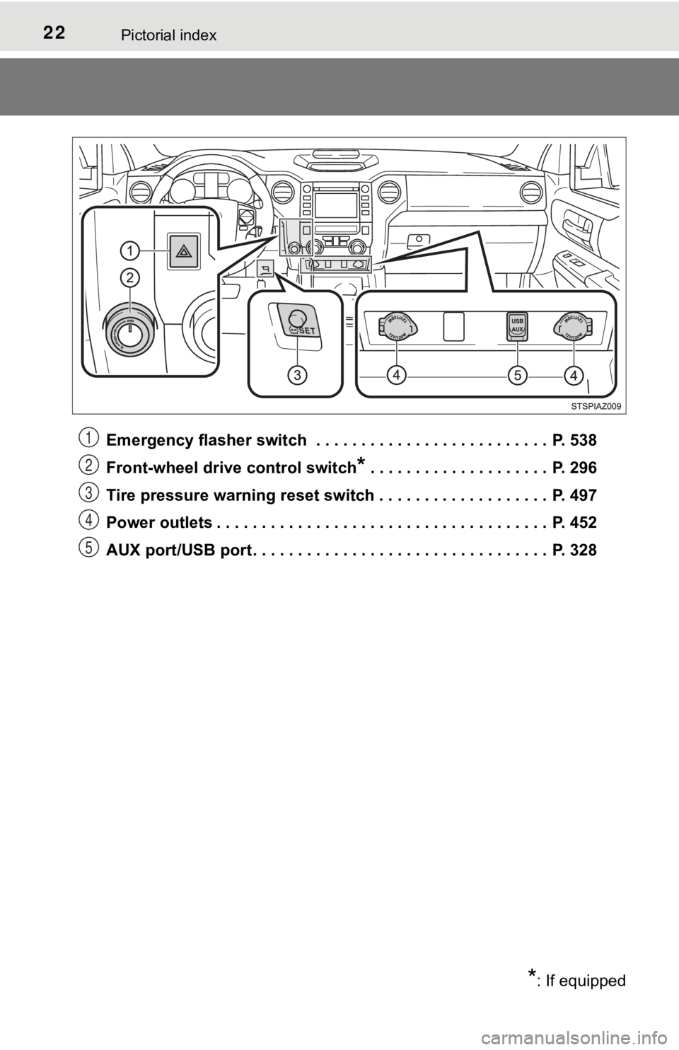
Emergency flasher switch . . . . . . . . . . . . . . . . . . . . . . . . . . P. 538
Front-wheel drive control switch
* . . . . . . . . . . . . . . . . . . . . P. 296
Tire pressure warning reset switch . . . . . . . . . . . . . . . . . . . P. 497
Power outlets . . . . . . . . . . . . . . . . . . . . . . . . . . . . . . . . . . . . . P. 452
AUX port/USB port . . . . . . . . . . . . . . . . . . . . . . . . . . . . . . . . . P. 328
*: If equipped
1
2
3
4
5
Page 91 of 672
912. Instrument cluster
2
Instrument cluster
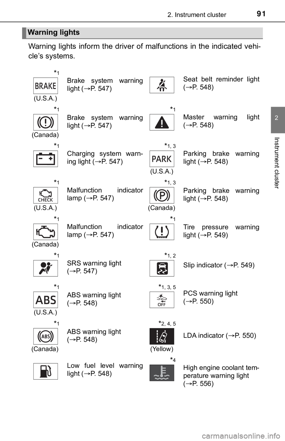
Warning lights inform the driver of malfunctions in the indicated vehi-
cle’s systems.
Warning lights
*1
(U.S.A.)
Brake system warning
light ( P. 547)Seat belt reminder light
(P. 548)
*1
(Canada)
Brake system warning
light ( P. 547)
*1
Master warning light
(P. 548)
*1
Charging system warn-
ing light ( P. 547)
*1, 3
(U.S.A.)
Parking brake warning
light (P. 548)
*1
(U.S.A.)
Malfunction indicator
lamp ( P. 547)
*1, 3
(Canada)
Parking brake warning
light (P. 548)
*1
(Canada)
Malfunction indicator
lamp ( P. 547)
*1
Tire pressure warning
light (P. 549)
*1
SRS warning light
(P. 547)
*1, 2
Slip indicator ( P. 549)
*1
(U.S.A.)
ABS warning light
(P. 548)
*1, 3, 5PCS warning light
(P. 550)
*1
(Canada)
ABS warning light
(P. 548)
*2, 4, 5
(Yellow)
LDA indicator ( P. 550)
Low fuel level warning
light (P. 548)*4
High engine coolant tem-
perature warning light
(P. 556)
Page 100 of 672
1002. Instrument cluster
Multi-infor mation display
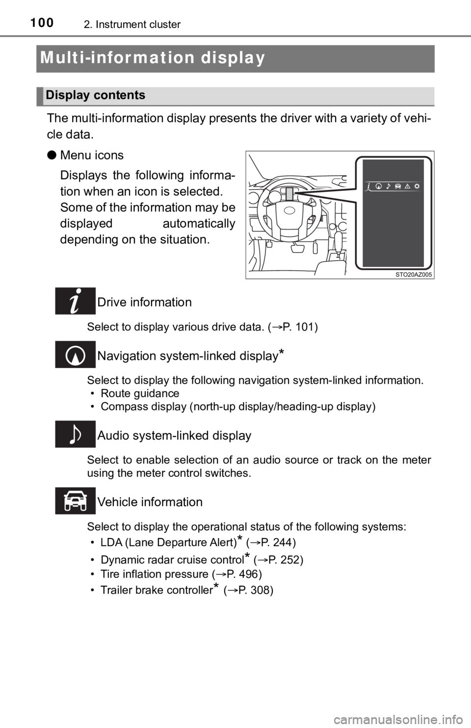
The multi-information display presents the driver with a variety of vehi-
cle data.
● Menu icons
Displays the following informa-
tion when an icon is selected.
Some of the information may be
displayed automatically
depending on the situation.
Drive information
Select to display various drive data. ( P. 101)
Navigation system-linked display*
Select to display the following navigation system-linked information.
• Route guidance
• Compass display (north-up display/heading-up display)
Audio system-linked display
Select to enable selection of an audio source or track on the m eter
using the meter control switches.
Vehicle information
Select to display the operational status of the following syste ms:
• LDA (Lane Departure Alert)
* ( P. 244)
• Dynamic radar cruise control
* ( P. 252)
• Tire inflation pressure ( P. 496)
• Trailer brake controller
* ( P. 308)
Display contents
Page 105 of 672

1052. Instrument cluster
2
Instrument cluster
■Setting items
●“Vehicle Settings” and “Meter Settings” setting items are not s electable
during driving and cannot be operated.
Also, the settings screen is temporarily canceled in the follow ing situations.
• When a warning message appears.
• When the vehicle begins to move.
● Settings for functions not equipped to the vehicle are not displayed.
● When a function is turned off, the related settings for that fu nction are not
selectable.
■ Pop-up display
In some situations, such as when a switch operation is performe d, a pop-up
display will be temporarily displayed on the multi-information display.
■ When disconnecting and reco nnecting battery terminals
The drive information will be reset.
■ Trip summary display
When the engine switch is turned off, each of the following wil l be displayed
on the multi-information display, and will clear after approximately 30 sec-
onds.
● Distance traveled
● Average fuel consumption
● Driving range
■ Tire inflation pressure
●It may take a few minutes to display the tire inflation pressur e after the
engine switch is turned to the “ON” position. It may also take a few minutes
to display the tire inflation pressure after inflation pressure has been
adjusted.
● “---” may be displayed if the tire position information cannot be determined
due to unfavorable radio wave conditions.
● Tire inflation pressure changes with temperature. The displayed values may
also be different from the values measured using a tire pressur e gauge.
■ Liquid crystal display
Small spots or light spots may appear on the display. This phen omenon is
characteristic of liquid crystal displays, and there is no prob lem continuing to
use the display.
Page 242 of 672

2424-5. Using the driving support systems
●In some situations such as the following, sufficient braking fo rce may not be
obtained, preventing the system from performing properly:
• If the braking functions cannot operate to their full extent, such as when
the brake parts are extremely cold, extremely hot, or wet
• If the vehicle is not properly maintained (brakes or tires are excessively
worn, improper tire inflation pressure, etc.)
• When the vehicle is being driven on a gravel road or other sli ppery sur-
face
● Some pedestrians such as the following may not be detected by t he radar
sensor and camera sensor, preventing the system from operating properly:
• Pedestrians shorter than approximately 3.2 ft. (1 m) or taller than approx-
imately 6.5 ft. (2 m)
• Pedestrians wearing oversized clothing (a rain coat, long skir t, etc.), mak-
ing their silhouette obscure
• Pedestrians who are carrying large baggage, holding an umbrell a, etc.,
hiding part of their body
• Pedestrians who are bending forward or squatting
• Pedestrians who are pushing a stroller, wheelchair, bicycle or other vehi-
cle
• Groups of pedestrians which are close together
• Pedestrians who are wearing white and look extremely bright
• Pedestrians in the dark, such as at night or while in a tunnel
• Pedestrians whose clothing appears to be nearly the same color or
brightness as their surroundings
• Pedestrians near walls, fences, guardrails, or large objects
• Pedestrians who are on a metal object (manhole cover, steel plate, etc.) on the road
• Pedestrians who are walking fast
• Pedestrians who are changing speed abruptly
• Pedestrians running out from beh ind a vehicle or a large object
• Pedestrians who are extremely close to the side of the vehicle (outside rear view mirror, etc.)
Page 250 of 672

2504-5. Using the driving support systems
■Conditions in which function s may not operate properly
In the following situations, the camera sensor may not detect w hite (yellow)
lines and various functions may not operate normally.
● There are shadows on the road that run parallel with, or cover, the white
(yellow) lines.
● The vehicle is driven in an area without white (yellow) lines, such as in front
of a tollgate or checkpoint, or at an intersection, etc.
● The white (yellow) lines are cracked, “Botts’ dots”, “Raised pa vement
marker” or stones are present.
● The white (yellow) lines cannot be seen or are difficult to see due to sand,
etc.
● The vehicle is driven on a road surface that is wet due to rain , puddles, etc.
● The traffic lines are yellow (which may be more difficult to re cognize than
lines that are white).
● The white (yellow) lines cross over a curb, etc.
● The vehicle is driven on a bright surface, such as concrete.
● The vehicle is driven on a surface that is bright due to reflec ted light, etc.
● The vehicle is driven in an area where the brightness changes s uddenly,
such as at the entrances and exits of tunnels, etc.
● Light from the headlights of an oncoming vehicle, the sun, etc. , enters the
camera.
● The vehicle is driven where the road diverges, merges, etc.
● The vehicle is driven on a slope.
● The vehicle is driven on a road which tilts left or right, or a winding road.
● The vehicle is driven on an unpaved or rough road.
● The vehicle is driven around a sharp curve.
● The traffic lane is excessively narrow or wide.
● The vehicle is extremely tilted due to carrying heavy luggage or having
improper tire pressure.
● The distance to the preceding vehicle is extremely short.
● The vehicle is moving up and down a large amount due to road co nditions
during driving (poor roads or road seams).
● The headlight lenses are dirty and emit a faint amount of light at night, or the
beam axis has deviated.
● The vehicle has just changed lanes or crossed an intersection.
Page 283 of 672
2834-5. Using the driving support systems
4
Driving
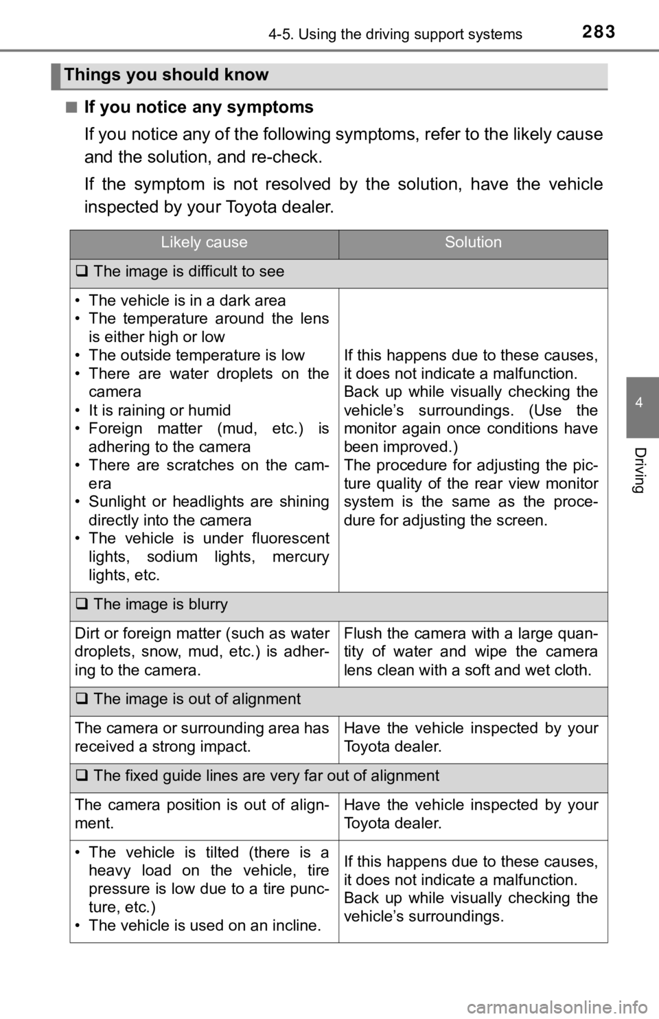
■If you notice any symptoms
If you notice any of the following symptoms, refer to the likel y cause
and the solution, and re-check.
If the symptom is not resolved by the solution, have the vehicl e
inspected by your Toyota dealer.
Things you should know
Likely causeSolution
The image is difficult to see
• The vehicle is in a dark area
• The temperature around the lens
is either high or low
• The outside temperature is low
• There are water droplets on the camera
• It is raining or humid
• Foreign matter (mud, etc.) is adhering to the camera
• There are scratches on the cam- era
• Sunlight or headlights are shining
directly into the camera
• The vehicle is under fluorescent lights, sodium lights, mercury
lights, etc.
If this happens due to these causes,
it does not indicate a malfunction.
Back up while visually checking the
vehicle’s surroundings. (Use the
monitor again once conditions have
been improved.)
The procedure for adjusting the pic-
ture quality of the rear view monitor
system is the same as the proce-
dure for adjusting the screen.
The image is blurry
Dirt or foreign matter (such as water
droplets, snow, mud, etc.) is adher-
ing to the camera.Flush the camera with a large quan-
tity of water and wipe the camera
lens clean with a soft and wet cloth.
The image is out of alignment
The camera or surrounding area has
received a strong impact.Have the vehicle inspected by your
Toyota dealer.
The fixed guide lines are very far out of alignment
The camera position is out of align-
ment.Have the vehicle inspected by your
Toyota dealer.
• The vehicle is tilted (there is a
heavy load on the vehicle, tire
pressure is low due to a tire punc-
ture, etc.)
• The vehicle is used on an incline.If this happens due to these causes,
it does not indicate a malfunction.
Back up while visually checking the
vehicle’s surroundings.
Page 307 of 672

3074-5. Using the driving support systems
4
Driving
WARNING
■When the TRAC/VSC/Trailer Sway Control are activated
The slip indicator light flashes. Always drive carefully. Reckless driving may
cause an accident. Exercise particular care when the indicator light flashes.
■ When the TRAC/VSC/Trailer Sway Control systems are turned off
Be especially careful and drive at a speed appropriate to the r oad condi-
tions. As these are the systems to help ensure vehicle stabilit y and driving
force, do not turn the TRAC/VSC/Trailer Sway Control systems of f unless
necessary.
Trailer Sway Control is part of the VSC system and will not operate if VSC is
turned off or experiences a malfunction.
■ Replacing tires
Make sure that all tires are of the specified size, brand, trea d pattern and
total load capacity. In addition, make sure that the tires are inflated to the
recommended tire inflation pressure level.
The ABS, TRAC, VSC and Trailer Sway Control systems will not function
correctly if different tires are installed on the vehicle.
Contact your Toyota dealer for further information when replaci ng tires or
wheels.
■ Handling of tires and the suspension
Using tires with any kind of problem or modifying the suspensio n will affect
the driving assist systems, and may cause a system to malfuncti on.
■ Trailer Sway Control precaution
The Trailer Sway Control system is not able to reduce trailer sway in all situ-
ations. Depending on many factors such as the conditions of the vehicle,
trailer, road surface, and driving environment, the Trailer Swa y Control sys-
tem may not be effective. Refer to your trailer owner’s manual for informa-
tion on how to tow your trailer properly.
■ If trailer sway occurs
Observe the following precautions.
Failure to do so may cause death or serious injury.
● Firmly grip the steering wheel. Steer straight ahead.
Do not try to control trailer swaying by turning the steering w heel.
● Begin releasing the accelerator pedal immediately but very grad ually to
reduce speed.
Do not increase speed. Do not apply vehicle brakes.
If you make no extreme correction with the steering or brakes, your vehicle
and trailer should stabilize. ( P. 191)