tow TOYOTA TUNDRA 2020 Owners Manual (in English)
[x] Cancel search | Manufacturer: TOYOTA, Model Year: 2020, Model line: TUNDRA, Model: TOYOTA TUNDRA 2020Pages: 608, PDF Size: 13.19 MB
Page 3 of 608

3
1
9 8
7 5 4
3
2
6
4-1. Before drivingDriving the vehicle ............. 184
Cargo and luggage............ 192
Vehicle load limits ............. 195
Trailer towing..................... 197
Dinghy towing.................... 216
4-2. Driving procedures Engine (ignition) switch (vehicles without
a smart key system) ........ 217
Engine (ignition) switch (vehicles with a smart
key system) ..................... 219
Automatic transmission ..... 225
Turn signal lever................ 232
Parking brake .................... 233
4-3. Operating the lights and wipers
Headlight switch ................ 234
Automatic High Beam ....... 239
Fog light switch ................. 244
Windshield wipers and washer ............................ 245
4-4. Refueling Opening the fuel tank cap .................................. 248 4-5. Using the driving support
systems
Toyota Safety Sense P ...... 252
PCS (Pre-Collision System) ........................... 259
LDA (Lane Departure Alert) ................................ 272
Dynamic radar cruise control.............................. 280
Cruise control .................... 294
Intuitive parking assist ....... 298
BSM (Blind Spot Monitor)......... 305
Four-wheel drive system ... 315
AUTO LSD system ............ 318
Driving assist systems ....... 320
Trailer brake controller....... 327
4-6. Driving tips Winter driving tips .............. 331
Off-road precautions .......... 335
4Driving
Page 5 of 608
5
1
9 8
7 5 4
3
2
6
6-1. Maintenance and careCleaning and protecting the vehicle exterior .......... 400
Cleaning and protecting the vehicle interior ........... 403
6-2. Maintenance Maintenance requirements ................... 406
General maintenance ........ 408
Emission inspection and maintenance (I/M)
programs ......................... 411
6-3. Do-it-yourself maintenance Do-it-yourself service precautions ..................... 412
Hood.................................. 414
Engine compartment ......... 415
Tires .................................. 426
Tire inflation pressure........ 440
Wheels .............................. 443
Air conditioning filter .......... 446
Wireless remote control/ electronic key battery ...... 449
Checking and replacing fuses ............................... 452
Light bulbs ......................... 455 7-1. Essential information
Emergency flashers ........... 472
If your vehicle has to be stopped in
an emergency.................. 473
If the vehicle is trapped in rising water .................. 475
7-2. Steps to take in an emergency
If your vehicle needs to be towed .......................... 476
If you think something is wrong............................... 481
Fuel pump shut off system ............................. 482
If a warning light turns on or a warning buzzer
sounds ............................. 483
If a warning message is displayed ......................... 491
If you have a flat tire .......... 504
If the engine will not start ................................. 519
If the electronic key does not operate properly
(vehicles with a smart
key system) .................... 521
If the vehicle battery is discharged ....................... 523
If your vehicle overheats.... 527
If the vehicle becomes stuck ................................ 530
6Maintenance and care7When trouble arises
Page 18 of 608
18Pictorial index
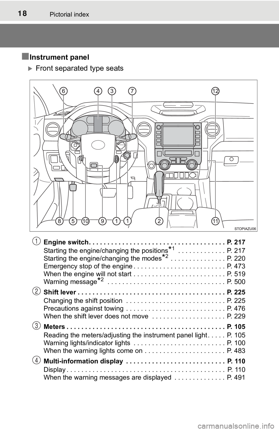
■Instrument panel
Front separated type seats
Engine switch . . . . . . . . . . . . . . . . . . . . . . . . . . . . . . . . . . . . . P. 217
Starting the engine/changing the positions
*1 . . . . . . . . . . . . . P. 217
Starting the engine/changing the modes
*2 . . . . . . . . . . . . . . . P. 220
Emergency stop of the engine . . . . . . . . . . . . . . . . . . . . . . . . . P. 473
When the engine will not start . . . . . . . . . . . . . . . . . . . . . . . . . P. 519
Warning message
*2 . . . . . . . . . . . . . . . . . . . . . . . . . . . . . . . . P. 500
Shift lever . . . . . . . . . . . . . . . . . . . . . . . . . . . . . . . . . . . . . . . . P. 225
Changing the shift position . . . . . . . . . . . . . . . . . . . . . . . . . . . P. 225
Precautions against towing . . . . . . . . . . . . . . . . . . . . . . . . . . . P. 476
When the shift lever does not move . . . . . . . . . . . . . . . . . . . . P. 229
Meters . . . . . . . . . . . . . . . . . . . . . . . . . . . . . . . . . . . . . . . . . . . P. 105
Reading the meters/adjusting the instrument panel light . . . . . P. 105
Warning lights/indicator lights . . . . . . . . . . . . . . . . . . . . . . . . . P. 100
When the warning lights come on . . . . . . . . . . . . . . . . . . . . . . P. 483
Multi-information display . . . . . . . . . . . . . . . . . . . . . . . . . . . P. 110
Display . . . . . . . . . . . . . . . . . . . . . . . . . . . . . . . . . . . . . . . . . . . P. 110
When the warning messages are displayed . . . . . . . . . . . . . . P. 491
1
2
3
4
Page 20 of 608
20Pictorial index
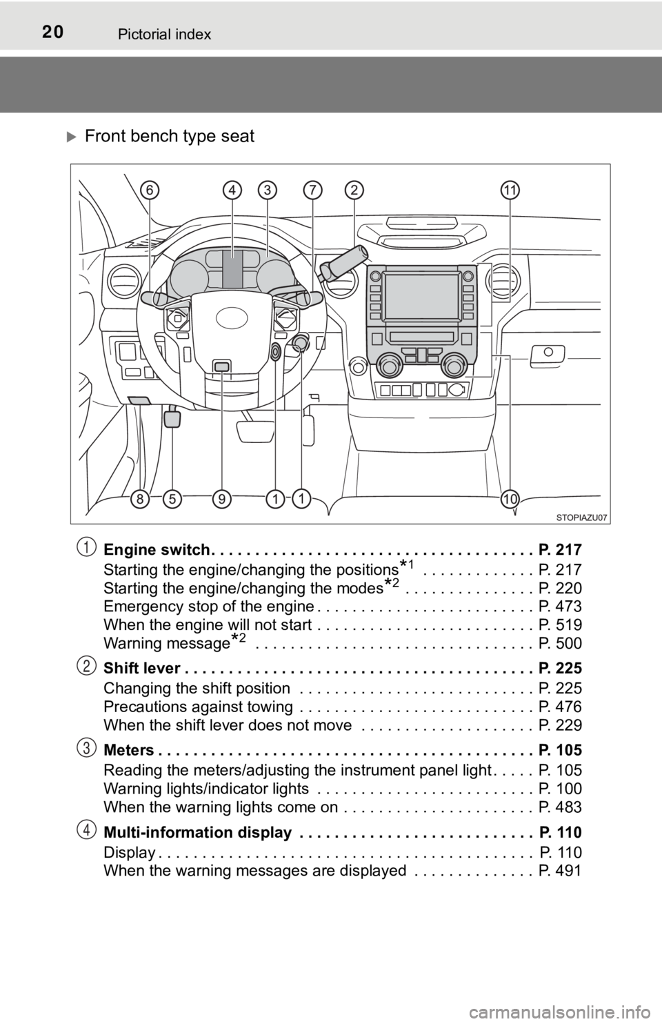
Front bench type seat
Engine switch . . . . . . . . . . . . . . . . . . . . . . . . . . . . . . . . . . . . . P. 217
Starting the engine/changing the positions
*1 . . . . . . . . . . . . . P. 217
Starting the engine/changing the modes
*2 . . . . . . . . . . . . . . . P. 220
Emergency stop of the engine . . . . . . . . . . . . . . . . . . . . . . . . . P. 473
When the engine will not start . . . . . . . . . . . . . . . . . . . . . . . . . P. 519
Warning message
*2 . . . . . . . . . . . . . . . . . . . . . . . . . . . . . . . . P. 500
Shift lever . . . . . . . . . . . . . . . . . . . . . . . . . . . . . . . . . . . . . . . . P. 225
Changing the shift position . . . . . . . . . . . . . . . . . . . . . . . . . . . P. 225
Precautions against towing . . . . . . . . . . . . . . . . . . . . . . . . . . . P. 476
When the shift lever does not move . . . . . . . . . . . . . . . . . . . . P. 229
Meters . . . . . . . . . . . . . . . . . . . . . . . . . . . . . . . . . . . . . . . . . . . P. 105
Reading the meters/adjusting the instrument panel light . . . . . P. 105
Warning lights/indicator lights . . . . . . . . . . . . . . . . . . . . . . . . . P. 100
When the warning lights come on . . . . . . . . . . . . . . . . . . . . . . P. 483
Multi-information display . . . . . . . . . . . . . . . . . . . . . . . . . . . P. 110
Display . . . . . . . . . . . . . . . . . . . . . . . . . . . . . . . . . . . . . . . . . . . P. 110
When the warning messages are displayed . . . . . . . . . . . . . . P. 491
1
2
3
4
Page 22 of 608
22Pictorial index
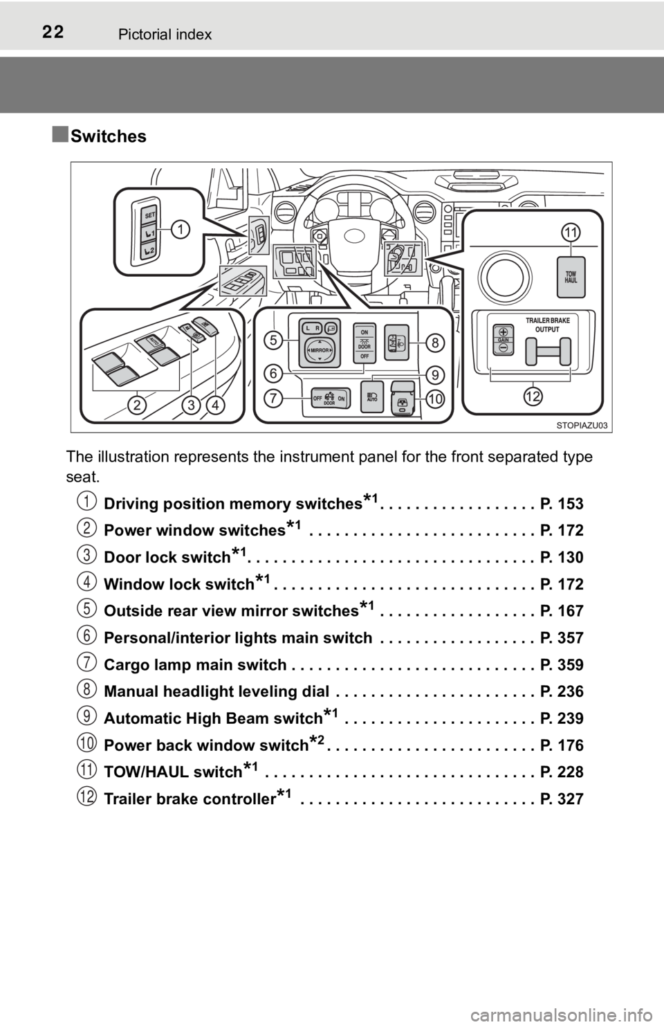
■Switches
The illustration represents the instrument panel for the front separated type
seat.Driving position memory switches
*1. . . . . . . . . . . . . . . . . . P. 153
Power window switches
*1 . . . . . . . . . . . . . . . . . . . . . . . . . . P. 172
Door lock switch
*1. . . . . . . . . . . . . . . . . . . . . . . . . . . . . . . . . P. 130
Window lock switch
*1. . . . . . . . . . . . . . . . . . . . . . . . . . . . . . P. 172
Outside rear view mirror switches
*1 . . . . . . . . . . . . . . . . . . P. 167
Personal/interior lights main switch . . . . . . . . . . . . . . . . . . P. 357
Cargo lamp main switch . . . . . . . . . . . . . . . . . . . . . . . . . . . . P. 359
Manual headlight leveling dial . . . . . . . . . . . . . . . . . . . . . . . P. 236
Automatic High Beam switch
*1 . . . . . . . . . . . . . . . . . . . . . . P. 239
Power back window switch
*2. . . . . . . . . . . . . . . . . . . . . . . . P. 176
TOW/HAUL switch
*1 . . . . . . . . . . . . . . . . . . . . . . . . . . . . . . . P. 228
Trailer brake controller
*1 . . . . . . . . . . . . . . . . . . . . . . . . . . . P. 327
1
2
3
4
5
6
7
8
9
10
11
12
Page 44 of 608
441-1. For safe use
WARNING
■SRS airbag precautions
Observe the following precautions regarding the SRS airbags.
Failure to do so may cause death or serious injury.
● The driver and all passengers in the vehicle must wear their se at belts
properly.
The SRS airbags are supplemental devices to be used with the se at belts.
● The SRS driver airbag deploys with considerable force, and can cause
death or serious injury especially if the driver is very close to the airbag.
The National Highway Traffic Safety Administration (NHTSA) advi ses:
Since the risk zone for the driver’s airbag is the first 2 - 3 in. (50 - 75 mm)
of inflation, placing yourself 10 in. (250 mm) from your driver airbag pro-
vides you with a clear margin of safety. This distance is measured from
the center of the steering wheel to your breastbone. If you sit less than
10 in. (250 mm) away now, you can change your driving position i n sev-
eral ways:
• Move your seat to the rear as far as you can while still reach ing the ped-
als comfortably.
• Slightly recline the back of the seat. Although vehicle designs vary, many drivers can achieve the 10 in.
(250 mm) distance, even with the driver seat all the way forward , simply
by reclining the back of the seat somewhat. If reclining the ba ck of your
seat makes it hard to see the road, raise yourself by using a f irm, non-
slippery cushion, or raise the seat if your vehicle has that feature.
• If your steering wheel is adjustable, tilt it downward. This points the air- bag toward your chest instead of your head and neck.
The seat should be adjusted as recommended by NHTSA above, whil e
still maintaining control of the foot pedals, steering wheel, and your view
of the instrument panel controls.
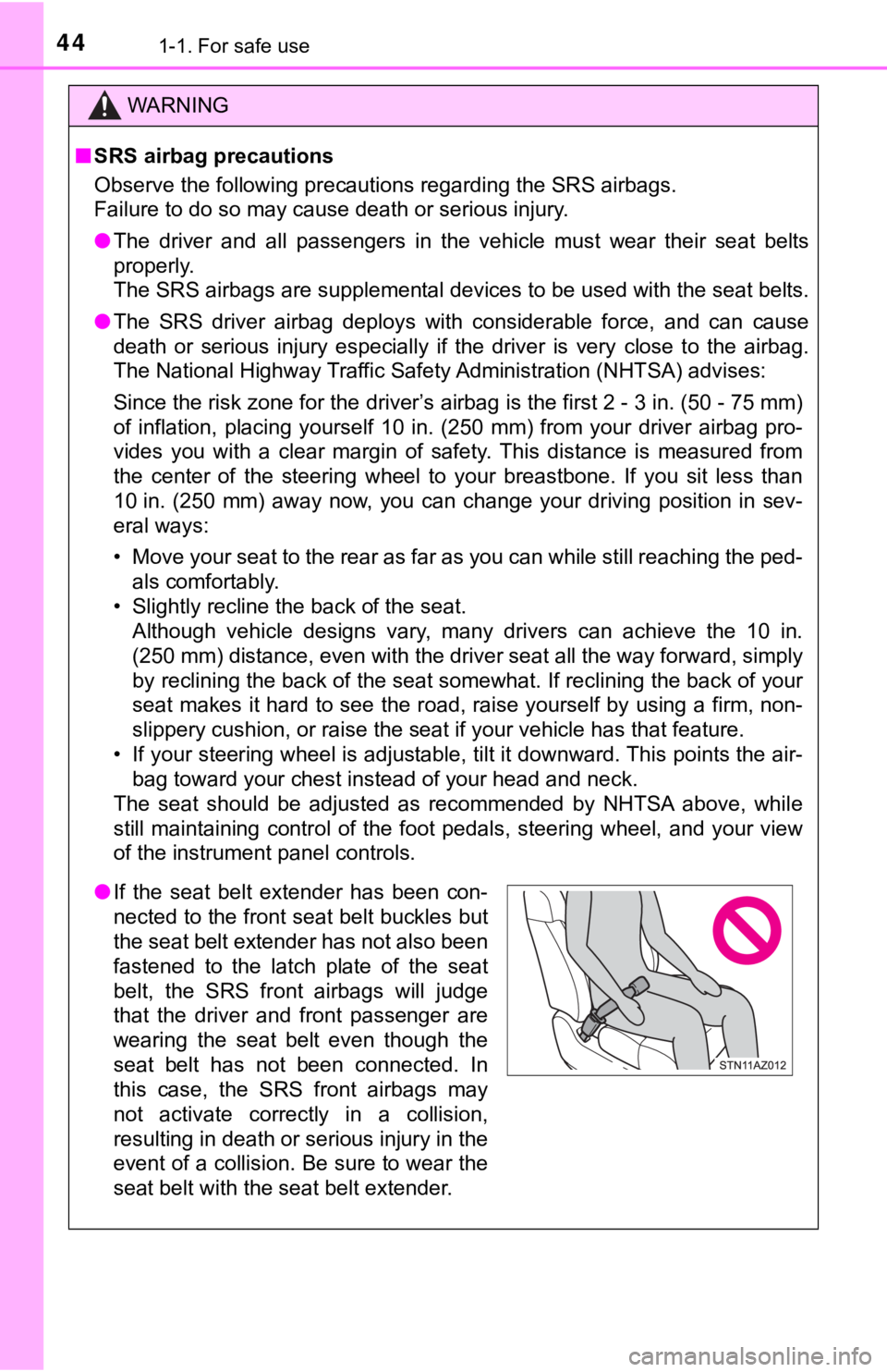
● If the seat belt extender has been con-
nected to the front seat belt buckles but
the seat belt extender has not also been
fastened to the latch plate of the seat
belt, the SRS front airbags will judge
that the driver and front passenger are
wearing the seat belt even though the
seat belt has not been connected. In
this case, the SRS front airbags may
not activate correctly in a collision,
resulting in death or serious injury in the
event of a collision. Be sure to wear the
seat belt with the seat belt extender.
Page 46 of 608
461-1. For safe use
WARNING
■SRS airbag precautions
● Do not hang coat hangers or other hard objects on the coat hook s. All of
these items could become projectiles and may cause death or ser ious
injury, should the SRS curtain shield airbags deploy.
● If a vinyl cover is put on the area where the SRS knee airbag w ill deploy,
be sure to remove it.
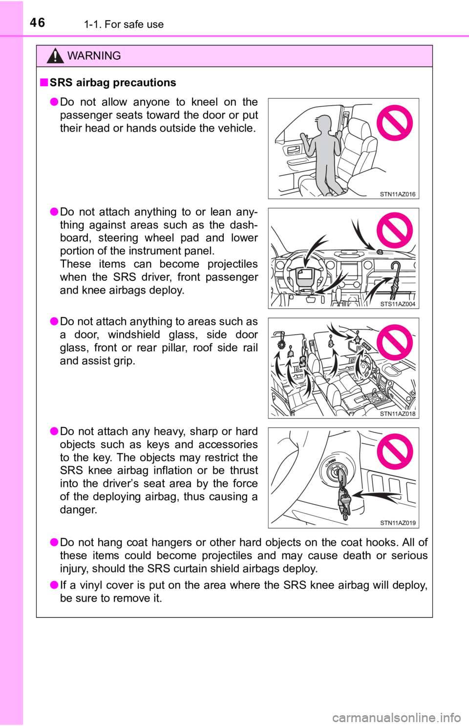
● Do not allow anyone to kneel on the
passenger seats toward the door or put
their head or hands outside the vehicle.
● Do not attach anything to or lean any-
thing against areas such as the dash-
board, steering wheel pad and lower
portion of the instrument panel.
These items can become projectiles
when the SRS driver, front passenger
and knee airbags deploy.
● Do not attach anything to areas such as
a door, windshield glass, side door
glass, front or rear pillar, roof side rail
and assist grip.
● Do not attach any heavy, sharp or hard
objects such as keys and accessories
to the key. The objects may restrict the
SRS knee airbag inflation or be thrust
into the driver’s seat area by the force
of the deploying airbag, thus causing a
danger.
Page 83 of 608
831-2. Emergency assistance
1
For safety and security
■Enhanced Roadside Assistance
Enhanced Roadside Assistance adds GPS data to the already
included warranty-based Toyota roadside service.
Subscribers can press the “SOS” button to reach a Safety Connec t
response-center agent, who can he lp with a wide range of needs,
such as: towing, flat tire, fuel delivery, etc. For a description of the
Enhanced Roadside Assistance se rvices and their limitations,
please see the Safety Connect Te rms and Conditions, which are
available at Toyota.com in the United States, Toyotapr.com in
Puerto Rico and Toyota.ca in Canada.
Important! Read this informatio n before using Safety Connect.
■Exposure to radio frequency signals
The Safety Connect system installed in your vehicle is a low-po wer
radio transmitter and receiver. I t receives and also sends out radio
frequency (RF) signals.
In August 1996, the Federal Communications Commission (FCC)
adopted RF exposure guidelines with safety levels for mobile wi re-
less phones. Those guidelines are consistent with the safety stan-
dards previously set by the following U.S. and international
standards bodies.
● ANSI (American National Stand ards Institute) C95.1 [1992]
● NCRP (National Council on Radi ation Protection and Measure-
ment) Report 86 [1986]
● ICNIRP (International Commission on Non-Ionizing Radiation
Protection) [1996]
Those standards were based on comprehensive and periodic eval-
uations of the relevant scienti fic literature. Over 120 scientists, engi-
neers, and physicians from unive rsities, and government health
agencies and industries reviewed the available body of research to
develop the ANSI Standard (C95.1).
The design of Safety Connect complies with the FCC guidelines i n
addition to those standards.
Safety information for Safety Connect
Page 103 of 608
1032. Instrument cluster
2
Instrument cluster
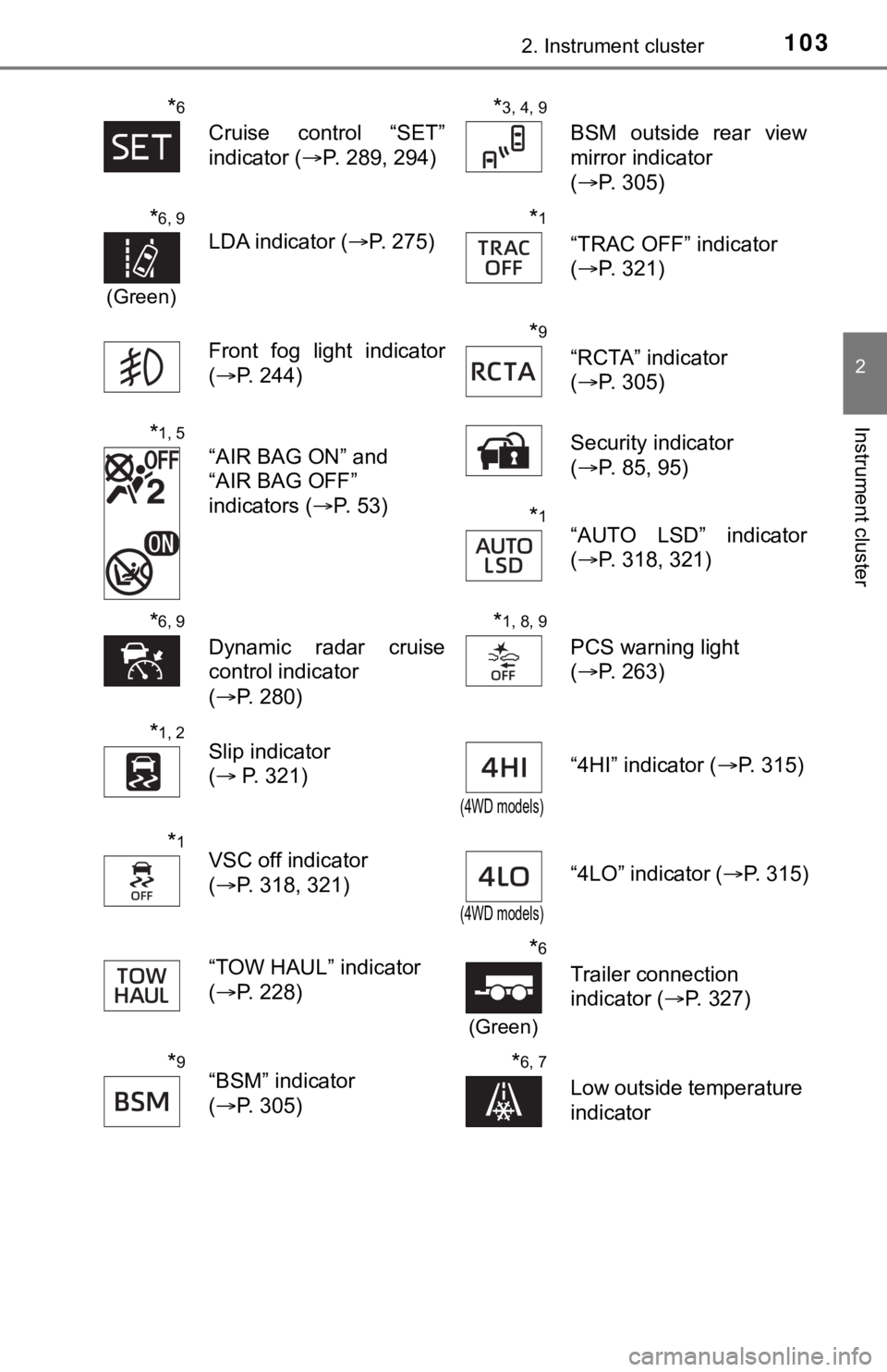
*6
Cruise control “SET”
indicator (P. 289, 294)
*3, 4, 9
BSM outside rear view
mirror indicator
(P. 305)
*6, 9
(Green)
LDA indicator ( P. 275)
*1
“TRAC OFF” indicator
(P. 321)
Front fog light indicator
( P. 244)
*9
“RCTA” indicator
(P. 305)
*1, 5
“AIR BAG ON” and
“AIR BAG OFF”
indicators ( P. 53) Security indicator
(
P. 85, 95)
*1“AUTO LSD” indicator
(P. 318, 321)
*6, 9
Dynamic radar cruise
control indicator
(P. 280)
*1, 8, 9
PCS warning light
(P. 263)
*1, 2Slip indicator
( P. 321)
(4WD models)
“4HI” indicator ( P. 315)
*1VSC off indicator
(P. 318, 321)
(4WD models)
“4LO” indicator ( P. 315)
“TOW HAUL” indicator
( P. 228)
*6
(Green)
Trailer connection
indicator ( P. 327)
*9“BSM” indicator
(P. 305)*6, 7
Low outside temperature
indicator
Page 123 of 608

1233-1. Key information
3
Operation of each component
■If you lose your keys
Type A and B
New genuine key can be made by your Toyota dealer using the other key and
the key number stamped on your key number plate.
Keep the plate in a safe place such as your wallet, not in the vehicle.
Type C
New genuine key can be made by your Toyota dealer.
The following are necessary when making new keys.
Mechanical key:
The key number for the mechanical key stamped on the number pla te and the
other key.
Key:
The key number for key stamped on the key number plate.
Keep the plates in a safe place such as your wallet, not in the vehicle.
There are key number plates for the mechanical key and key resp ectively.
When storing them, keep them in a safe place in a manner to dis tinguish one
from the other (such as markings, etc.).
■ When riding in an aircraft (type B or type C)
When bringing an wireless remote control function onto an aircr aft, make sure
you do not press any button on the key while inside the aircraf t cabin. If you
are carrying the key in your bag, etc., ensure that the buttons are not likely to
be pressed accidentally. Pressing a button may cause the key to emit radio
waves that could interfere with the operation of the aircraft.
■ Conditions affecting operation (type B or type C)
Type B
The wireless remote control function may not operate normally i n the following
situations.
● Near a TV tower, radio station, electric power plant, airport o r other facility
that generates strong radio waves
● When carrying a portable radio, cellular phone or other wireles s communi-
cation device
● When multiple wireless keys are in the vicinity
● When the wireless key has come into contact with, or is covered by a metal-
lic object
● When a wireless key (that emits radio waves) is being used near by
● When the wireless key has been left near an electrical applianc e such as a
personal computer
Type C
P. 142