coolant temperature TOYOTA YARIS CROSS 2022 Owners Manual
[x] Cancel search | Manufacturer: TOYOTA, Model Year: 2022, Model line: YARIS CROSS, Model: TOYOTA YARIS CROSS 2022Pages: 618, PDF Size: 130.77 MB
Page 83 of 618
81
2
CV Owner's Manual_Europe_M52N20_en
2-1. Instrument cluster
Vehicle status information and indicators
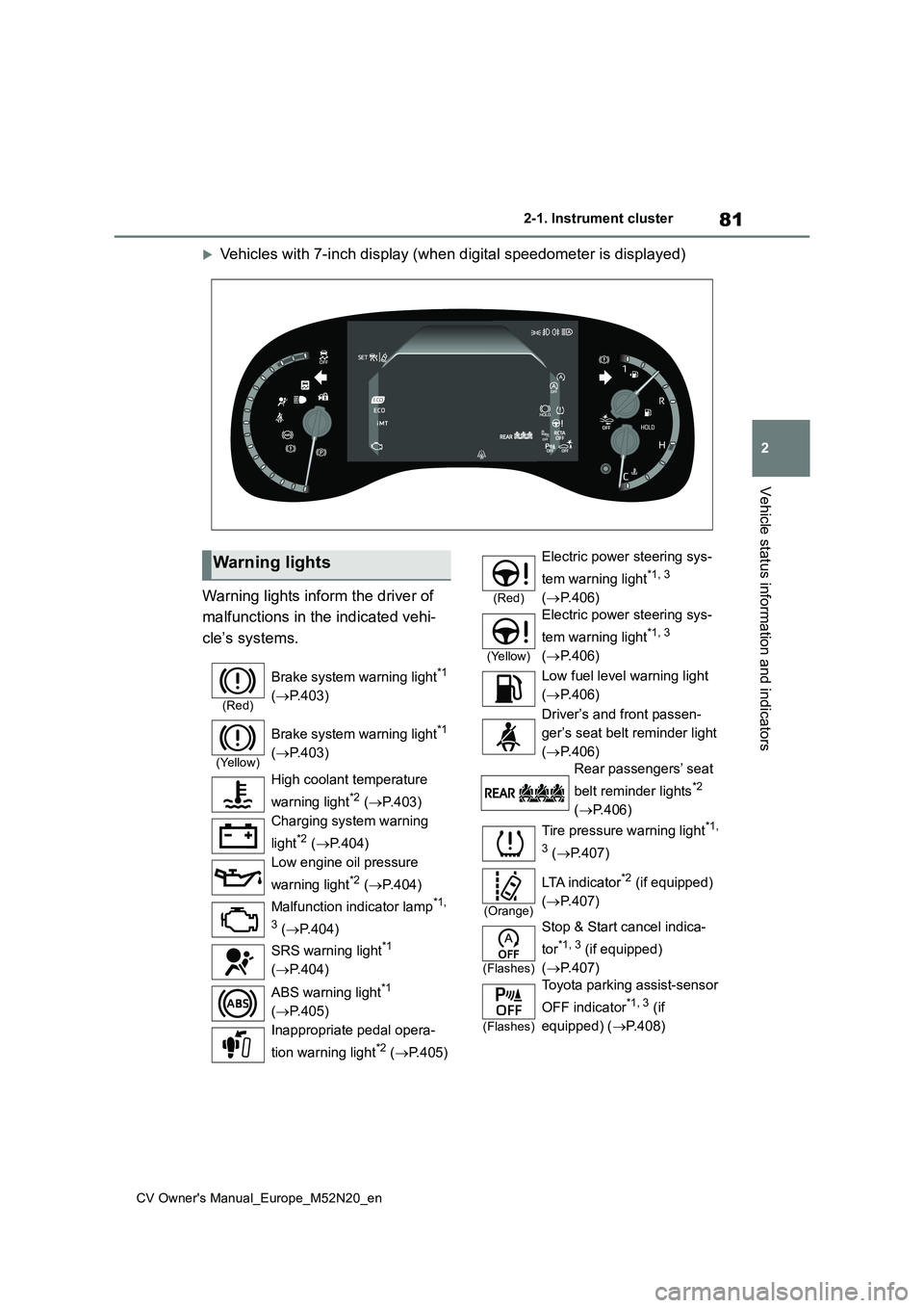
Vehicles with 7-inch display (when digital speedometer is displayed)
Warning lights inform the driver of
malfunctions in the indicated vehi-
cle’s systems.
Warning lights
(Red)
Brake system warning light*1
( P.403)
(Yellow)
Brake system warning light*1
( P.403)
High coolant temperature
warning light*2 ( P.403)
Charging system warning
light*2 ( P.404)
Low engine oil pressure
warning light*2 ( P.404)
Malfunction indicator lamp*1,
3 ( P.404)
SRS warning light*1
( P.404)
ABS warning light*1
( P.405)
Inappropriate pedal opera-
tion warning light*2 ( P.405)
(Red)
Electric power steering sys-
tem warning light*1, 3
( P.406)
(Yellow)
Electric power steering sys-
tem warning light*1, 3
( P.406)
Low fuel level warning light
( P.406)
Driver’s and front passen-
ger’s seat belt reminder light
( P.406)
Rear passengers’ seat
belt reminder lights*2
( P.406)
Tire pressure warning light*1,
3 ( P.407)
(Orange)
LTA i n d i c a t o r*2 (if equipped)
( P.407)
(Flashes)
Stop & Start cancel indica-
tor*1, 3 (if equipped)
( P.407)
(Flashes)
Toyota parking assist-sensor
OFF indicator*1, 3 (if
equipped) ( P.408)
Page 87 of 618
85
2
CV Owner's Manual_Europe_M52N20_en
2-1. Instrument cluster
Vehicle status information and indicators
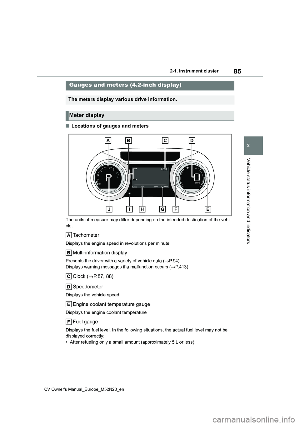
■Locations of gauges and meters
The units of measure may differ depending on the intended destination of the vehi-
cle.
Tachometer
Displays the engine speed in revolutions per minute
Multi-information display
Presents the driver with a variety of vehicle data ( P. 9 4 )
Displays warning messages if a malfunction occurs ( P.413)
Clock (P.87, 88)
Speedometer
Displays the vehicle speed
Engine coolant temperature gauge
Displays the engine coolant temperature
Fuel gauge
Displays the fuel level. In the following situations, the actua l fuel level may not be
displayed correctly:
• After refueling only a small amount (approximately 5 L or less )
Gauges and meters (4.2-inch display)
The meters display various drive information.
Meter display
Page 89 of 618
87
2
CV Owner's Manual_Europe_M52N20_en
2-1. Instrument cluster
Vehicle status information and indicators
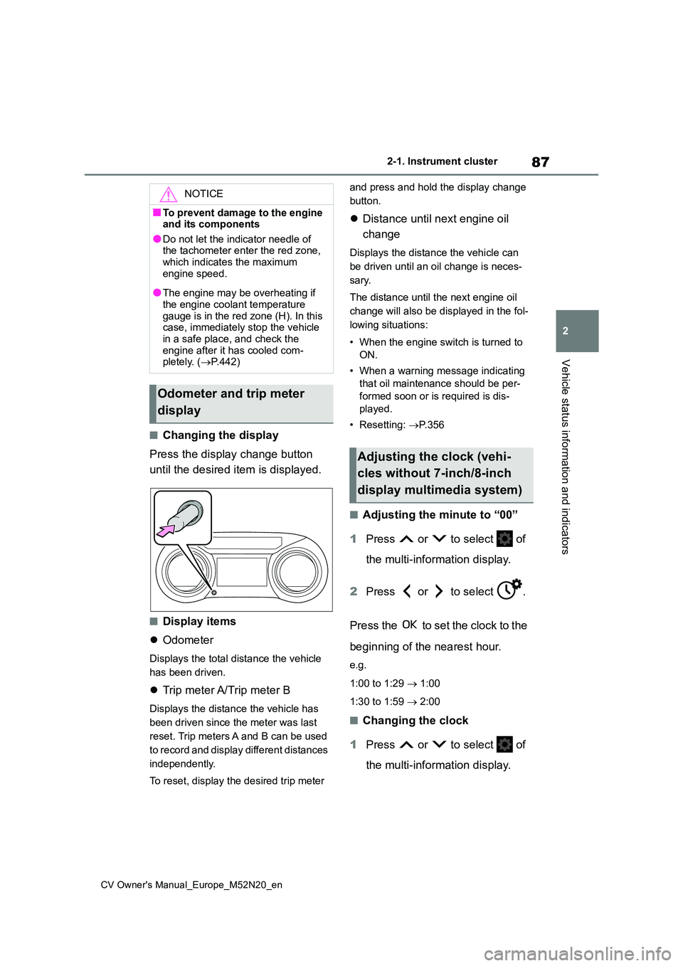
■Changing the display
Press the display change button
until the desired item is displayed.
■Display items
Odometer
Displays the total distance the vehicle
has been driven.
Trip meter A/Trip meter B
Displays the distance the vehicle has
been driven since the meter was last
reset. Trip meters A and B can be used
to record and display different distances
independently.
To reset, display the desired trip meter
and press and hold the display change
button.
Distance until next engine oil
change
Displays the distance the vehicle can
be driven until an oil change is neces-
sary.
The distance until the next engine oil
change will also be displayed in the fol-
lowing situations:
• When the engine switch is turned to
ON.
• When a warning message indicating
that oil maintenance should be per-
formed soon or is required is dis-
played.
• Resetting: P. 3 5 6
■Adjusting the minute to “00”
1 Press or to select of
the multi-information display.
2 Press or to select .
Press the to set the clock to the
beginning of the nearest hour.
e.g.
1:00 to 1:29 1:00
1:30 to 1:59 2:00
■Changing the clock
1 Press or to select of
the multi-information display.
NOTICE
■To prevent damage to the engine and its components
●Do not let the indicator needle of the tachometer enter the red zone, which indicates the maximum
engine speed.
●The engine may be overheating if
the engine coolant temperature gauge is in the red zone (H). In this case, immediately stop the vehicle
in a safe place, and check the engine after it has cooled com-pletely. ( P.442)
Odometer and trip meter
display
Adjusting the clock (vehi-
cles without 7-inch/8-inch
display multimedia system)
Page 91 of 618
89
2
CV Owner's Manual_Europe_M52N20_en
2-1. Instrument cluster
Vehicle status information and indicators
The display of the speedometer can be selected from two types, analog or
digital. ( P.104)
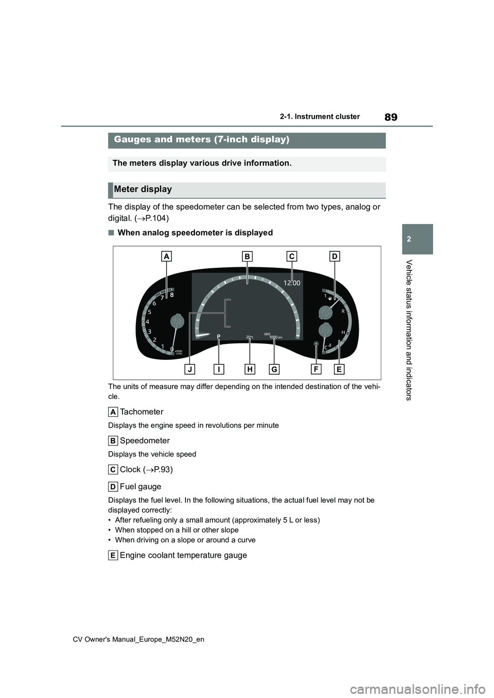
■When analog speedometer is displayed
The units of measure may differ depending on the intended destination of the vehi-
cle.
Tachometer
Displays the engine speed in revolutions per minute
Speedometer
Displays the vehicle speed
Clock ( P.93)
Fuel gauge
Displays the fuel level. In the following situations, the actua l fuel level may not be
displayed correctly:
• After refueling only a small amount (approximately 5 L or less )
• When stopped on a hill or other slope
• When driving on a slope or around a curve
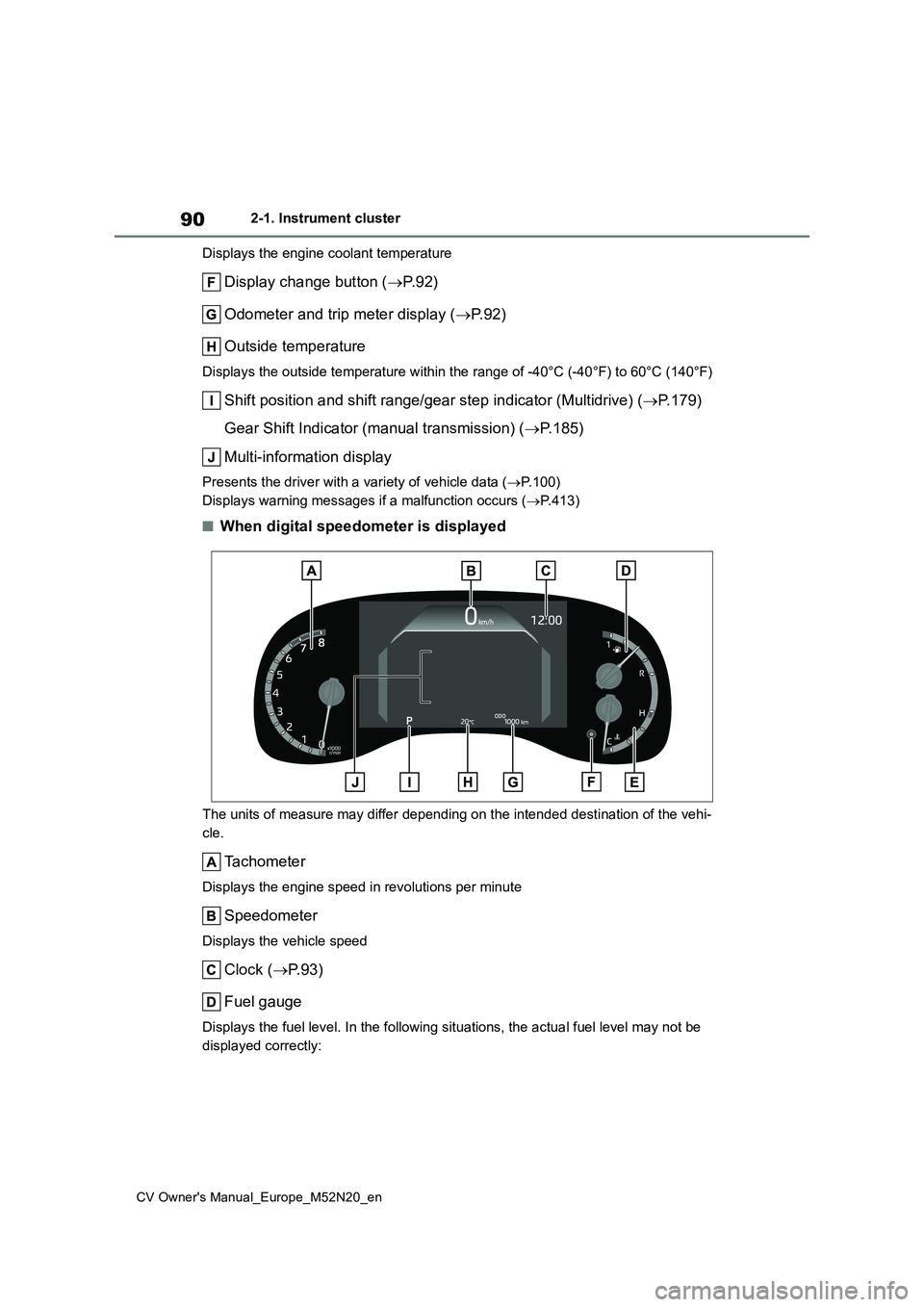
Engine coolant temperature gauge
Gauges and meters (7-inch display)
The meters display various drive information.
Meter display
Page 92 of 618
90
CV Owner's Manual_Europe_M52N20_en
2-1. Instrument cluster
Displays the engine coolant temperature
Display change button ( P. 9 2 )
Odometer and trip meter display ( P. 9 2 )
Outside temperature
Displays the outside temperature within the range of -40°C (-40 °F) to 60°C (140°F)
Shift position and shift range/gear step indicator (Multidrive) (P.179)
Gear Shift Indicator (manual transmission) ( P.185)
Multi-information display
Presents the driver with a variety of vehicle data ( P.100)
Displays warning messages if a malfunction occurs ( P.413)
■When digital speedometer is displayed
The units of measure may differ depending on the intended destination of the vehi-
cle.
Tachometer
Displays the engine speed in revolutions per minute
Speedometer
Displays the vehicle speed
Clock ( P.93)
Fuel gauge
Displays the fuel level. In the following situations, the actua l fuel level may not be
displayed correctly:
Page 93 of 618
91
2
CV Owner's Manual_Europe_M52N20_en
2-1. Instrument cluster
Vehicle status information and indicators
• After refueling only a small amount (approximately 5 L or less)
• When stopped on a hill or other slope
• When driving on a slope or around a curve
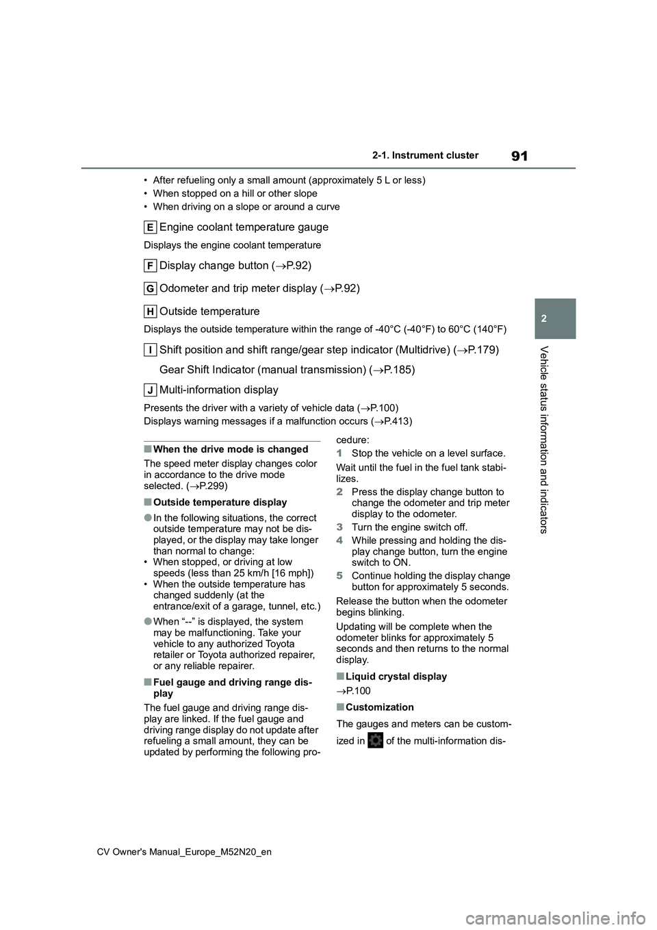
Engine coolant temperature gauge
Displays the engine coolant temperature
Display change button ( P. 9 2 )
Odometer and trip meter display ( P. 9 2 )
Outside temperature
Displays the outside temperature within the range of -40°C (-40 °F) to 60°C (140°F)
Shift position and shift range/gear step indicator (Multidrive) (P.179)
Gear Shift Indicator (manual transmission) ( P.185)
Multi-information display
Presents the driver with a variety of vehicle data ( P.100)
Displays warning messages if a malfunction occurs ( P.413)
■When the drive mode is changed
The speed meter display changes color
in accordance to the drive mode selected. ( P.299)
■Outside temperature display
●In the following situations, the correct outside temperature may not be dis-played, or the display may take longer
than normal to change: • When stopped, or driving at low speeds (less than 25 km/h [16 mph])
• When the outside temperature has changed suddenly (at the entrance/exit of a garage, tunnel, etc.)
●When “--” is displayed, the system may be malfunctioning. Take your
vehicle to any authorized Toyota retailer or Toyota authorized repairer, or any reliable repairer.
■Fuel gauge and driving range dis-
play
The fuel gauge and driving range dis-
play are linked. If the fuel gauge and driving range display do not update after refueling a small amount, they can be
updated by performing the following pro-
cedure:
1 Stop the vehicle on a level surface.
Wait until the fuel in the fuel tank stabi- lizes.
2 Press the display change button to change the odometer and trip meter
display to the odometer.
3 Turn the engine switch off.
4 While pressing and holding the dis- play change button, turn the engine switch to ON.
5 Continue holding the display change
button for approximately 5 seconds.
Release the button when the odometer begins blinking.
Updating will be complete when the odometer blinks for approximately 5 seconds and then returns to the normal
display.
■Liquid crystal display
P. 1 0 0
■Customization
The gauges and meters can be custom-
ized in of the multi-information dis-
Page 94 of 618
92
CV Owner's Manual_Europe_M52N20_en
2-1. Instrument cluster
play. ( P.457)
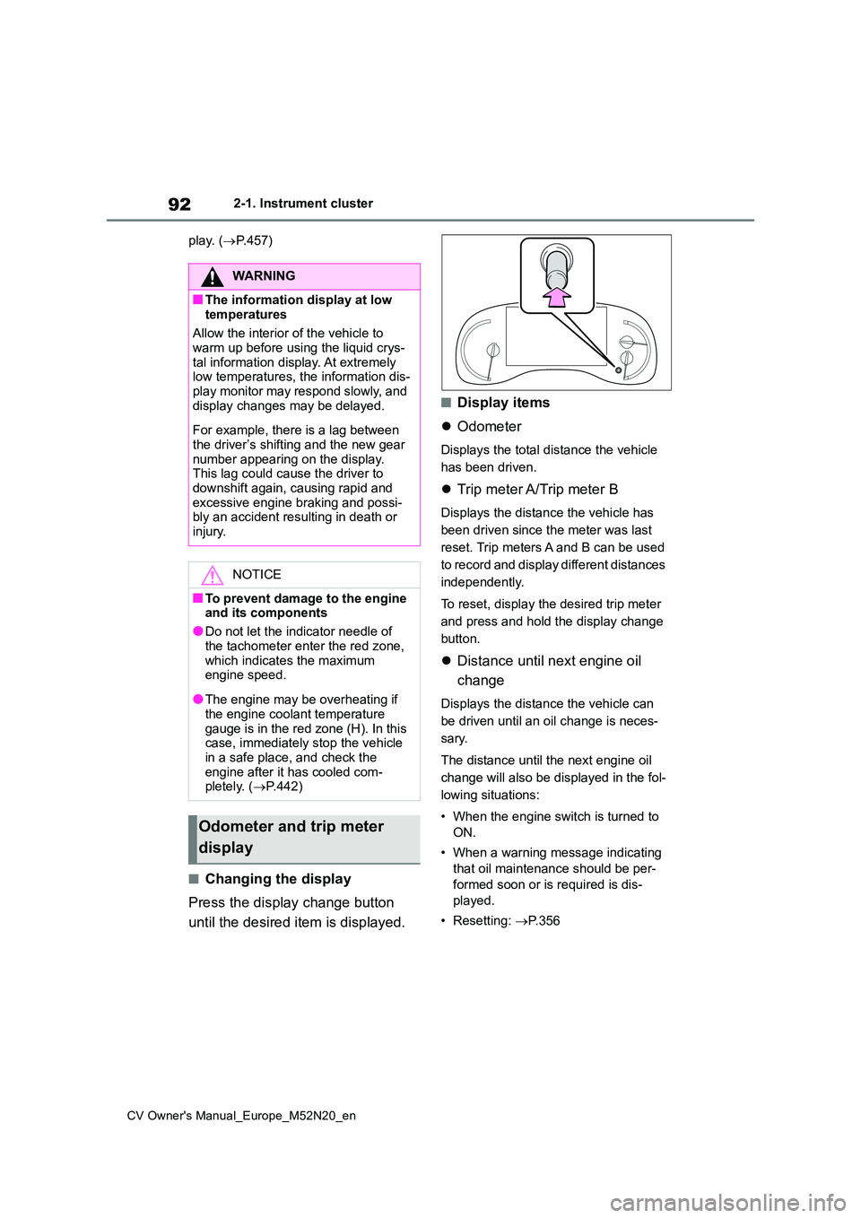
■Changing the display
Press the display change button
until the desired item is displayed.
■Display items
Odometer
Displays the total distance the vehicle
has been driven.
Trip meter A/Trip meter B
Displays the distance the vehicle has
been driven since the meter was last
reset. Trip meters A and B can be used
to record and display different distances
independently.
To reset, display the desired trip meter
and press and hold the display change
button.
Distance until next engine oil
change
Displays the distance the vehicle can
be driven until an oil change is neces-
sary.
The distance until the next engine oil
change will also be displayed in the fol-
lowing situations:
• When the engine switch is turned to
ON.
• When a warning message indicating
that oil maintenance should be per-
formed soon or is required is dis-
played.
• Resetting: P. 3 5 6
WARNING
■The information display at low
temperatures
Allow the interior of the vehicle to warm up before using the liquid crys-
tal information display. At extremely low temperatures, the information dis-play monitor may respond slowly, and
display changes may be delayed.
For example, there is a lag between
the driver’s shifting and the new gear number appearing on the display. This lag could cause the driver to
downshift again, causing rapid and excessive engine braking and possi-bly an accident resulting in death or
injury.
NOTICE
■To prevent damage to the engine and its components
●Do not let the indicator needle of
the tachometer enter the red zone, which indicates the maximum engine speed.
●The engine may be overheating if the engine coolant temperature
gauge is in the red zone (H). In this case, immediately stop the vehicle in a safe place, and check the
engine after it has cooled com- pletely. ( P.442)
Odometer and trip meter
display
Page 173 of 618
171
4
CV Owner's Manual_Europe_M52N20_en
4-1. Before driving
Driving
■Sudden acceleration/steering
input/cornering
Executing sharp turns when towing
may result in the trailer colliding
with your vehicle. Decelerate well in
advance when approaching turns
and take them slowly and carefully
to avoid sudden braking.
■Important points regarding
turning
The wheels of the trailer will travel
closer to the inside of the curve
than the wheels of the vehicle. To
make allowance for this, take the
turns wider than you would nor-
mally do.
■Important points regarding
stability
Vehicle movement resulting from
uneven road surfaces and strong
crosswinds will affect handling. The
vehicle may also be rocked by
passing buses or large trucks. Fre-
quently check behind when moving
alongside such vehicles. As soon
as such vehicle movement occurs,
immediately start to decelerate
smoothly by slowly applying the
brakes. Always steer the vehicle
straight ahead while braking.
■Passing other vehicles
Consider the total combined length
of your vehicle and trailer and
ensure that the vehicle-to-vehicle
distance is sufficient before execut-
ing lane changes.
■Transmission information
Multidrive
To maintain engine braking effi-
ciency and charging system perfor-
mance when using engine braking,
do not use the transmission in D,
must be in M and select gear step 4
or lower. ( P.179)
Manual transmission
Refrain from driving in 6th gear to
maintain the effectiveness of
engine braking and to maintain
charging system performance.
■If the engine overheats
Towing a loaded trailer up a long,
steep incline in temperatures
exceeding 30°C (85°F) may result
in the engine overheating. If the
engine coolant temperature gauge
indicates that the engine is over-
heating, turn the air conditioning off
immediately, leave the road and
stop the vehicle in a safe place.
( P.442)
■When parking the vehicle
Always place wheel chocks under
the wheels of both the vehicle and
trailer. Firmly set the parking brake
and shift the shift lever to P (Multid-
rive) and 1 or R (manual transmis-
sion).
WARNING
F o l l o w a l l t h e i n s t r u c t i o n s d e s c r i b e d i n
this section. Failure to do so could cause an accident resulting in death or serious injury.
Page 270 of 618
268
CV Owner's Manual_Europe_M52N20_en
4-5. Using the driving support systems
When the engine starts, the Stop &
Start indicator will turn off.
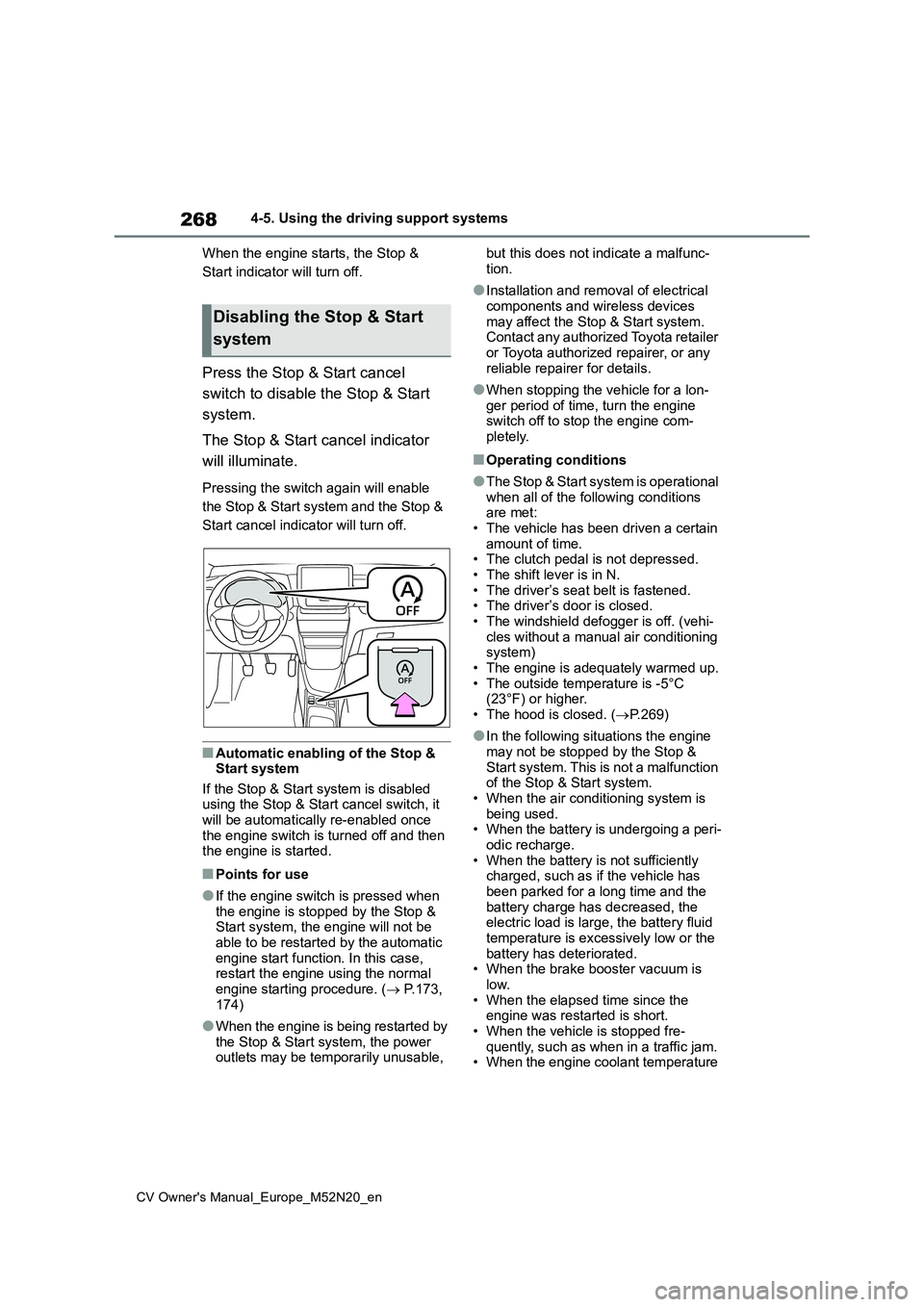
Press the Stop & Start cancel
switch to disable the Stop & Start
system.
The Stop & Start cancel indicator
will illuminate.
Pressing the switch again will enable
the Stop & Start system and the Stop &
Start cancel indicator will turn off.
■Automatic enabling of the Stop & Start system
If the Stop & Start system is disabled using the Stop & Start cancel switch, it will be automatically re-enabled once
the engine switch is turned off and then the engine is started.
■Points for use
●If the engine switch is pressed when the engine is stopped by the Stop & Start system, the engine will not be
able to be restarted by the automatic engine start function. In this case, restart the engine using the normal
engine starting procedure. ( P.173, 174)
●When the engine is being restarted by the Stop & Start system, the power outlets may be temporarily unusable,
but this does not indicate a malfunc-
tion.
●Installation and removal of electrical
components and wireless devices may affect the Stop & Start system. Contact any authorized Toyota retailer
or Toyota authorized repairer, or any reliable repairer for details.
●When stopping the vehicle for a lon-ger period of time, turn the engine switch off to stop the engine com-
pletely.
■Operating conditions
●The Stop & Start system is operational
when all of the following conditions are met:• The vehicle has been driven a certain
amount of time. • The clutch pedal is not depressed.• The shift lever is in N.
• The driver’s seat belt is fastened. • The driver’s door is closed.• The windshield defogger is off. (vehi-
cles without a manual air conditioning system)• The engine is adequately warmed up.
• The outside temperature is -5°C (23°F) or higher.• The hood is closed. ( P.269)
●In the following situations the engine may not be stopped by the Stop &
Start system. This is not a malfunction of the Stop & Start system.• When the air conditioning system is
being used. • When the battery is undergoing a peri-odic recharge.
• When the battery is not sufficiently charged, such as if the vehicle has been parked for a long time and the
battery charge has decreased, the electric load is large, the battery fluid temperature is excessively low or the
battery has deteriorated. • When the brake booster vacuum is low.
• When the elapsed time since the engine was restarted is short.• When the vehicle is stopped fre-
quently, such as when in a traffic jam. • When the engine coolant temperature
Disabling the Stop & Start
system
Page 351 of 618
349
6
CV Owner's Manual_Europe_M52N20_en
6-2. Maintenance
Maintenance and care
request that a record of maintenance
be kept.
■Does your vehicle need repairs?
Be on the alert for changes in perfor- mance and sounds, and visual tip-offs
that indicate service is needed. Some important clues are:
●Engine misses (misfire), stumbling or pinging
●Appreciable loss of power
●Strange engine noises
●A fluid leak under the vehicle (How-ever, water dripping from the air con-
ditioning system after use is normal.)
●Change in exhaust sound (This may
indicate a dangerous carbon monox- ide leak. Drive with the windows open and have the exhaust system checked
immediately.)
●Flat-looking tires, excessive tire
squeal when cornering, uneven tire wear
●Vehicle pulls to one side when driven straight on a level road
●Strange noises related to suspension movement
●Loss of brake effectiveness, spongy feeling brake pedal or clutch pedal (vehicles with a manual transmission),
pedal almost touches the floor, vehicle pulls to one side when braking
●Engine coolant temperature continu-ally higher than normal ( P.85, 89)
If you notice any of these clues, take
your vehicle to any authorized Toyota
retailer or Toyota authorized repairer, or
any reliable repairer as soon as possi-
ble. Your vehicle may need adjustment
or repair.