ECU VAUXHALL ADAM 2014.5 User Guide
[x] Cancel search | Manufacturer: VAUXHALL, Model Year: 2014.5, Model line: ADAM, Model: VAUXHALL ADAM 2014.5Pages: 217, PDF Size: 6.68 MB
Page 59 of 217
Storage57
3.Secure both bicycle wheels to the
wheel recesses using the strap
retainers.
4. Check the bicycle to make sure it is secure.Caution
Ensure gap between bicycle and
vehicle is at least 5 cm. If
necessary, loosen handlebar and swivel sideways.
Attaching the second bicycle
The attachment of a second bicycle is
similar to the attachment of the first
bicycle. Additionally some steps must be considered:
1. Always rotate the pedals into an appropriate position before
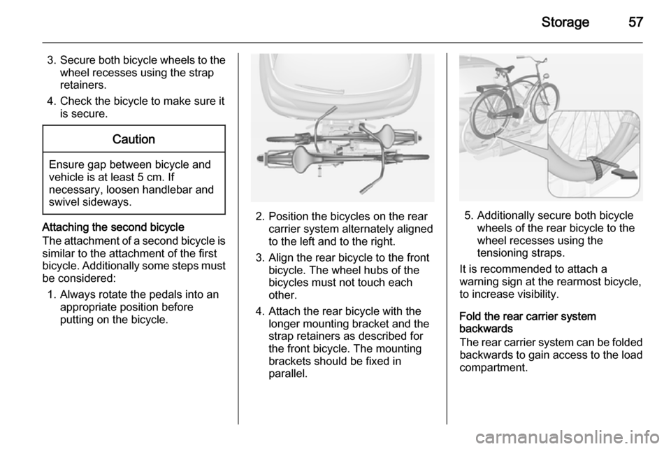
putting on the bicycle.2. Position the bicycles on the rear carrier system alternately aligned
to the left and to the right.
3. Align the rear bicycle to the front bicycle. The wheel hubs of the
bicycles must not touch each
other.
4. Attach the rear bicycle with the longer mounting bracket and the
strap retainers as described for
the front bicycle. The mounting
brackets should be fixed in
parallel.5. Additionally secure both bicycle wheels of the rear bicycle to the
wheel recesses using the
tensioning straps.
It is recommended to attach a
warning sign at the rearmost bicycle,
to increase visibility.
Fold the rear carrier system
backwards
The rear carrier system can be folded
backwards to gain access to the load
compartment.
Page 60 of 217

58Storage
■ Without attached adapter:
Push the lever (1) to disengage andhold.
Pull the rack (2) backwards to fold
the rear carrier system.
■ With attached adapter:
9 Warning
Take care when disengaging the
rear carrier system as it will tilt
backwards. Risk of injury.
Hold frame (1) of rear bicycle with
one hand and pull the loop (2) to
disengage.
Hold rear bicycle with both hands
and fold the rear carrier system
backwards.
To increase visibility, the tail lights of
the vehicle are activated when the
rear carrier system is folded back.
9 Warning
When folding the rear carrier
system forwards again, take care
that the system is engaged
securely.
Removing bicycles
Undo strap retainers on both bicycle
tyres.
Turn knob anti-clockwise and remove
mounting brackets.
Detaching adapter 1. Fold in wheel recesses.
2. Unbutton the strap.
Page 64 of 217
62Storage
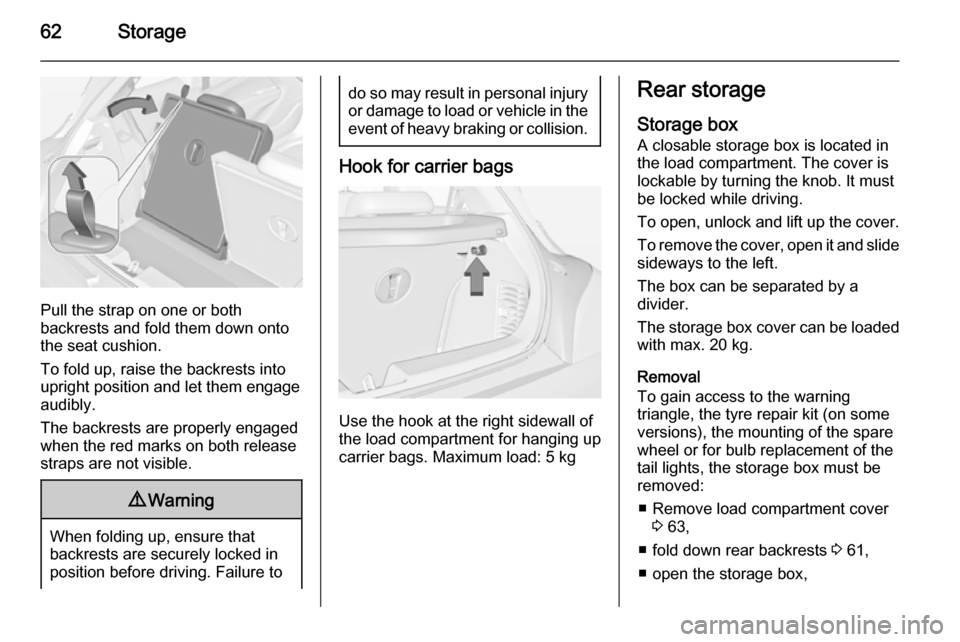
Pull the strap on one or both
backrests and fold them down onto the seat cushion.
To fold up, raise the backrests into
upright position and let them engage
audibly.
The backrests are properly engaged
when the red marks on both release
straps are not visible.
9 Warning
When folding up, ensure that
backrests are securely locked in
position before driving. Failure to
do so may result in personal injury or damage to load or vehicle in the event of heavy braking or collision.
Hook for carrier bags
Use the hook at the right sidewall of
the load compartment for hanging up carrier bags. Maximum load: 5 kg
Rear storage
Storage box A closable storage box is located in
the load compartment. The cover is lockable by turning the knob. It must
be locked while driving.
To open, unlock and lift up the cover.
To remove the cover, open it and slide
sideways to the left.
The box can be separated by a
divider.
The storage box cover can be loaded with max. 20 kg.
Removal
To gain access to the warning
triangle, the tyre repair kit (on some
versions), the mounting of the spare
wheel or for bulb replacement of the
tail lights, the storage box must be
removed:
■ Remove load compartment cover 3 63,
■ fold down rear backrests 3 61,
■ open the storage box,
Page 67 of 217

Storage65
■move floor cover slowly to the front,
taking care that the guiding bolts
slide into the attachments of the
load compartment, and allow the
floor cover to lower into position,
■ close the floor cover by folding the upper part to the rear, and fix it withthe Velcro fastener,
■ fold up rear backrests.
General hint9 Warning
For safety reasons, stow all parts
in the load compartment in its
position, always drive with a
closed rear floor cover and, if
possible, with folded up rear
backrests.
Otherwise, vehicle occupants
could be injured by objects being
thrown around in the event of
sharp braking, a sudden change in direction or an accident.
Lashing eyes
The lashing eyes are designed to
secure items against slippage, e.g.
using lashing straps or luggage net.
Page 69 of 217
Storage67Roof rack system
Roof rack For safety reasons and to avoiddamage to the roof, the vehicle
approved roof rack system is
recommended. For further
information contact your workshop.
Follow the installation instructions and remove the roof rack when not in
use.
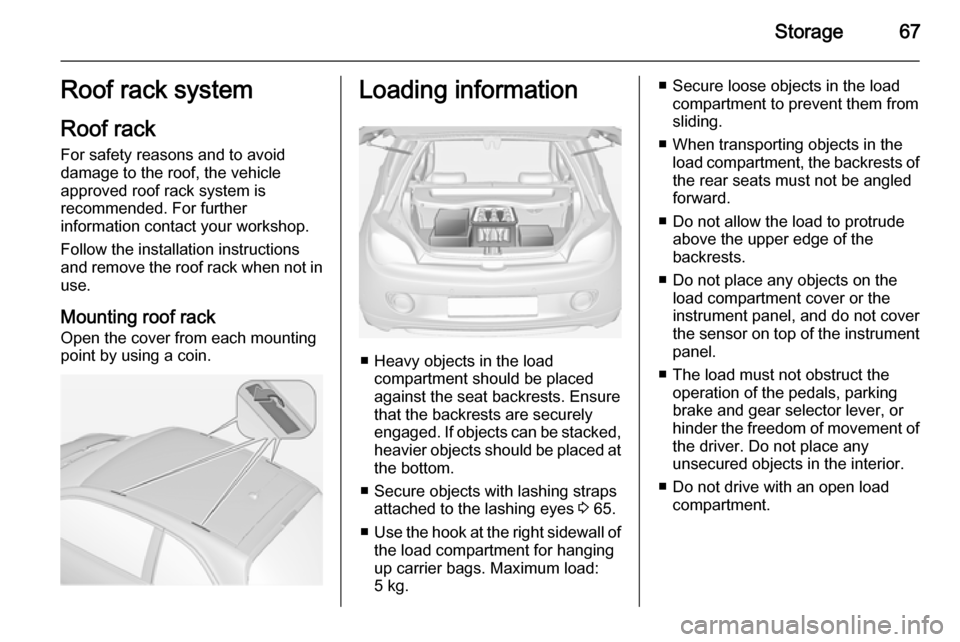
Mounting roof rack Open the cover from each mounting
point by using a coin.Loading information
■ Heavy objects in the load compartment should be placedagainst the seat backrests. Ensure
that the backrests are securely
engaged. If objects can be stacked, heavier objects should be placed at
the bottom.
■ Secure objects with lashing straps attached to the lashing eyes 3 65.
■ Use the hook at the right sidewall of
the load compartment for hanging
up carrier bags. Maximum load: 5 kg.
■ Secure loose objects in the load compartment to prevent them from
sliding.
■ When transporting objects in the load compartment, the backrests ofthe rear seats must not be angled
forward.
■ Do not allow the load to protrude above the upper edge of the
backrests.
■ Do not place any objects on the load compartment cover or theinstrument panel, and do not cover
the sensor on top of the instrument
panel.
■ The load must not obstruct the operation of the pedals, parking
brake and gear selector lever, or
hinder the freedom of movement of the driver. Do not place any
unsecured objects in the interior.
■ Do not drive with an open load compartment.
Page 70 of 217

68Storage9Warning
Always make sure that the load in
the vehicle is securely stowed.
Otherwise objects can be thrown
around inside the vehicle and
cause personal injury or damage
to the load or car.
■ The payload is the difference between the permitted gross
vehicle weight (see identification
plate 3 197) and the EC kerb
weight.
To calculate the payload, enter the
data for your vehicle in the Weights
table at the front of this manual.
The EC kerb weight includes
weights for the driver (68 kg),
luggage (7 kg) and all fluids (tank
90 % full).
Optional equipment and
accessories increase the kerb
weight.
■ Driving with a roof load increases the sensitivity of the vehicle to
cross-winds and has a detrimental
effect on vehicle handling due to
the vehicle's higher centre of
gravity. Distribute the load evenly
and secure it properly with retaining
straps. Adjust the tyre pressure and vehicle speed according to the load
conditions. Check and retighten the straps frequently.
Do not drive faster than 75 mph.
The permissible roof load is 50 kg. The roof load is the combined
weight of the roof rack and the load.
Page 97 of 217

Instruments and controls95
■ Lighting, bulb replacement
■ Wiper/washer system
■ Doors, windows
■ Radio remote control
■ Seat belts
■ Airbag systems
■ Engine and transmission
■ Tyre pressure
■ Vehicle battery
Vehicle messages on the
Colour-Info-Display Some important messages appear
additionally in the
Colour-Info-Display. Some
messages only pop up for a few
seconds.
Warning chimes When starting the engine or
whilst driving
Only one warning chime will sound at a time.The warning chime regarding
unfastened seat belts has priority
over any other warning chime.
■ If seat belt is not fastened.
■ If a door or the tailgate is not fully closed when starting off.
■ If a certain speed is exceeded with parking brake applied.
■ If a programmed speed is exceeded.
■ If a warning message or a warning code appears in the Driver
Information Centre or Graphic-Info- Display.
■ If the parking assist or advanced parking assist detects an object.
■ If the reverse gear is engaged and the rear end carrier extended.
When the vehicle is parked and/ or the driver's door is opened ■ When the key is in the ignition switch.
■ With exterior lights on.During an Autostop ■ If the driver's door is opened.
Battery voltage When the vehicle battery voltage is
running low, a warning message or
warning code 174 will appear in the
Driver Information Centre.
1. Switch off immediately electrical consumers which are not requiredfor a safe ride, such as seat
heating, heated rear window or
other main consumers.
2. Charge the vehicle battery by driving continuously for a while or
by using a charging device.
The warning message or warning
code will disappear after the engine has been started two times
consecutively without voltage drop.
If the vehicle battery cannot be
recharged, have the cause of the fault remedied by a workshop.
Page 154 of 217
152Vehicle care9Danger
The ignition system uses
extremely high voltage. Do not
touch.
Bonnet
Opening
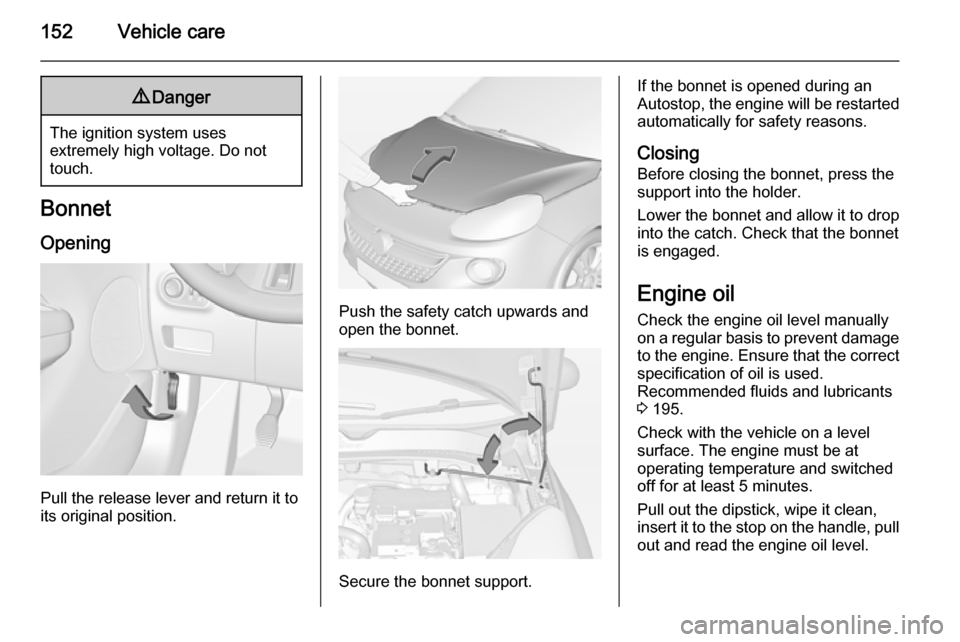
Pull the release lever and return it to
its original position.
Push the safety catch upwards and open the bonnet.
Secure the bonnet support.
If the bonnet is opened during an
Autostop, the engine will be restarted automatically for safety reasons.
Closing Before closing the bonnet, press the
support into the holder.
Lower the bonnet and allow it to drop
into the catch. Check that the bonnet
is engaged.
Engine oil
Check the engine oil level manually
on a regular basis to prevent damage
to the engine. Ensure that the correct specification of oil is used.
Recommended fluids and lubricants
3 195.
Check with the vehicle on a level
surface. The engine must be at
operating temperature and switched
off for at least 5 minutes.
Pull out the dipstick, wipe it clean, insert it to the stop on the handle, pull
out and read the engine oil level.
Page 163 of 217
Vehicle care161
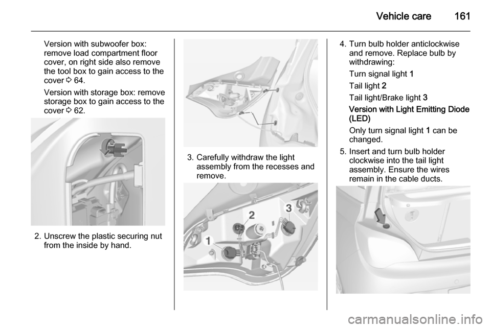
Version with subwoofer box:remove load compartment floor
cover, on right side also remove
the tool box to gain access to the
cover 3 64.
Version with storage box: remove
storage box to gain access to the
cover 3 62.
2. Unscrew the plastic securing nut
from the inside by hand.
3. Carefully withdraw the lightassembly from the recesses and
remove.
4. Turn bulb holder anticlockwise and remove. Replace bulb by
withdrawing:
Turn signal light 1
Tail light 2
Tail light/Brake light 3
Version with Light Emitting Diode (LED)
Only turn signal light 1 can be
changed.
5. Insert and turn bulb holder clockwise into the tail light
assembly. Ensure the wires
remain in the cable ducts.
Page 164 of 217
162Vehicle care
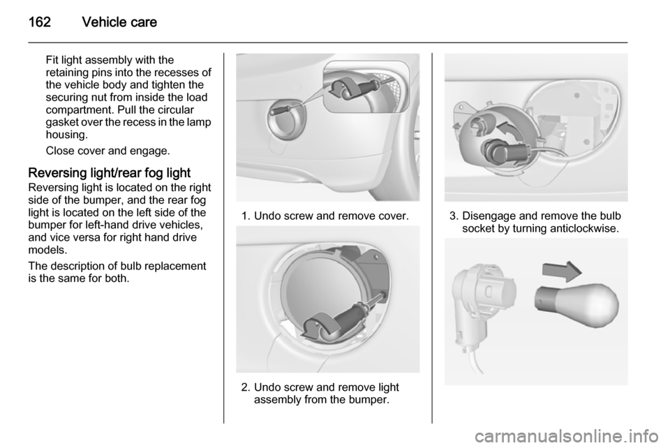
Fit light assembly with the
retaining pins into the recesses of
the vehicle body and tighten the
securing nut from inside the load
compartment. Pull the circular
gasket over the recess in the lamp housing.
Close cover and engage.
Reversing light/rear fog light
Reversing light is located on the right
side of the bumper, and the rear fog
light is located on the left side of the
bumper for left-hand drive vehicles,
and vice versa for right hand drive
models.
The description of bulb replacement
is the same for both.
1. Undo screw and remove cover.
2. Undo screw and remove light assembly from the bumper.
3. Disengage and remove the bulbsocket by turning anticlockwise.